3M 3MDW101 User manual

Installation and Operating Instructions For
3MDW101 Drinking Water System
Homeowner: Please retain for operation and future maintenance instructions.

SAFETY INFORMATION
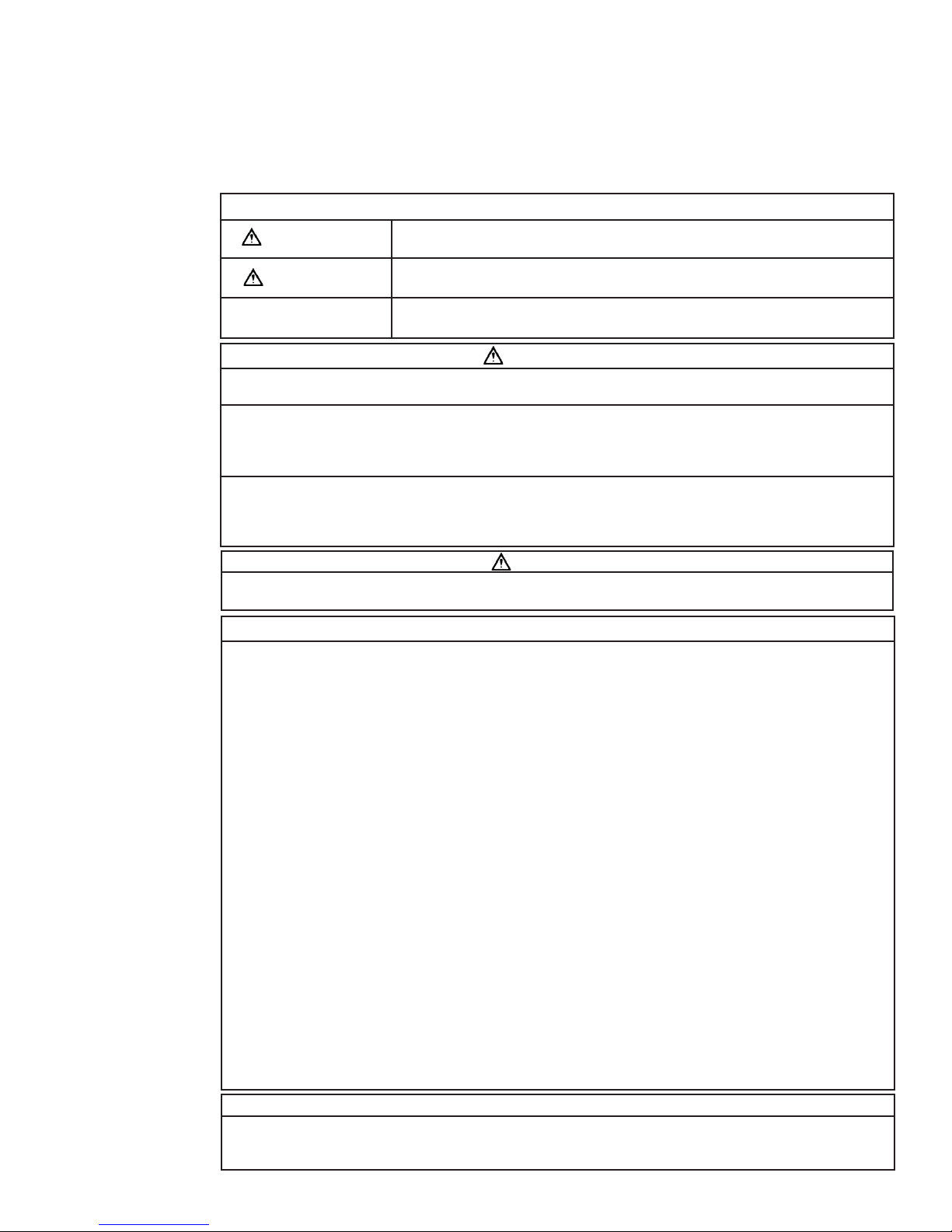
EXPLANATION OF SIGNAL WORD CONSEQUENCES
WARNING
WARNING
CAUTION
CAUTION
CAUTION
IMPORTANT NOTES
Read, understand, and follow all safety information contained in these instructions prior to installation and
use of the 3MDW101 Drinking Water System. Retain these instructions for future reference.
Intended use:
The 3MDW101 Drinking Water System is intended for use in filtering potable water in homes and has not been
evaluated for other uses. The system is installed at the point of use and typically installed under a sink. System
must be installed as specified in the installation instructions by a qualified professional.
Indicates a potentially hazardous situation, which, if not avoided, could result in
death or serious injury and/or property damage.
Indicates a potentially hazardous situation, which, if not avoided, may result in minor
or moderate injury and/or property damage.
Indicates a potentially hazardous situation, which, if not avoided, may result in
property damage.
To reduce the risk associated with choking:
• Do not allow children under 3 years of age to have access to small parts during the installation of this product.
To reduce the risk associated with ingestion of contaminants:
• Do not use with water that is microbiologically unsafe or of unknown quality without adequate disinfection before or
after the system. Systems certified for cyst reduction may be used on disinfected water that may contain filterable
cysts. EPA Establishment #070595-CT-001.
To reduce the risk associated with a hazardous voltage due to an installer drilling through existing electric
wiring or water pipes in the area of installation:
• Do not install near electric wiring or piping which may be in the path of a drilling tool when selecting the position to
mount the filter bracket.
To reduce the risk associated with property damage due to water leakage:
• Read and follow Use Instructions before installation and use of this system.
• Installation and use MUST comply with all state and local plumbing codes.
• Protect filter from freezing, remove replacement filter when temperatures are expected to drop below 40°F (4.4°C).
• Do not install systems in areas where ambient temperatures may go above 110°F (43.3°C).
• Do not install on hot water supply lines. The maximum operating water temperature of this filter system is
100°F (37.8°C).
• Do not install if water pressure exceeds 120 psi (827 kPa). If your water pressure exceeds 80 psi (552 kPa), you
must install a pressure limiting valve. Contact a plumbing professional if you are uncertain how to check your
water pressure.
• Do not install where water hammer conditions may occur. If water hammer conditions exist you must install a water
hammer arrester. Contact a plumbing professional if you are uncertain how to check for this condition.
• Where a backflow prevention device is installed on a water system, a device for controlling pressure due to thermal
expansion must be installed.
• Do not use a torch or other high temperature sources near filter system, cartridges, plastic fittings or
plastic plumbing.
• On plastic fittings, never use pipe sealant or pipe dope. Use PTFE thread tape only, pipe dope properties may
deteriorate plastic.
• Do not install in direct sunlight or outdoors.
• Do not install near water pipes which will be in path of a drilling tool when selecting the position to mount the bracket;
• Mount filter in such a position as to prevent it from being struck by other items used in the area of installation
(waste baskets, etc.);
• Ensure that the location and fasteners will support the weight of the system when installed and full of water.
• Ensure all tubing and fittings are secure and free of leaks.
• Do not install unit if collet is missing. Contact 3M if collets are missing from any fittings.
• The disposable replacement filter MUST be replaced every 6 months, at the rated capacity or sooner if a notice-
able reduction in flow rate occurs.
• Failure to follow instructions will void warranty.
• Allow a minimum of 2.5” (6.4 cm) clear space under filter to facilitate filter change.
• Install with the inlet and outlet ports as labeled. Make sure not to reverse connections.
2
CAUTION
To reduce the risk of eye injury while drilling countertop for faucet installations:
• Safety glasses MUST be worn during the sink hole drilling operations.

Parts and Materials Included:
1. Filter Head Assembly
2. Replacement Filter
3. Tubing Attached Faucet
4. 1/4” Union Adapter
5. 36” of 1/4” Tubing
6. 1/4” Feedwater Adapter
7. 2 Phillips Mounting Screws (not shown)
Items Required (not included):
• Drill (Cordless recommended)
• Adjustable wrench
• Phillips head screwdriver
• Razor knife or tube cutter
• May require special drill bits if drilling
hole in sink for dedicated faucet
GETTING STARTED
FILTER REPLACEMENT
1
2
46
5
3
1
2
4
3
5
6
3
CAUTION
To reduce the risk associated with property damage due to water leakage:
•
The disposable replacement filter MUST be replaced every 6 months, at the rated capacity or sooner if a
noticeable reduction in flow rate occurs.
• Installation requires some household tools and novice plumbing skills. If you replace your own kitchen
and bathroom faucets, you can handle this!
• Installation may require drilling a hole in your sink top. A variable speed drill and specialized drill bits
may be needed. We highly recommend professional installation!

1. Open faucet and turn off cold water supply valve and
remove existing water supply tubing and/or fitting.
2. Select and mark a location for the system under the sink
that allows access for replacement filter changeout and
convenient hook up to the tubing attached faucet.
NOTE: 1/4” union adapter along with segment of 36” long
tubing can be used to extend tubing attached faucet.
3. Using Filter Head Assembly as a guide, fasten Filter Head
Assembly to wall with 2 Phillips mounting screws supplied.
Mark hole locations so that there is 1 1/2” between the
screws (see Figure 2), from center of each screw. When
installed, filter bottom should be at least 2 1/2” from sink
cabinet floor to facilitate filter change. Install screws, but
only halfway, so you can easily slip the bracket to wall
before firmly setting screws.
IMPORTANT: INSTALLATION INSTRUCTIONS
Figure 2
INLET
OUTLET
For Use With Cold Water Only.
NOTE: Remove items from under the sink. Place catch basin under cold water faucet stem to collect small amounts of
water that may run out when disconnecting water supply lines.
4
Drilling 9/16” diameter hole through countertop or stainless steel sink:
1. Locate area to be drilled. Mark center of hole with center punch.
2. Drill hole with 9/16” drill bit suitable for countertop materials or cast iron/stainless steel.
3. With grinding wheel or file,
smooth out any rough edges.
Installing the faucet:
1. Slide the following parts in the
order specified up blue tubing and
threaded stem:
a. Metal bezel
b. Large rubber washer
2. Next, feed blue tubing and faucet
stem down through faucet mount-
ing hole.
3. From underneath sink, assemble
the black spacer, star washer,
and hex nut (as shown) onto the
threaded stem and tighten by hand.
4. With a padded adjustable wrench,
turn the faucet base (above the
counter) to the right to securely
fasten. Raise faucet handle and
remove plastic shipping tube from
base.
5. Insert faucet neck onto base until
seated and align over sink. Lower
faucet handle.
DRINKING WATER FAUCET INSTALLATION
Metal Bezel
Rubber Washer
1
Metal Bezel
Rubber Washer
Countertop
2
Metal Bezel
Rubber Washer
Countertop
Plastic Backing Spacer
Star Washer
Hex Nut
3
Metal Bezel
Rubber Washer
Countertop
Plastic Backing Spacer
Star Washer
Hex Nut
4, 5
Installed
Shipping Tube
Shipping Tube
Shipping Tube
Figure 1
• The drinking water system faucet should be located on a flat surface, conveniently located near the sink, so that it
empties into the sink. Most sinks have pre-drilled holes designated for sprayers, soap dispensers, and other ac-
cessories. If your sink does not have an extra hole, we highly recommend professional installation.
• Porcelain, enamel, and ceramic sinks require special procedures for drilling holes. Professional installation is
highly recommended. (See page 6)
IMPORTANT NOTES
To reduce the risk of eye injury while drilling countertop for faucet installations:
• Safety glasses MUST be worn during the sink hole drilling operations.
CAUTION

5
6. Insert Blue Tubing from the 1/4” Feedwater Adapter into the filter INLET
fitting as shown in Figure 5. Refer to the “Using Push-In Fittings” section
for detailed instructions.
7. Insert tubing from faucet into the filter OUTLET fitting as shown in Figure
5. Refer to the “Using Push-In Fittings” section for detailed instructions.
8. Remove filter from box, and remove sanitary protective cap from replace-
ment filter. Ensure both o-rings are present on the new filter and are
seated into grooves; moisten o-rings with water. DO NOT use any petro-
leum products to lubricate the o-rings.
9. Align tabs of replacement filter with head assembly and insert replacement
filter into head assembly. Turn replacement filter to the right (clockwise)
until it stops (about 1/4 turn). The filter is now installed. (See Figure 5).
10. Turn water supply back on from the shutoff valve on cold water line. This
will pressurize the filter system and begin sending filtered water to the
faucet. Look for leaks. If leaks occur, see Troubleshooting Guide. Flush
the filter for four (4) gallons (approx. 5 minutes).
INSTALLATION INSTRUCTIONS (CONTINUED)
INLET OUTLET
Figure 5
To Release Tubing
Push in grey collet to release tubing. With collet
held, pull tubing straight out.
Collet
Backstop
“Using Push-In Fittings”
To Attach Tubing
Push tubing in as far as it will go. Tubing must be inserted past
o-ring and hit backstop. Pull tube to ensure it is secured.
CAUTION
To reduce the risk associated with property damage due to water leakage:
• Ensure all tubing and fittings are secure and free of leaks.
Figure 4
1/4” Blue
Tubing
1/2” IPS
Faucet Stem
1/2” IPS
Cold Water
Feed Tube
Feedwater
Adapter
4. Determine length of tubing required from filter head as-
sembly to faucet and from water supply line to filter head
assembly by holding tubing in place ensuring it is of ap-
propriate length. Do not kink tubing as this will impede
water flow. If necessary, loop tubing around to avoid it
being kinked.
Cut tubing straight with a utility knife. (See Figure 3).
5. Locate the cold water stem on the underside of the faucet
fixture. Place basin or towel under the cold water supply
valve. Unscrew the cold water feed tube from the faucet
stem. Locate the 1/4” Feedwater Adapter that came with
your Drinking Water System. Insert the black gasket into
the threaded adapter and tighten onto the 1/2” IPS Faucet
Stem undersink, making sure that 1/4” side connection is
accessible and not facing the wall. Make sure not to over
tighten.
Take the 1/2” IPS Cold Water Feed Tube and attach to the
Feedwater Adapter, making sure not to over tighten.
Locate the 1/4” Blue Tubing and insert into the 1/4” out-
let of Feedwater Adapter (Figure 4). See “Using Push-In
Fittings.”
Correct Incorrect
Figure 3

Drilling Hole through Porcelain/Enamel/Ceramic Sinks
Recommended Tools:
• Variable Speed Drill
• Porcelain Cutter Tool Set (9/16” Size)
• Plumber’s Putty
Note: It is important to understand this procedure.
1. The glassy layer of porcelain/enamel/ceramic must be scored through to the metal base, creating a disk.
2. This disk must be removed while protecting the surrounding decorative coating against chipping or fracturing.
3. The base metal must be drilled through to complete the hole.
Procedure:
1. Mark center for 9/16” hole.
2. Form a dam of shallow putty around hole location and fill with enough water to lubricate carbide drill bit.
3. Carefully drill pilot hole through porcelain/enamel/ceramic and base metal using a carbide pilot drill bit. Always oper-
ate drill with light pressure at slow speed (300 - 400 rpm).
4. Drill porcelain/enamel/ceramic using special 9/16” cutting tool, making certain a complete ring has been cut through
to the sink’s metal base.
5. Change to metal cutting drill bit and drill out the center of the ring, making sure not to contact other rim of decorative
coating. Cut through metal sink base.
1. Grasp installed filter and turn to the left (counterclockwise) until filter comes to a complete stop. Gently pull down-
ward to remove.
2. Remove replacement filter from box, and remove sanitary protective cap from replacement filter. Ensure both o-rings
are present on the new replacement filter and are seated into grooves; moisten o-rings with water. DO NOT use any
petroleum products to lubricate the o-rings.
3. Align tabs of new replacement filter with existing filter head and insert new replacement filter into head. Turn
filter to the right (clockwise) until filter stops.
4. Open the dedicated faucet and flush new replacement filter for four (4) gallons (approximately 5 minutes)
before use. It may sputter as it releases trapped air.
5. Close dedicated faucet. System is now under pressure and can be inspected for leaks. Repair any leaks as
needed before continuing. The system is now ready for use.
FILTER REPLACEMENT INSTRUCTIONS
DRILLING HOLE THROUGH
PORCELAIN/ENAMEL/CERAMIC SINKS
Water leaks at push-in connections:
Push tubing in as far as it will go. If leaking continues, shut off water at the cold water supply valve and remove water
line by pushing in on the connector collar while pulling the tubing away. Inspect tubing for cracks and scratches. If tub-
ing is cracked or scratched, simply cut that portion away and reinsert tubing into push-in fitting.
Make sure tubing is cut straight. If not, recut correctly. Refer to Figure 3.
If water leaks, please verify that the o-rings are properly seated in their grooves.
Water does not flow from the drinking water system faucet:
Check to see if the main water line valve is open, allowing water to flow to the filter.
Water appears cloudy or air comes out of the drinking water system faucet:
Flush the filter for four (4) gallons (approx. 5 minutes) to remove any trapped air.
TROUBLESHOOTING GUIDE
CAUTION
To reduce the risk associated with property damage due to water leakage:
• The disposable replacement filter must be replaced every 6 months, at the rated capacity or sooner if a no-
ticeable reduction in flow rate occurs.
IF YOU ARE READING THIS SECTION, PROFESSIONAL INSTALLATION IS HIGHLY RECOMMENDED.
6
To reduce the risk of eye injury while drilling countertop for faucet installations:
• Safety glasses MUST be worn during the sink hole drilling operations.
CAUTION

7
Limited Warranty: 3M Purification Inc. warrants this Product will be free from defects in material and manufacture for the fol-
lowing periods from the date of purchase. Twelve (12) year for the Product, except for the replacement filter cartridge, which is
warranted for one (1) year. This warranty does not cover failures resulting from abuse, misuse, alteration or damage not caused
by 3M Purification Inc. or failure to follow installation and use instructions. No warranty is given as to the service life of any filter
cartridge or membrane as it will vary with local water conditions and water consumption. 3M PURIFICATION INC. MAKES NO
OTHER WARRANTIES OR CONDITIONS, EXPRESS OR IMPLIED, INCLUDING, BUT NOT LIMITED TO, ANY IMPLIED WAR-
RANTY OR CONDITION OF MERCHANTABILITY OR FITNESS FOR A PARTICULAR PURPOSE OR ANY IMPLIED WARRANTY
OR CONDITION ARISING OUT OF A COURSE OF DEALING, CUSTOMER OR USAGE OF TRADE. If the Product fails to satisfy
this Limited Warranty during the warranty period, 3M Purification Inc. will replace the Product or refund your Product purchase
price. This warranty does not cover labor. The remedy stated in this paragraph is Customer’s sole remedy and 3M Purifica-
tion Inc.’s exclusive obligation.
This warranty gives you specific legal rights, and you may have other rights which may vary from state to state, or country to
country. For any warranty questions, please call 855-3M-WATER (855-369-2837) or mail your request to: Warranty Claims,
3M Purification Inc., 400 Research Parkway, Meriden, CT 06450. Proof of purchase (original sales receipt) must accompany the
warranty claim, along with a complete description of the Product, model number and alleged defect.
Limitation of Liability: 3M Purification Inc. will not be liable for any loss or damage arising from this 3M product, whether
direct, indirect, special, incidental, or consequential, regardless of the legal theory asserted, including warranty, contract,
negligence or strict liability. Some states and countries do not allow the exclusion or limitation of incidental or consequential
damages, so the above limitation or exclusion may not apply to you.
LIMITED WARRANTY

3M is a trademark of 3M Company.
© 2012 3M Company. All rights reserved.
INSTR8032 0512
3M Purification Inc.
400 Research Parkway
Meriden, CT 06450
855-3M-WATER (855-369-2837)
www.3MWater.com
Table of contents
Other 3M Water Filtration System manuals