ECS 865GV-M Deluxe User manual


ii
Copyright
This publication, including all photographs, illustrations and software, is protected under international copyright laws, with all rights reserved. Neither this
manual, nor any of the material contained herein, may be reproduced without written consent of the author.
Version 5.0
Disclaimer
The information in this document is subject to change without notice. The manufacturer makes no representations or warranties with respect to the
contents hereof and specifically disclaims any implied warranties of merchantability or fitness for any particular purpose. The manufacturer reserves the
right to revise this publication and to make changes from time to time in the content hereof without obligation of the manufacturer to notify any person
of such revision or changes.
Trademark Recognition
Microsoft, MS-DOS and Windows are registered trademarks of Microsoft Corp.
MMX, Pentium, Pentium-II, Pentium-III, Celeron are registered trademarks of Intel Corporation.
Other product names used in this manual are the properties of their respective owners and are acknowledged.
Federal Communications Commission (FCC)
This equipment has been tested and found to comply with the limits for a Class B digital device, pursuant to Part 15 of the FCC Rules. These limits are
designed to provide reasonable protection against harmful interference in a residential installation. This equipment generates, uses, and can radiate radio
frequency energy and, if not installed and used in accordance with the instructions, may cause harmful interference to radio communications. However,
there is no guarantee that interference will not occur in a particular installation. If this equipment does cause harmful interference to radio or television
reception, which can be determined by turning the equipment off and on, the user is encouraged to try to correct the interference by one or more of the
following measures:
• Reorient or relocate the receiving antenna.
• Increase the separation between the equipment and the receiver.
• Connect the equipment onto an outlet on a circuit different from that to which the receiver is connected.
• Consult the dealer or an experienced radio/TV technician for help.
Preface

iiii
Shielded interconnect cables and a shielded AC power cable must be employed with this equipment to ensure compliance with the pertinent RF emission
limits governing this device. Changes or modifications not expressly approved by the system’s manufacturer could void the user’s authority to operate the
equipment.
Declaration of Conformity
This device complies with part 15 of the FCC rules. Operation is subject to the following conditions:
This device may not cause harmful interference, and
This device must accept any interference received, including interference that may cause undesired operation.
Canadian Department of Communications
• This class B digital apparatus meets all requirements of the Canadian Interference-causing Equipment Regulations.
• Cet appareil numérique de la classe B respecte toutes les exigences du Réglement sur le matériel brouilieur du Canada.
About the Manual
Chapter 1
Introducing the Motherboard
Chapter 2
Installing the Motherboard
Chapter 3
Using BIOS
Chapter 4
Using the Motherboard Software
Describes features of the motherboard.
The manual consists the following:
Go to page 1
Go to page 35
Describes installation of motherboard components.
Provides information on using the BIOS Setup Utility.
Describes the motherboard software
Go to page 5
Go to page 17

TT
TT
TABLE OF CONTENTSABLE OF CONTENTS
ABLE OF CONTENTSABLE OF CONTENTS
ABLE OF CONTENTS
Preface i
Chapter 1
1
IntroducingtheMotherboard 1
Introduction..........................................................................................................................................................................................................1
Feature..................................................................................................................................................................................................................2
MotherboardComponents.................................................................................................................................................................................4
Chapter2 5
InstallingtheMotherboard 5
SafetyPrecautions.................................................................................................................................................................................................5
ChoosingaComputer Case.................................................................................................................................................................................5
InstallingtheMotherboard ina Case.................................................................................................................................................................5
CheckingJumperSettings...................................................................................................................................................................................6
Setting Jumpers..................................................................................................................................................................................................6
Checking Jumper Settings..................................................................................................................................................................................6
Jumper Settings..................................................................................................................................................................................................7
ConnectingCaseComponents...........................................................................................................................................................................7
Front Panel Header............................................................................................................................................................................................8
InstallingHardware..............................................................................................................................................................................................9
Installing the processor......................................................................................................................................................................................9
Installing Memory Modules..............................................................................................................................................................................10
Installing a Hard Disk Drive/CD-ROM/SATA Hard Drive.............................................................................................................................11
Installing a Floppy Diskette Drive....................................................................................................................................................................12
iii

Installing Add-on Cards...................................................................................................................................................................................13
Connecting Optional Devices............................................................................................................................................................................14
ConnectingI/ODevices....................................................................................................................................................................................16
Chapter 3 17
UsingBIOS 17
AbouttheSetup Utility.......................................................................................................................................................................................17
The Standard Configuration................................................................................................................................................................................17
Entering the Setup Utility..................................................................................................................................................................................17
Updating the BIOS...............................................................................................................................................................................................18
UsingBIOS.............................................................................................................................................................................................................19
Standard CMOS Features.....................................................................................................................................................................................19
Advanced BIOS Features.....................................................................................................................................................................................20
AdvancedChipset Features......................................................................................................................................................................................23
Integrated Peripherals...........................................................................................................................................................................................24
Power Management Setup.....................................................................................................................................................................................28
PNP/PCI Configurations.......................................................................................................................................................................................30
PCHealth Status.....................................................................................................................................................................................................31
Frequency Control............................................................................................................................................................................................32
Load Fail-Safe Defaults.........................................................................................................................................................................................33
Load Optimized Defaults.....................................................................................................................................................................................33
Set Password..........................................................................................................................................................................................................33
Save& Exit Setup...................................................................................................................................................................................................34
Exit Without Saving.............................................................................................................................................................................................34
.
iv

Chapter 4 35
UsingtheMotherboardSoftware 35
AbouttheSoftware CD-ROM...........................................................................................................................................................................35
Auto-installingunderWindows98/ME/2000/XP...............................................................................................................................................35
Running Setup........................................................................................................................................................................................................36
ManualInstallation....................................................................................................................................................................................37
UtilitySoftwareReference................................................................................................................................................................................37
Multi-LanguageTranslation
v

Chapter1
IntroducingtheMotherboard
1
IntroducingtheMotherboard
Introduction
Thank you for choosing 865GV-M Deluxe motherboard of great perfor-
mance and with enhanced function. 865GV-M Deluxe motherboard carries
a micro-ATX form factor of 244 x 244 mm. It supports Socket 478 Pentium
4/Prescott processors with system bus speeds up to 800/533/400MHz and
“Hyper-Threading” technology for high-end business or personal desktop
markets.
It incorporates chipset of Intel 865GV Northbridge and ICH5 82801EB
Southbridge.
The 865GV (GMCH) Northbridge is designed for use in a desktop system
based on a Pentium 4 processor with 512-KB L2 cache on 0.13 micron
process and the processor code named Prescott. It supports up to two 64-bit
wide DDR data channels and 128-Mb, 256-Mb. 512-Mb technology with
page size from 4KB to 64KB.
The ICH5 Southbridge integrates an Ultra ATA 100 controller, two Serial
ATA host controllers, one EHCI host controller and four UHCI host con-
trollers supporting eight external USB 2.0 ports, LPC interface controller,
flash BIOS interface controller, PCI interface controller, AC’97 digital con-
troller, integrated LAN controller. The southbridge also provide IDE con-
troller which supports Ultra ATA100/66/33.
There is an advanced full set of I/O ports in the rear panel, including PS/2
mouse and keyboard connectors, COM1, LPT1, VGA port, and four USB
ports, one optional LAN port, and audio jacks for microphone, line-in, and
line-out.
In addition to its excellent performance and stability, the motherboard is
highly suited for Internet and rich multimedia applications, including streaming
video download and are ideal for workstations and high-end home use.

2
IntroducingtheMotherboard
Feature
865GV-M Deluxe uses a mPGA 478-pin socket that carries the following
features:
• Accommodates Intel Pentium4/Prescott CPU with Hyper-
Threading Technology
• Supports a system bus (FSB) of 800/533/400 MHz
“Hyper-Threading” technology enables the operating system into think-
ing it’s hooked up to two processors, allowing two threads to be run in
parallel, both on separate “logical” processors within the same physical
processor.
Processor
AC’97 Audio CODEC
The AC’97 Audio CODEC is compliant with the AC’97 2.3 specifica-
tion that meets the PC2001 requirements and supports SPDIF out. It
also has a built-in buffer and internal PLL. Features include support for
analog switch for rear-out (share), the line-in jack (share), center/bass
(share), and MIC jack to output 6 channels audio.
This motherboard can accommodate 2.5V DDR SDRAM, supporting
dual-channel(128 bits wide) DDR memory and single-channel (64 bits
wide) DDR memory. It accommodates four unbuffered 2.5V 184-pin
slots with a total maximum capacity of 4 GB.
Memory
ICH5 (SB) •Integrated IDE Controller supporting Ultra ATA/
100/66/33, BMIDE and PIO modes
•Compliant with PCI 2.3 specificaiton at 33 MHz
•Integrated Serial ATA Host Controllers,
supporting data transfer rates up to 1.5Gb/s
•Compliant with AC’97 v2.3 supporting for up to
six channels of PCM audio output and wake-up
events
•Includes 4 UHCI USB 2.0 Host Controllers,
increasing the number of external ports to
eight
Intel’s 865GV Northbridge (NB) and ICH5 Southbridge (SB) chipsets are
based on an innovative and scalable architecture with proven reliability
and performance.
Chipset
865GV(NB) •Supports a single processor with a data
transfer-rate of 800/533/400MHz
•Supports DDR-SDRAM at 400/333/266MHz
Operation
•Communication Streaming Architecture
Interface, supporting 8-bit Hub Interface 1.5
electrical/transfer protocol
•Hub Interface, supporting 266 MB/s point-to-
point connection to the ICH5

3
IntroducingtheMotherboard
Graphics
• Embedded Intel Extreme Graphics II
• 3D setup and render engine
• 2D/3D graphics enhancement
• Video DVD/PV-VCR
• High quality texture engine
The motherboard has a full set of I/O ports and connectors:
• Two PS/2 ports for mouse and keyboard
• One serial port
• One parallel port
• Four USB ports
• One LAN port (optional)
• One VGA port
• Audio jacks for microphone, line-in and line-out
Integrated I/O
This motherboard uses Award BIOS that enables users to configure
many system features including the following:
• Power management
• Wake-up alarms
• CPU parameters
• CPU and memroy timing
The firmware can also be used to set parameters for different processor
clock speeds.
BIOS Firmware
Some hardware specifications and software items are subject
to change with out prior notice.
EnglishEnglish
EnglishEnglish
English
The motherboard comes with the following expansion options:
• Three 32-bit PCI slots
• Two IDE connectors which support four IDE devices
• One floppy disk drive interface
• Two 7-pin SATA connectors
The motherboard supports Ultra DMA bus mastering with transfer rates
of 33/66/100 MB/s.
The single-chip device is a highly integrated, cost-effective Fast Ethernet
controller that provides 32-bit performance, PCI bus master capability,
and full compliance with IEEE 802.3u 100Base-T specifications and
IEEE 802.3x Full Duplex Flow Control. It can support 10 Mb/s and
100Mb/s N-way auto-negotiation operation and Wake-On-LAN (WOL)
function and remote wake-up.
Expansion Options
Onboard LAN (Optional)
4
IntroducingtheMotherboard
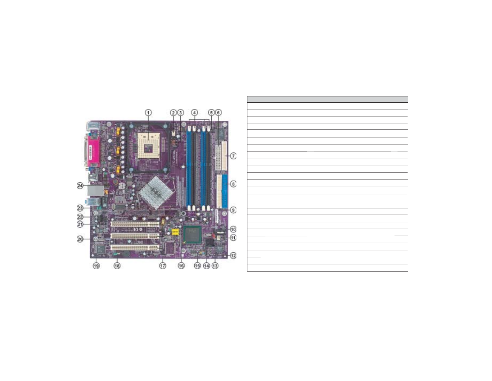
MotherboardComponents Table of Motherboard Components
This concludes Chapter 1. The next chapter explains how to install the
motherboard.
1 CPU Socket mPGA478 socket for Pentium 4 CPUs
3 CPUFAN1 CPU cooling fan connector
4 DIMM1~DIMM4 184-pin DDR SDRAM slots
5 IR1 Infrared header
6 ATX1 Standard 20-pin ATX power connector
7 FDD1 Floppy disk drive connector
8 IDE1 Primary IDE connector
9 IDE2 Secondary IDE connector
10 JP1 Clear CMOS jumper
11 SYSFAN1 System fan connector
12 JP3 BIOS flash protect jumper
13 SATA1~SATA2 Serial ATA connectors
14 SJ1 Single-color LED header
15 PANEL1 Panel connector for case switches and LEDs
16 USB3~USB4 Front Panel USB header
2 PWRFAN1 Power fan connector
LABEL COMPONENT
17 PCI1~PCI3 32-bit PCI slots
18 SPK1 Speaker header
19 JP4 LAN function Enable/Disable jumper
20 SPDIFO1 SPDIF out header
21 AUXIN1 Auxiliary in header
22 CDIN1 CD-in connector
23 AUDIO1 Front panel MIC/Speaker Out header
24 ATX12V 4-pin +12V power connector

5
Chapter2
InstallingtheMotherboard
InstallingtheMotherboard
SafetyPrecautions
•Follow these safety precautions when installing the
motherboard
•Wear a grounding strap attached to a grounded device to avoid
damage from static electricity
•Discharge static electricity by touching the metal case of a
safely grounded object before working on the motherboard
•Leave components in the static-proof bags they came in
•Hold all circuit boards by the edges. Do not bend circuit boards
ChoosingaComputerCase
There are many types of computer cases on the market. The motherboard
complies with the specifications for the micro-ATX system case. First,
some features on the motherboard are implemented by cabling connectors
on the motherboard to indicators and switches on the system case. Make
sure that your case supports all the features required. Secondly, 865GV-M
Deluxe supports one or two floppy diskette drives and four enhanced IDE
drives. Make sure that your case has sufficient power and space for all drives
that you intend to install.
Most cases have a choice of I/O templates in the rear panel. Make sure that
the I/O template in the case matches the I/O ports installed on the rear edge
of the motherboard.
This motherboard carries a micro-ATX form factor of 244 x 244 mm.
Choose a case that accommodates this form factor.
InstallingtheMotherboardina Case
Refer to the following illustration and instructions for installing the
motherboard in a case:
This illustration shows an example of a motherboard being installed in a
tower-type case:
Do not over-tighten the screws as this can stress the
motherboard.
Most system cases have mounting brackets installed in the case, which
correspond the holes in the motherboard. Place the motherboard over the
mounting brackets and secure the motherboard onto the mounting brackets
with screws.
Ensure that your case has an I/O template that supports the I/O ports and
expansion slots on your motherboard.

6
InstallingtheMotherboard
CheckingJumperSettings
This section explains how to set jumpers for correct configuration of the
motherboard.
Setting Jumpers
Use the motherboard jumpers to set system configuration options. Jumpers
with more than one pin are numbered. When setting the jumpers, ensure
that the jumper caps are placed on the correct pins.
The illustrations show a 2-pin
jumper. When the jumper cap is
placed on both pins, the jumper
is SHORT. If you remove the
jumper cap, or place the jumper
cap on just one pin, the jumper is
OPEN.
SHORT OPEN
This illustration shows a 3-pin
jumper. Pins 1 and 2 are SHORT
Checking Jumper Settings
The following illustration shows the location of the motherboard jumpers.
Pin 1 is labeled.

7
InstallingtheMotherboard
Jumper Settings
Jumper Description Setting (default)
JP1 3-pin CLEAR CMOS 1-2: Normal
2-3: Clear
OPEN: Disable
SHORT: Enable
ConnectingaCaseComponents
After you have installed the motherboard into a case, you can begin con-
necting the motherboard components. Refer to the following:
1. Connect the CPU cooling fan cable to CPUFAN1.
2. Connect the Northbridge cooling fan connector to PWRFAN1.
3. Connect the case cooling fan connector to SYSFAN1.
4. Connect the case speaker cable to SPK1.
5. Connect the case switches and indicator LEDs to the PANEL1.
If there are three pins in the case LED cable, connect to SJ1.
6. Connect the standard power supply connector to ATX1.
7. Connect the auxiliary case power supply connector to ATX12V.
Before clearing the CMOS,
make sure to turn the sys-
tem off.
JP4 3-pin LAN Function 1-2: Enable
2-3: Disable
JP3 2-pin BIOS Write
Protect
CPUFAN1/PWRFAN1/SYSFAN1:FAN PowerConnectors
Pin Signal Name Function
1GND System Ground
2+12V Power +12V
3Sense Sensor
8
InstallingtheMotherboard
ATX12V:ATX 12V Power Connector
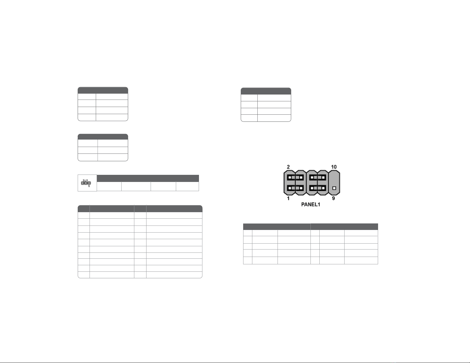
Front Panel Header
The front panel header (PANEL1) provides a standard set of switch and
LED headers commonly found on ATX or micro-ATX cases. Refer to the
table below for information:
Pin Signal Name
4+12V
3+12V
2Ground
1Ground
ATX1:ATX 20-pin Power Connector
SPK1: Internal speaker
Pin Signal Name
1Signal
2Buzzer
3Key
4VCC
SJ1: Single-color LED header
ACPI LED function
1+3.3V 11 +3.3V
2+3.3V 12 -12V
Pin Signal Name Pin Signal Name
10 +12V 20 +5V
3Ground 13 Ground
4+5V 14 PS ON#
5Ground 15 Ground
6+5V 16 Ground
7Ground 17 Ground
8PWRGD 18 -5V
9+5VSB 19 +5V
Pin Signal Name
1ACPI LED
2ACPI LED
35VSB
Pin Signal Name
Light Blinking Blinking Dark
S0 S1 S3 S4/S5
Pin Signal Function Pin Signal Function
1 HD_LED_P Hard disk LED+ 2 FP PWR/SLP *MSG LED+
3 HD_LED_N Hard disk LED-
5 RST_SW_N Reset Switch (-)
7 RST_SW_P Reset Switch (+)
9 RSVD Reserved
4 FP PWR/SLP *MSG LED-
6 PWR_SW_P Power Switch (+)
8 PWR_SW_N Power Switch (-)
10 Key No pin
* MSG LED (dual color or single color)

9
InstallingtheMotherboard
Hard Drive Activity LED
Connecting pins 1 and 3 to a front panel mounted LED provides visual
indication that data is being read from or written to the hard drive. For the
LED to function properly, an IDE drive should be connected to the onboard
IDE interface. The LED will also show activity for devices connected to the
SCSI (hard drive activity LED) connector.
Power/Sleep/Message waiting LED
Connecting pins 2 and 4 to a single or dual-color, front panel mounted LED
provides power on/off, sleep, and message waiting indication.
Reset Switch
Supporting the reset function requires connecting pin 5 and 7 to a momen-
tary-contact switch that is normally open. When the switch is closed, the
board resets and runs POST.
Power Switch
Supporting the power on/off function requires connecting pins 6 and 8 to a
momentary-contact switch that is normally open. The switch should main-
tain contact for at least 50 ms to signal the power supply to switch on or off.
The time requirement is due to internal de-bounce circuitry. After receiving
a power on/off signal, at least two seconds elapses before the power supply
recognizes another on/off signal.
InstallingHardware
Installing the Processor
Caution: When installing a CPU heatsink and cooling fan
make sure that you DO NOT scratch the motherboard or any
of the surface-mount resistors with the clip of the cooling fan.
If the clip of the cooling fan scrapes across the motherboard,
you may cause serious damage to the motherboard or its
components.
On most motherboards, there are small surface-mount
resistors near the processor socket, which may be damaged if
the cooling fan is carelessly installed.
Avoid using cooling fans with sharp edges on the fan casing
and the clips. Also, install the cooling fan in a well-lit work
area so that you can clearly see the motherboard and
processor socket.
Before installing the Processor
This motherboard automatically determines the CPU clock frequency and
system bus frequency for the processor. You may be able to change these
settings by making changes to jumpers on the motherboard, or changing the
settings in the system Setup Utility. We strongly recommend that you do
not over-clock processors or other components to run faster than their
rated speed.
Warning: Over-clocking components can adversely affect the
reliability of the system and introduce errors into your system.
Over-clocking can permanently damage the motherboard by
generating excess heat in components that are run beyond the
rated limits.

10
InstallingtheMotherboard
Installing Memory Modules
865GV-M Deluxe accommodates four 184-pin 2.5V unbuffered Double Data
Rate (DDR) SDRAM (Synchronous Dynamic Random Access Memory)
memory modules, supporting Dual-channel DDR memory(128-bit wide).
865GV-M Deluxe can support DDR400/DDR333/DDR266 memory mod-
ules . DDR400 can provide a total bandwidth of 3.2GB/s, DDR333 can
provide a total bandwidth of 2.7GB/s and DDR266 can provide a total
bandwidth of 2.1GB/S. The total maximum memory size is 4 GB.
DDR SDRAM memory module table
This motherboard has a Socket 478 processor socket. When choosing a
processor, consider the performance requirements of the system. Perfor-
mance is based on the processor design, the clock speed and system bus
frequency of the processor, and the quantity of internal cache memory and
external cache memory.
1. Install your CPU. Pull up the lever away
from the socket and lift up to 90-degree
angle.
2. Locate the CPU cut edge (the corner with the
pin hold noticeably missing). Align and insert
the CPU correctly.
3. Press the lever down and apply thermal
grease on top of the CPU.
4. Put the CPU Fan down on the retention
module and snap the four retention legs of
the cooling fan into place.
5. Flip the levers over to lock the heat sink in
place and connect the CPU cooling Fan
power cable to the CPUFAN connector. This
completes the installation.
To achieve better airflow rates and heat dissipation, we suggest
that you use a high quality fan with 4800 rpm at least. CPU fan
and heatsink installation procedures may vary with the type of
CPU fan/heatsink supplied. The form and size of fan/heatsink
may also vary.
Do not remove any memory module from its antistatic packaging
until you are ready to install it on the motherboard. Handle the
modules only by their edges. Do not touch the components or
metal parts. Always wear a grounding strap when you handle the
modules.
CPU Installation Procedure
The following illustration shows CPU installation components.
Installation Procedure
Refer to the following to install the memory modules.
1. This motherboard supports unbuffered DDR SDRAM only.
2. Push the latches on each side of the DIMM slot down.
3. Align the memory module with the slot. The DIMM slots are
keyed with notches and the DIMMs are keyed with cutouts so that
they can only be installed correctly.
4. Check that the cutouts on the DIMM module edge connector
match the notches in the DIMM slot.
5. Install the DIMM module into the slot and press it firmly down
until it seats correctly. The slot latches are levered upwards and
latch on to the edges of the DIMM.
DDR266 133MHz
DDR333 166MHz
Memory module Memory Bus
DDR400 200MHz
11
InstallingtheMotherboard
6. Install any remaining DIMM modules.
Table A: DDR (memory module) QVL(Qualified Vendor List)
The following DDR400 memory modules have been tested and qualified for
use with this motherboard.
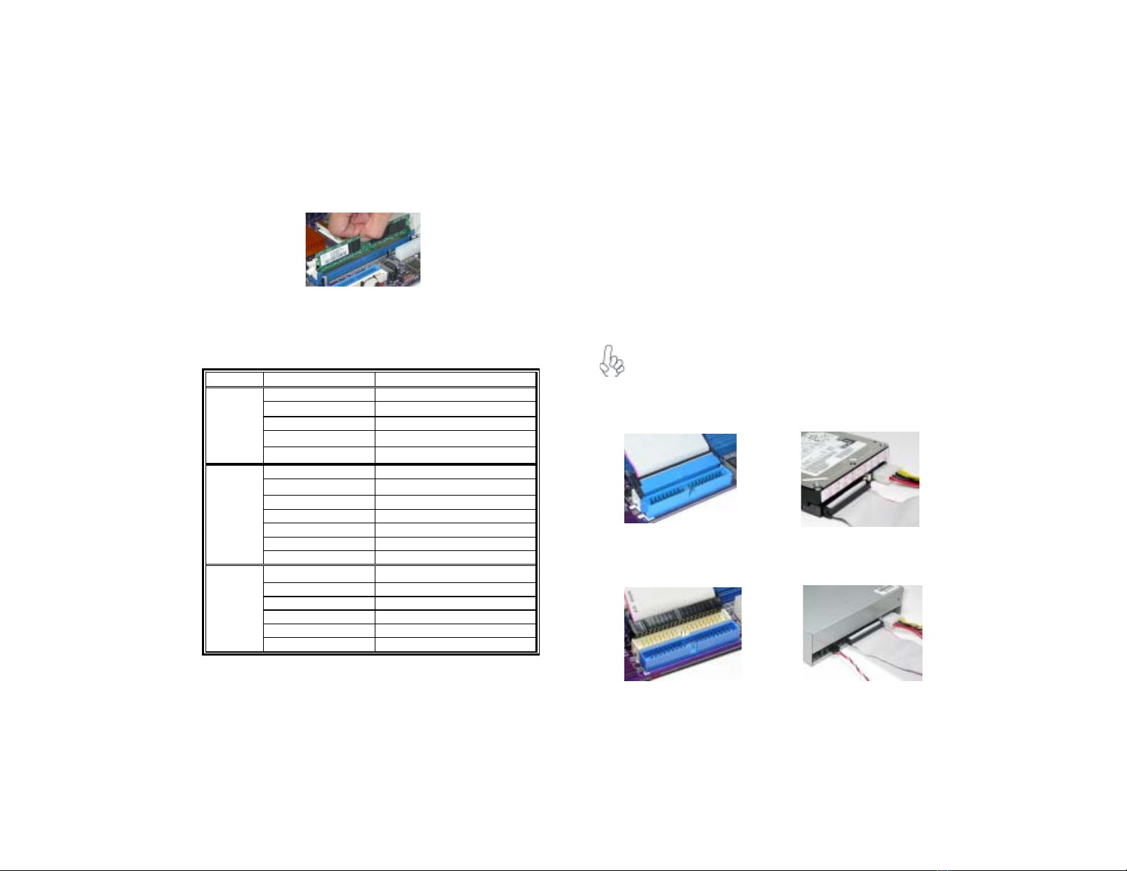
Installing a Hard Dish Drive/CD-ROM/SATA Hard
Drive
This section describes how to install IDE devices such as a hard disk drive and
a CD-ROM drive.
AboutIDE Devices
Your motherboard has a primary and secondary IDE channel interface (IDE1
and IDE2). An IDE ribbon cable supporting two IDE devices is bundled with
the motherboard.
You must orient the cable connector so that the pin1 (color) edge
of the cable correspoinds to the pin 1 of the I/O port connector.
IDE1: Primary IDE Connector
The first hard drive should always be connected to IDE1.
IDE2: Secondary IDE Connector
The second drive on this controller must be set to slave mode. The
cinfiguration is the same as IDE1.
Size Vendor Module Name
128MB SAMSUNG M368L1713DTM-CC4
Micron MT8VDDT1664AG-403B2
NANYA NT128D64SH4B1G-5
Infineon HYS64D16301GU-5-B
NANYA NT128D64SH4B1G-5T
256MB SAMSUNG M368L3223DTM-CC4
NANYA NT256D64S88B1G-5
Micron MT16VDDT3264AG-403B2
Infineon HYS64D32300GU-5-B
Micron MT8VDDT3264AG-40BC4
NANYA NT256D64S88B1G-5T
Infineon HYS64D32300HU-5-C
512MB SAMSUNG M368L6423DTM-CC4
NANYA NT512D64S8HB1G-5
Micron MT16VDDT6464AG-40BC4
NANYA NT512D64S8HB1G-5T
SAMSUNG M368L6423ETM-CC4
Infineon HYS64D64320HU-5-C
12
InstallingtheMotherboard
Installing a Floppy Diskette Drive
The motherboard has a floppy diskette drive (FDD) interface and ships with
a diskette drive ribbon cable that supports one or two floppy diskette drives.
You can install a 5.25-inch drive and a 3.5-inch drive with various capacities.
The floppy diskette drive cable has one type of connector for a 5.25-inch
drive and another type of connector for a 3.5-inch drive.
You must orient the cable connector so that the pin 1 (color)
edge of the cable corresponds to the pin 1 of the I/O port connec-
tor.
IDE devices enclose jumpers or switches used to set the IDE device as
MASTER or SLAVE. Refer to the IDE device user’s manual. Installing two
IDE devices on one cable, ensure that one device is set to MASTER and the
other device is set to SLAVE. The documentation of your IDE device ex-
plains how to do this.
AboutUltraDMA
This motherboard supports UltraDMA100/66. UDMA is a technology that
accelerates the performance of devices in the IDE channel. To maximize
performance, install IDE devices that support UDMA and use 80-pin IDE
cables that support UDMA 100/66.
AboutSATAConnectors
Your motherboard features two SATA connectors supporting a total of two
drives. SATA refers to Serial ATA (Advanced Technology Attachment) is the
standard interface for the IDE hard drives which are currently used in most
PCs. These connectors are well designed and will only fit in one orientation.
Locate the SATA connectors on the motherboard (see page 14) and follow
the illustration below to install the SATA hard drives.
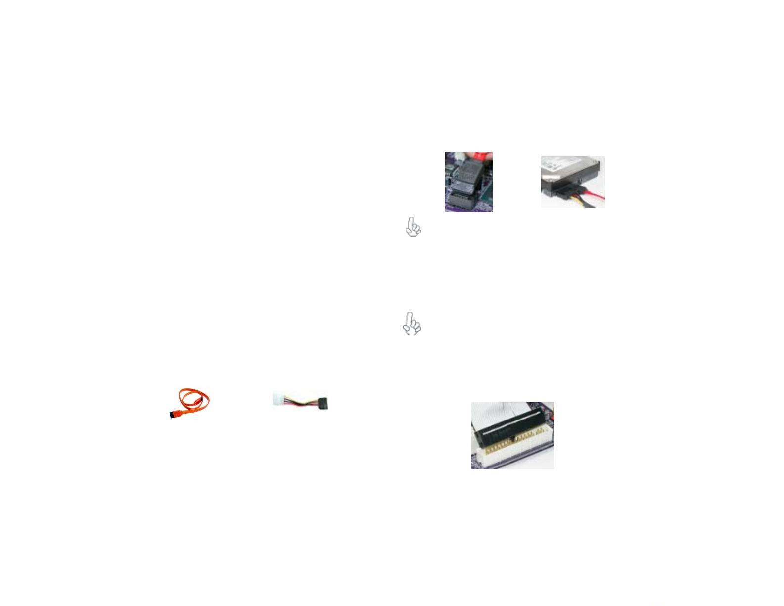
Installing SerialATAHard Drives
To install the Serial ATA (SATA) hard drives, use the SATA cable that sup-
ports the Serial ATA protocol. This SATA cable comes with an SATA power
cable. You can connect either end of the SATA cable to the SATA hard drive
or the connecter on the motherboard.
SATA cable (optional) SATA power cable (optional)
1. Refer to the illustration below for proper installation:
2. Attach either cable end to the connector on the motherboard.
3. Attach the other cable end to the SATA hard drive.
This motherboard does not support the “Hot-Plug” function.
FDD1:Floppy DiskConnector
This connector supports the provided floppy drive ribbon cable. After con-
necting the single end to the onboard floppy connector, connect the re-
maining plugs on the other end to the floppy drives correspondingly.
4. Attach the SATA power cable to the SATA hard drive and connect
the other end to the power supply.
13
InstallingtheMotherboard
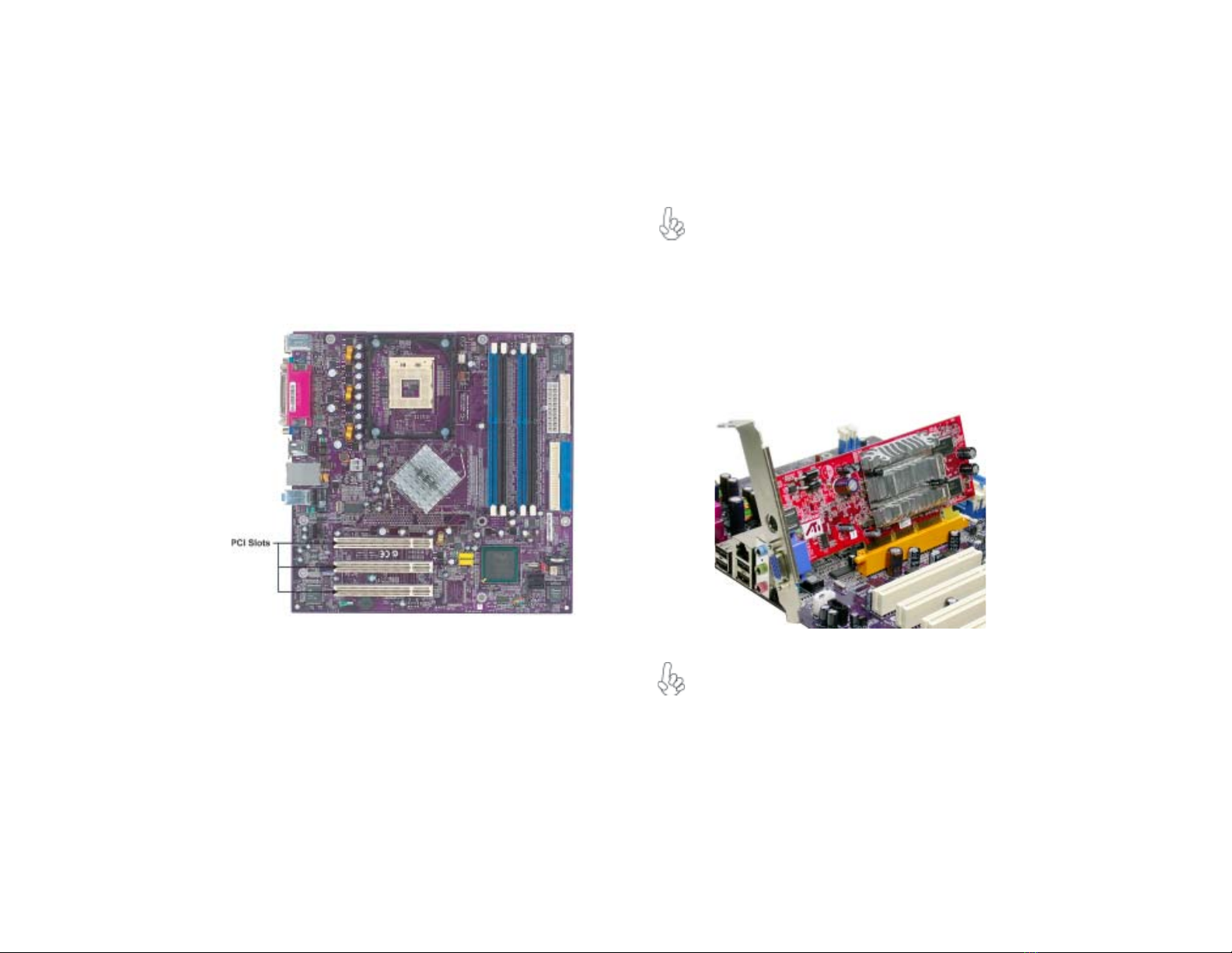
Installing Add-on Cards
The slots on this motherboard are designed to hold expansion cards and
connect them to the system bus. Expansion slots are a means of adding or
enhancing the motherboard’s features and capabilities. With these efficient
facilities, you can increase the motherboard’s capabilities by adding hardware
that performs tasks that are not part of the basic system.
Before installing an add-on card, check the documentation for
the card carefully. If the card is not Plug and Play, you may
have to manually configure the card before installation.
Follow these instructions to install an add-on card:
1. Remove a blanking plate from the system case corresponding to
the slot you are going to use.
2. Install the edge connector of the add-on card into the expansion
slot. Ensure that the edge connector is correctly seated in the
slot.
3. Secure the metal bracket of the card to the system case with a
screw.
For some add-on cards, for example graphics adapters and
network adapters, you have to install drivers and software be-
fore you can begin using the add-on card.
PCI Slot 865GV-M Deluxe is equipped with three standard PCI slots.
PCI stands for Peripheral Component Interconnect and is a
bus standard for expansion cards, which for the most part, is a
supplement of the older ISA bus standard. The PCI slots on
this board are PCI v2.3 compliant.
Table of contents
Other ECS Motherboard manuals

ECS
ECS H61H2-M16 User manual

ECS
ECS Motherboard User manual

ECS
ECS X48T-A User manual

ECS
ECS G41T-M7 User manual

ECS
ECS P965T-A User manual

ECS
ECS Motherboard User manual

ECS
ECS Z87H3-A2X EXTREME GOLDEN User manual

ECS
ECS B75H2-M3 User manual

ECS
ECS A890GXM-A2 User manual

ECS
ECS GeForce 6100PM-M2 User manual


Popular Motherboard manuals by other brands


 user manual")


Gigabyte
Gigabyte GA-H81M-WW user manual

Supero
Supero X10SLH-F user manual

Electrorad
Electrorad 4 Zones RF Programmer Installation & operation manual

Texas Instruments
Texas Instruments TMAG5 73 Series user guide

Texas Instruments
Texas Instruments AN-1966 LMH2190 user guide

Intel
Intel D845PESV Specification update