ECS 761GXM-M2 User manual


Preface
Preface
Copyright
This publication, including all photographs, illustrations and software, is protected
under international copyright laws, with all rights reserved. Neither this manual, nor
any of the material contained herein, may be reproduced without written consent of
the author.
Version 1.0
Disclaimer
The information in this document is subject to change without notice. The manufac-
turer makes no representations or warranties with respect to the contents hereof and
specifically disclaims any implied warranties of merchantability or fitness for any
particular purpose. The manufacturer reserves the right to revise this publication and
to make changes from time to time in the content hereof without obligation of the
manufacturer to notify any person of such revision or changes.
TrademarkRecognition
Microsoft, MS-DOS and Windows are registered trademarks of Microsoft Corp.
AMD, Athlon, Sempron and Duron are registered trademarks of AMD Corporation.
Other product names used in this manual are the properties of their respective
owners and are acknowledged.
FederalCommunicationsCommission(FCC)
This equipment has been tested and found to comply with the limits for a Class B
digital device, pursuant to Part 15 of the FCC Rules. These limits are designed to
provide reasonable protection against harmful interference in a residential installa-
tion. This equipment generates, uses, and can radiate radio frequency energy and, if
not installed and used in accordance with the instructions, may cause harmful inter-
ference to radio communications. However, there is no guarantee that interference
will not occur in a particular installation. If this equipment does cause harmful
interference to radio or television reception, which can be determined by turning the
equipment off and on, the user is encouraged to try to correct the interference by one
or more of the following measures:
• Reorient or relocate the receiving antenna
• Increase the separation between the equipment and the receiver
• Connect the equipment onto an outlet on a circuit different from that to
which the receiver is connected
• Consult the dealer or an experienced radio/TV technician for help
Shielded interconnect cables and a shielded AC power cable must be employed with
this equipment to ensure compliance with the pertinent RF emission limits govern-
ing this device. Changes or modifications not expressly approved by the system’s
manufacturer could void the user’s authority to operate the equipment.

ii
Preface
DeclarationofConformity
This device complies with part 15 of the FCC rules. Operation is subject to the
following conditions:
• This device may not cause harmful interference, and
• This device must accept any interference received, including interfer-
ence that may cause undesired operation
CanadianDepartmentofCommunications
This class B digital apparatus meets all requirements of the Canadian Interference-
causing Equipment Regulations.
Cet appareil numérique de la classe B respecte toutes les exigences du Réglement sur
le matériel brouilieur du Canada.
AbouttheManual
The manual consists of the following:
Chapter 1
Introducing the Motherboard
Chapter 2
Installing the Motherboard
Chapter 3
UsingBIOS
Chapter 4
Using the Motherboard Soft-
ware
Chapter 5
SIS965LSATARAIDSetupGuide
Describes features of the
motherboard.
Describes installation of
motherboard components.
Goto Hpage 7
Provides information on using the
BIOS Setup Utility.
Go to Hpage 27
Describes the motherboard soft-
ware
Go to Hpage 39
Go to Hpage 1
Provides information about SATA
RAID Setup
Go to Hpage 43

iii
TT
TT
TABLE OF CONTENTSABLE OF CONTENTS
ABLE OF CONTENTSABLE OF CONTENTS
ABLE OF CONTENTS
Preface i
Chapter 1 1
IntroducingtheMotherboard 1
Introduction................................................................................................1
Features.............................................................................................2
Motherboard Components............................................................4
Chapter 2 77
77
7
Installing the Motherboard 7
SafetyPrecautions...........................................................................7
Choosinga ComputerCase............................................................7
Installingthe Motherboard ina Case............................................7
CheckingJumperSettings...............................................................8
Setting Jumpers...................................................................8
Checking Jumper Settings...................................................9
Jumper Settings...................................................................9
ConnectingCase Components.....................................................10
Front PanelHeader...........................................................12
InstallingHardware........................................................................13
Installing the Processor.....................................................13
Installing Memory Modules...............................................15
Installinga Hard Disk Drive/CD-ROM/SATAHard Drive...18
Installing a Floppy Diskette Drive....................................20
Installing Add-on Cards...................................................21
Connecting Optional Devices ...........................................23
ConnectingI/ODevices................................................................26
Chapter 3 2727
2727
27
UsingBIOS 27
Aboutthe SetupUtility.................................................................27
The Standard Configuration..............................................27
Entering the Setup Utility...................................................27
Updating the BIOS............................................................29
UsingBIOS......................................................................................29
Standard CMOS Setup.......................................................30
Advanced Setup.................................................................31
Features Setup...................................................................32

iv
Power Management Setup...........................................................34
PCI/Plug and Play Setup.............................................................35
BIOS Security Features................................................................36
CPU PnP Setup............................................................................36
Hardware Monitor.......................................................................37
Load Optimal Defaults.................................................................38
Save Changes and Exit.................................................................38
Discard Changes and Exit ..........................................................38
Chapter 4 3939
3939
39
UsingtheMotherboardSoftware 39
Aboutthe SoftwareCD-ROM......................................................39
Auto-installingunderWindows 2000/XP...................................39
Running Setup....................................................................40
ManualInstallation........................................................................42
UtilitySoftware Reference ..........................................................42
Chapter 5 4343
4343
43
SIS965LSATARAIDSetupGuide 43
Introductionfor SiS965LSATARAIDFunction.......................43
Features..........................................................................................43
SupportOperating Systems.........................................................43
What isRAID ................................................................................43
Installing SoftwareDrivers..........................................................44
BIOSUtilityOperation..................................................................45

1
IntroducingtheMotherboard
Chapter1
IntroducingtheMotherboard
Introduction
Thank you for choosing the 761GXM-M2 motherboard. This motherboard is a high
performance, enhanced function motherboard that supports Socket AM2 for AMD
Athlon 64 FX/Athlon 64 X2 Dual-Core/Athlon 64/Sempron processors for high-end
business or personal desktop markets.
The motherboard incorporates the SiS761GX Northbridge (NB) and SiS965L
Southbridge (SB) chipsets. The SiS761GX Northbridge on this motherboard features
the HyperTranportTM complaint bus driver technology to support AMD Athlon 64
FX/Athlon 64 X2 Dual-Core/Athlon 64/Sempron processors up to 2000 MT/s data
rate. The Northbridge supports integrated Host-to-PCI Express Bridge, compliant
with PCI Express Spec. 1.0a. Plus, SiS MuTIOL, a high bandwidth and mature tech-
nology, is incorporated to connect SiS761GX and SiS965L MuTIOL Media I/O
together.
The SiS965L Southbridge on this motherboard supports Hi-Precision Event Timer
(HPET) for Microsoft Windows with multiple DMA bus architecture that supports
isochronous request and continuous packet transmission. It implements an EHCI
compliant interface that supports up to eight USB 2.0 ports. The Southbridge inte-
grates a Serial ATA host controller supporting two SATA ports with maximum trans-
fer rate up to 1.5 Gb/s.
There is an advanced full set of I/O ports in the rear panel, including PS/2 mouse and
keyboard connectors, COM1, LPT1, one VGA port and four USB ports, one optional
LAN port, and audio jacks for microphone, line-in, and line-out.

2
IntroducingtheMotherboard
Feature
Processor
The SiS761GX Northbridge (NB) and SiS965L Southbridge (SB) chipsets are
based on an innovative and scalable architecture with proven reliability and
performance.
SiS761GX
(NB)
• SiS MuTIOL is incorporated to connect SiS761GX and
SiS965LMuTIOL Media I/O
• Supports HyperTransportTM Technology up to 2000 MT/s
bandwidth
• Integrated MuTIOL 1G to PCI Express x1 Bridge, compliant
with PCI Express spec.1.0a
• Supports up to 128 MB display memory with shared sys-
tem memory
• High Performance & High quality 3D/2D Graphics Accel-
erator
Chipset
HyperTransportTM Technology is a point-to-point link between two devices, it en-
ables integrated circuits to exchange information at much higher speeds than cur-
rently available interconnect technologies.
SiS965L
(SB)
• Integrated Multi-threaded I/O link Ensures Concurrency of
Upstream/down Stream Data Transfer with 1.2 GB/s Band-
width
• Compliant with PCI 2.3 specification supporting up to 6 PCI
masters
• Compliant with PCI Express 1.0a
• Compliant with Serial ATA 1.0 specification
• Supports Dual IDE Master/Slave Controller supports Ultra
DMA133/100/66/33
• Integrated USB 2.0 Controller supporting up to eight ports
This motherboard uses socket AM2 that carries the following features:
Memory
• Supports DDR2 800/667/533/400 DDR SDRAM with Dual-channel
achitecture
• Accommodates two unbuffered DIMMs, with maximum memory size
up to 16 GB
Onboard LAN (optional)
The onboard LAN provides the following features:
•AccommodatesAMDAthlon 64FX/Athlon 64 X2Dual-Core/Athlon 64/
Sempron processors
• Supports up to 2000 MT/s HyperTransportTM (HT) interface speeds
• Supports 10BASE-T/100BASE-TX IEEE 802.3u fast Ethernet trans-
ceiver
• Integrated voltage regulator to allow operation from a single 3.3 V/
2.5V supply source
• Supports MII and 7-wire serial interface
• Supports low-power mode

3
IntroducingtheMotherboard
The motherboard comes with the following expansion options:
• One PCI Express x16 slot for Graphics interface
• One PCI Express x1 slot
• Two 32-bit PCI slots
• One CNR slot (optional)
• Two IDE connectors which support four IDE devices
• One floppy disk drive interface
• Two 7-pin SATA connectors
This motherboard supports Ultra DMA bus mastering with transfer rates of 133/
100/66 MB/s.
Expansion Options
Audio
• CompliantwithAC’97 v2.3 CODEC
• Supports 6-channel audio CODEC designed for PC multimedia sys-
tems
• Provides three analog line-level stereo input with 5-bit volume control:
Line-in,CD,AUX
• Meets Microsoft WHQL/WLP 2.0 audio requirements
Some hardware specifications and software items are subject to change
without prior notice.
BIOS Firmware
The motherboard uses AMI BIOS that enables users to configure many system
features including the following:
• Power management
• Wake-up alarms
• CPUparameters
• CPUandmemorytiming
The firmware can also be used to set parameters for different processor clock
speeds.
Integrated I/O
The motherboard has a full set of I/O ports and connectors:
• Two PS/2 ports for mouse and keyboard
• One serial port
• One parallel port
• One VGA port
• Four USB ports
• One LAN port (optional)
• Audio jacks for microphone, line-in and line-out
4
IntroducingtheMotherboard
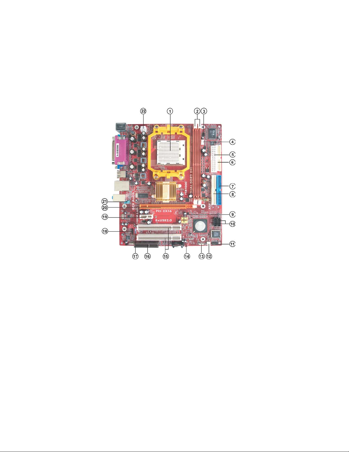
MotherboardComponents
5
IntroducingtheMotherboard
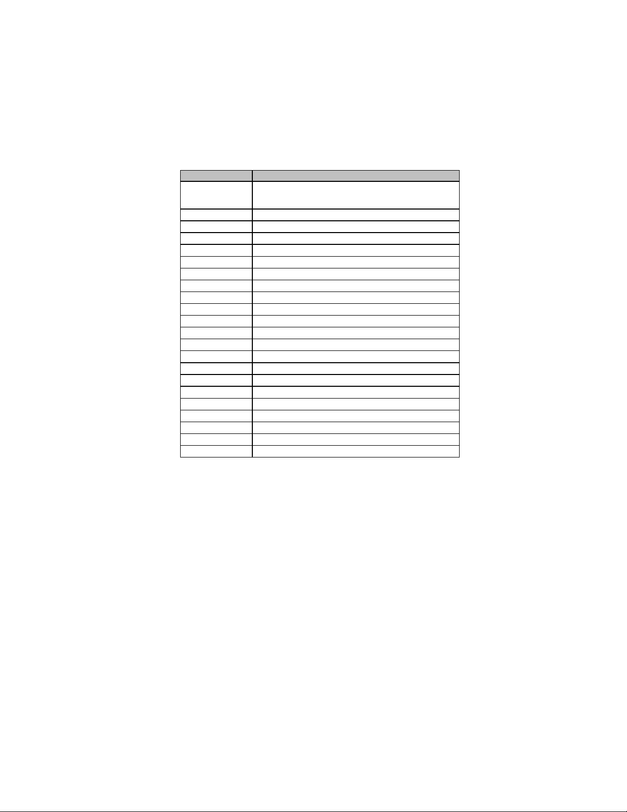
Table of Motherboard Components
This concludes Chapter 1. The next chapter explains how to install the motherboard.
“*” stands for optional components
LABE
L
COMPONENTS
1. CPU Socket Socket AM2 for AMD Athlon 64 FX/Athlon 64
X2 Dual-Core/Athlon 64/Sempron CPUs
2. DDRII1~2 240-pin DDR2 SDRAM slots
3. IR1 Infrared header
4. CPU_FAN1 CPU cooling fan connector
5. PWR1 Standard 24-Pin ATX Power connector
6. FDD1 Floppy Disk Drive connector
7. IDE1 Primary IDE connector
8. IDE2 Secondary IDE connector
9. F_USB1~2 Front Panel USB headers
10. SATA1~2 Serial ATA connectors
11. PANEL1 Front panel switch/LED header
12. SYS_FAN1 System Fan connector
13. SPK1 Speaker header
14. CLR_CMOS1 Clear CMOS jumper
15. PCI1~2 32-bit add-on card slots
16. CNR1* CNR slot
17. SPDIFO1 SPDIF out header
18. CD_IN1 Analog audio input connecor
19. PCI-E2 PCI Express x1 slot
20. PCI-E1 PCI Express x16 slot for graphics interface
21. F_AUDIO1 Front Panel Audio header
22. PWR2 4-pin +12V power connector

6
IntroducingtheMotherboard
Memo

7
InstallingtheMotherboard
Chapter2
InstallingtheMotherboard
SafetyPrecautions
• Follow these safety precautions when installing the motherboard
• Wear a grounding strap attached to a grounded device to avoid dam-
age from static electricity
• Discharge static electricity by touching the metal case of a safely
grounded object before working on the motherboard
• Leave components in the static-proof bags they came in
• Hold all circuit boards by the edges. Do not bend circuit boards
ChoosingaComputer Case
There are many types of computer cases on the market. The motherboard complies
with the specifications for the Micro ATX system case. Firstly, some features on the
motherboard are implemented by cabling connectors on the motherboard to indica-
tors and switches on the system case. Make sure that your case supports all the
features required. Secondly, this motherboard supports one floppy controller and
four enhanced IDE drives. Make sure that your case has sufficient power and space
for all drives that you intend to install.
Most cases have a choice of I/O templates in the rear panel. Make sure that the I/O
template in the case matches the I/O ports installed on the rear edge of the
motherboard.
This motherboard carries a Micro ATX form factor of 244 X 200 mm. Choose a case
that accommodates this form factor.
InstallingtheMotherboardin aCase
Refer to the following illustration and instructions for installing the motherboard in
a case.
Most system cases have mounting brackets installed in the case, which correspond
the holes in the motherboard. Place the motherboard over the mounting brackets
and secure the motherboard onto the mounting brackets with screws.
Ensure that your case has an I/O template that supports the I/O ports and expansion
slots on your motherboard.

8
InstallingtheMotherboard
CheckingJumperSettings
This section explains how to set jumpers for correct configuration of the motherboard.
SettingJumpers
Use the motherboard jumpers to set system configuration options. Jumpers with
more than one pin are numbered. When setting the jumpers, ensure that the jumper
caps are placed on the correct pins.
The illustrations show a 2-pin jumper. When
the jumper cap is placed on both pins, the
jumper is SHORT. If you remove the jumper
cap, or place the jumper cap on just one pin,
the jumper is OPEN.
This illustration shows a 3-pin jumper. Pins
1 and 2 are SHORT.
SHORT OPEN
Do not overtighten the screws as this can stress the motherboard.
9
InstallingtheMotherboard
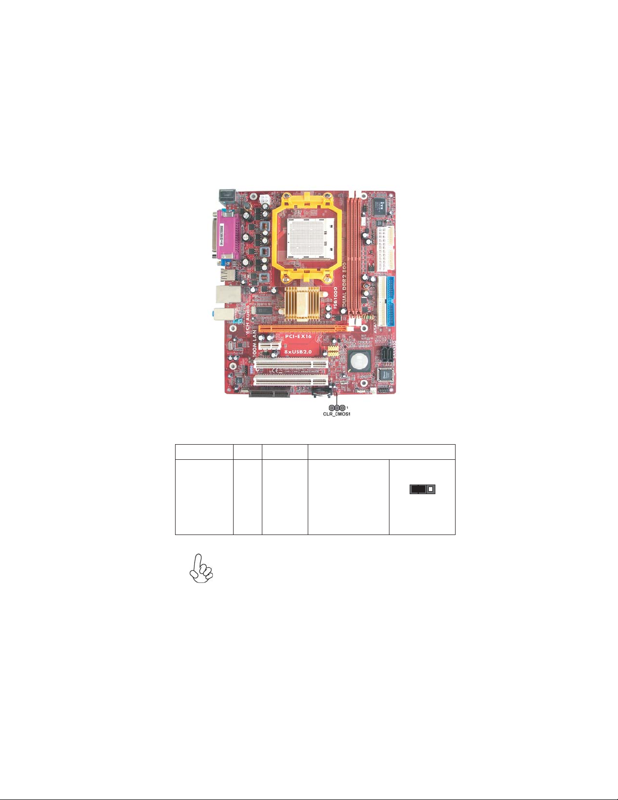
Checking Jumper Settings
The following illustration shows the location of the motherboard jumpers. Pin 1 is
labeled.
JumperSettings
Jumper Type Description Setting (default)
CLR_CMOS1 3-pin Clear CMOS
1-2: CLEAR CMOS
2-3: NORMAL
Before clearing the
CMOS, make sure to
turn off the system.
1
CLR_CMOS1
To avoid the system unstability after clearing CMOS, we recom-
mend users to enter the main BIOS setting page to “Load Optimal
Defaults” and then “Save Changes and Exit”.

10
InstallingtheMotherboard
ConnectingCaseComponents
After you have installed the motherboard into a case, you can begin connecting the
motherboard components. Refer to the following:
1 Connect the CPU cooling fan cable to CPU_FAN1.
2 Connect the system cooling fan connector to SYS_FAN1.
3 Connect the case switches and indicator LEDs to the PANEL1.
4 Connect the standard power supply connector to PWR1.
5 Connect the auxiliary case power supply connector to PWR2.
6 Connect the case speaker cable to SPK1.
Connecting 20/24-pin power cable
Users please note that the 20-pin and 24-pin power cables can both be
connected to the PWR1 connector. With the 20-pin power cable, just align
the 20-pin power cable with the pin 1 of the PWR1 connector. However,
using 20-pin power cable may cause the system to become unbootable or
unstable because of insufficient electricity. A minimum power of 300W is
recommended for a fully-configured system.
With ATX v2.x power supply, users please note
that when installing 24-pin power cable, the
latches of power cable cling to the right side of
PWR1 connector latch.
With ATX v1.x power supply, users please note
that when installing 20-pin power cable, the
latch of power cable falls on the left side of the
PWR1 connector latch, just as the picture
shows.
20-pin power cable
24-pin power cable

11
InstallingtheMotherboard
PWR2:ATX 12V Power Connector
PWR1:ATX 24-pin Power Connector
CPU_FAN1:CPU coolingFan Power Connector
Users please note that the fan connector supports the CPU cooling fan of
1.1A ~ 2.2A (26.4W max) at +12V.
1 GND System Ground
2 +12V Power +12V
3 Sense Sense
4 Control Control
Pin Signal Name Function
1+3.3V 13 +3.3V
2+3.3V 14 -12V
3Ground 15 Ground
4+5V 16 PS_ON
5Ground 17 Ground
6+5V 18 Ground
7Ground 19 Ground
8PWRGD 20 -5V
9+5VSB 21 +5V
10 +12V 22 +5V
11 +12V 23 +5V
12 +3.3V 24 Ground
Pin Signal Name Pin Signal Name
Pin Signal Name
4+12V
3+12V
2Ground
1Ground
SYS_FAN1: FANPowerConnectors
1 GND System Ground
2 +12V Power +12V
3 Sense Sensor
Pin Signal Name Function
12
InstallingtheMotherboard
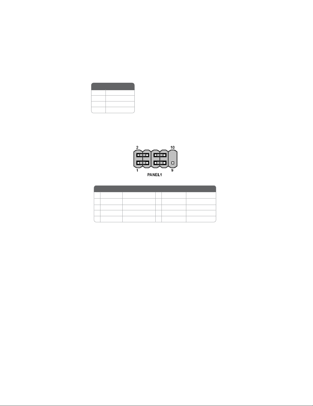
Front Panel Header
The front panel header (PANEL1) provides a standard set of switch and LED headers
commonly found on ATX or Micro ATX cases. Refer to the table below for informa-
tion:
Reset Switch
Supporting the reset function requires connecting pin 5 and 7 to a momentary-
contact switch that is normally open. When the switch is closed, the board resets and
runs POST.
Power/Sleep/Message waiting LED
Connecting pins 2 and 4 to a single or dual-color, front panel mounted LED provides
power on/off, sleep, and message waiting indication.
Hard Drive Activity LED
Connecting pins 1 and 3 to a front panel mounted LED provides visual indication
that data is being read from or written to the hard drive. For the LED to function
properly, an IDE drive should be connected to the onboard IDE interface. The LED
will also show activity for devices connected to the SCSI (hard drive activity LED)
connector.
Pin Signal Name Function
1 HD_LED_P Hard disk LED(+) 2 FP PWR/SLP *MSG LED(+)
3 HD_LED_N Hard disk LED(-)
5 RST _SW_N Reset Switch(-)
7 RST_SW_P Reset Switch(+)
9 RSVD Reserved
4 FP PWR/SLP *MSG LED(-)
6 PWR_SW_P Power Switch(+)
8 PWR_SW_N Power Switch(-)
10 Key No pin
* MSG LED (dual color or single color)
Pin Signal Name Function
SPK1: Internal speaker
Pin Signal Name
4SPKR
3GND
2NC
1+5V

13
InstallingtheMotherboard
InstallingHardware
Installing the Processor
Caution: When installing a CPU heatsink and cooling fan make sure that
you DO NOT scratch the motherboard or any of the surface-mount
resistors with the clip of the cooling fan. If the clip of the cooling fan
scrapes across the motherboard, you may cause serious damage to the
motherboard or its components.
On most motherboards, there are small surface-mount resistors near the
processor socket, which may be damaged if the cooling fan is carelessly
installed.
Avoid using cooling fans with sharp edges on the fan casing and the clips.
Also, install the cooling fan in a well-lit work area so that you can clearly
see the motherboard and processor socket.
Before installing the Processor
This motherboard automatically determines the CPU clock frequency and system
bus frequency for the processor. You may be able to change these settings by making
changes to jumpers on the motherboard, or changing the settings in the system Setup
Utility. We strongly recommend that you do not over-clock processors or other
components to run faster than their rated speed.
This motherboard has an Socket AM2. When choosing a processor, consider the
performance requirements of the system. Performance is based on the processor
design, the clock speed and system bus frequency of the processor, and the quantity
of internal cache memory and external cache memory.
Warning: Over-clocking components can adversely affect the reliability of
the system and introduce errors into your system. Over-clocking can
permanently damage the motherboard by generating excess heat in
components that are run beyond the rated limits.
Power Switch
Supporting the power on/off function requires connecting pins 6 and 8 to a momen-
tary-contact switch that is normally open. The switch should maintain contact for
at least 50 ms to signal the power supply to switch on or off. The time requirement
is due to internal de-bounce circuitry. After receiving a power on/off signal, at least
two seconds elapses before the power supply recognizes another on/off signal.
14
InstallingtheMotherboard
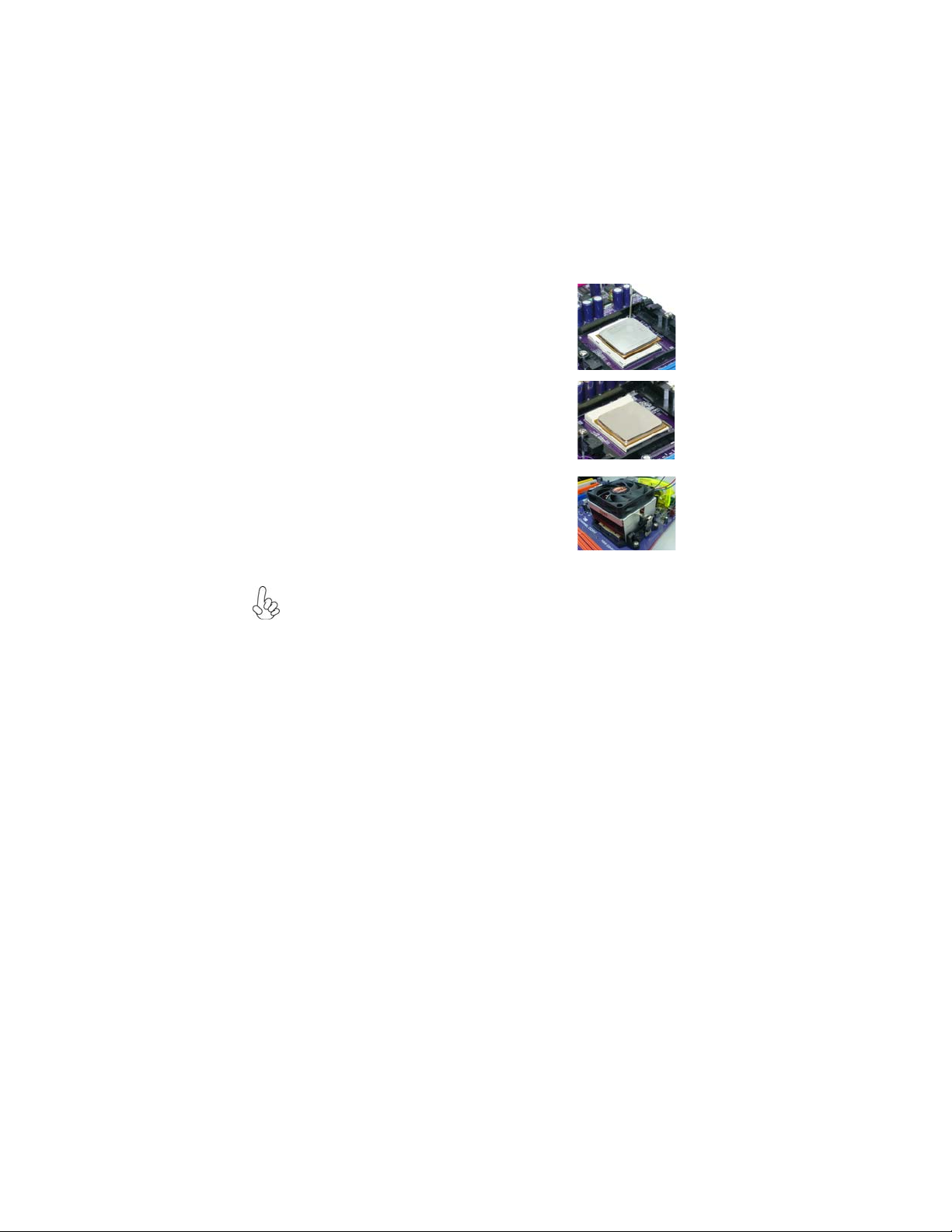
1 Install your CPU. Pull up the lever away from the
socket and lift up to 90-degree angle.
2 Locate the CPU cut edge (the corner with the pin
hold noticeably missing). Align and insert the CPU
correctly.
3 Press the lever down and apply thermal grease on
top of the CPU.
4 Put the CPU Fan down on the retention module and
snap the four retention legs of the cooling fan into
place.
5 Flip thelevers over to lockthe heatsink in placeand
connect the CPU cooling Fan power cable to the
CPUFAN connector. Thiscompletes the installation.
CPU Installation Procedure
The following illustration shows CPU installation components.
To achieve better airflow rates and heat dissipation, we suggest that you use
a high quality fan with 4800 rpm at least. CPU fan and heatsink installation
procedures may vary with the type of CPU fan/heatsink supplied. The form
and size of fan/heatsink may also vary.
Table of contents
Other ECS Motherboard manuals


Popular Motherboard manuals by other brands


Renesas
Renesas RE01 15000KB quick start guide

Freescale Semiconductor
Freescale Semiconductor TWR-MPC5125 quick start guide

Asus
Asus MAXIMUS VI EXTREME user manual

ASROCK
ASROCK Z390M-ITX/ac user manual

Texas Instruments
Texas Instruments bq76PL536A quick start guide

NXP Semiconductors
NXP Semiconductors MPC8349E-mITX-GP user guide


