Advansus MX965Q2 User manual
MX965Q2
Intel®Q965 LGA775 Core™ 2 Extreme / Core™ 2 Quad/
Core™ 2 Duo / Core™ Duo Micro ATX Main Board
User’s Manual
Ver. 1.00

MX965Q2
2
Contents
Safety Information ..........................................................................................................5
Technical Support ............................................................................................................6
Conventions Used in This Guide....................................................................................6
Disclaimer and Notice .....................................................................................................6
Packing List.......................................................................................................................7
Revision History ...............................................................................................................8
Specifications Summary..................................................................................................9
Block Diagram.................................................................................................................12
Production Introduction ...............................................................................................14
1.1 Before you Proceed ................................................................................................14
1.2 Motherboard Overview............................................................................................15
1.2.1 Placement Direction....................................................................................................................... 15
1.2.2 Screw Holes................................................................................................................................... 15
1.3 Motherboard Layout................................................................................................16
1.3.1 Layout Content List ........................................................................................................................ 17
1.4 Central Processing Unit (CPU)................................................................................19
1.4.1 Installing the CPU........................................................................................................................... 20
1.4.2 Installing the CPU Heatsink and Fan.............................................................................................22
1.4.3 Uninstalling the CPU Heatsink and Fan......................................................................................... 24
1.5 System Memory......................................................................................................26
1.5.1 DIMM Sockets Location ................................................................................................................. 26
1.5.2 Memory Configurations.................................................................................................................. 27
1.5.3 Installing a DDR2 DIMM................................................................................................................. 28
1.5.4 Removing a DDR2 DIMM............................................................................................................... 28
1.6 Expansion Slots ......................................................................................................29
1.6.1 Installing an Expansion Card ......................................................................................................... 29
1.6.2 Configuring an Expansion Card..................................................................................................... 29
1.6.3 Standard Interrupt Assignments..................................................................................................... 30
1.6.4 PCI Slots ........................................................................................................................................ 31
1.6.5 PCI Express X16 Slot..................................................................................................................... 31

User’s Manual
MX965Q2
3
Contents
1.7 Jumpers..................................................................................................................32
1.7.1 Clear CMOS (CLRTC).................................................................................................................... 32
1.8 Connectors..............................................................................................................33
1.8.1 Rear Panel Connectors.................................................................................................................. 33
1.8.2 Front Panel Audio Connector (AAFP1).......................................................................................... 36
1.8.3 ATX Power Connector (ATX12V, EATXPWR)............................................................................... 37
1.8.4 Optical Drive Audio Connector (CD)..............................................................................................38
1.8.5 Serial Port 2 Connector (COM2).................................................................................................... 38
1.8.6 Serial Port 3 Connector (COM3).................................................................................................... 39
1.8.7 Serial Port 4 Connector (COM4).................................................................................................... 39
1.8.8 Chassis Intrusion Connector (CHASSIS)....................................................................................... 40
1.8.9 Chassis Fan Connector 1 (CHA_FAN) .......................................................................................... 40
1.8.10 Chassis Fan Connector 2 (CHA_FAN2).................................................................................... 41
1.8.11 CPU Fan Connector (CPU_FAN).............................................................................................. 41
1.8.12 System Panel Connector (F_PANEL)........................................................................................ 42
1.8.13 SPI Connector (JSPI)................................................................................................................. 43
1.8.14 Primary IDE Connector (PRI_EIDE1)........................................................................................ 43
1.8.15 Power Fan Connector (PWR_FAN)........................................................................................... 44
1.8.16 Serial ATA Connector [Red] (SATA1, SATA2).......................................................................... 44
1.8.17 Digital Audio Connector (SPDIF_OUT1) ................................................................................... 45
1.8.18 USB 2.0 Connector (USB56)..................................................................................................... 46

MX965Q2
4
Contents
BIOS Setup......................................................................................................................48
2.1 BIOS Setup Program ..............................................................................................48
2.1.1 Legend Box.................................................................................................................................... 49
2.1.2 List Box........................................................................................................................................... 49
2.1.3 Sub-menu....................................................................................................................................... 49
2.2 BIOS Menu Screen.................................................................................................50
2.2.1 Standard CMOS Features.............................................................................................................. 51
2.2.2 Advanced BIOS Features .............................................................................................................. 53
2.2.3 Advanced Chipset Features........................................................................................................... 59
2.2.4 Integrated Peripherals.................................................................................................................... 61
2.2.5 Security Chip Configuration ........................................................................................................... 67
2.2.6 Power Management Setup............................................................................................................. 68
2.2.7 PnP/PCI Configurations ................................................................................................................. 71
2.2.8 PC Health Status............................................................................................................................ 73
2.2.9 Frequency/Voltage Control ............................................................................................................ 75
2.2.10 Load Fail-Safe Defaults ............................................................................................................. 76
2.2.11 Load Optimized Defaults............................................................................................................ 77
2.2.12 Set Supervisor Password........................................................................................................... 78
2.2.13 Set User Password.................................................................................................................... 79
2.2.14 Save and Exit Setup .................................................................................................................. 80
2.2.15 Exit Without Saving.................................................................................................................... 81

User’s Manual
MX965Q2
5
Safety Information
Electrical safety
zTo prevent electrical shock hazard, disconnect the power cable from the electrical
outlet before relocating the system.
zWhen adding or removing devices to or from the system, ensure that the power cables
for the devices are unplugged before the signal cables are connected. If possible,
disconnect all power cables from the existing system before you add a device.
zBefore connecting or removing signal cables from the motherboard, ensure that all
power cables are unplugged.
zSeek professional assistance before using an adapter or extension cord. These
devices could interrupt the grounding circuit.
zMake sure that your power supply is set to the correct voltage in your area. If you are
not sure about the voltage of the electrical outlet you are using, contact your local
power company.
zIf the power supply is broken, do not try to fix it by yourself. Contact a qualified service
technician or your retailer.
Operation safety
zBefore installing the motherboard and adding devices on it, carefully read all the
manuals that came with the package.
zBefore using the product, make sure all cables are correctly connected and the power
cables are not damaged. If you detect any damage, contact your dealer immediately.
zTo avoid short circuits, keep paper clips, screws, and staples away from connectors,
slots, sockets and circuitry.
zAvoid dust, humidity, and temperature extremes. Do not place the product in any area
where it may become wet.
zPlace the product on a stable surface.
zIf you encounter technical problems with the product, contact a qualified service
technician or your retailer.
The symbol of the crossed out wheeled bin indicates that the product
(electrical and electronic equipment) should not be placed in
municipal waste. Check local regulations for disposal of electronic
products.
MX965Q2
6
Technical Support
If a problem arises with your system and no solution can be obtained from the user’s
manual, please contact your place of purchase or local distributor. Alternatively, please try
the following help resources for further guidance. Visit the Advansus website for FAQ,
technical guide, BIOS updates, driver updates, and other information:
http://www.advansus.com.tw/Support/Support.asp
Conventions Used in This Guide
To make sure that you perform certain tasks properly, take note of the following symbols
used throughout this manual.
DANGER/WARNING: Information to prevent injury to yourself when
trying to complete a task.
CAUTION: Information to prevent damage to the components when
trying to complete a task.
IMPORTANT: Instructions that you MUST follow to complete a task.
NOTE: Tips and additional information to help you complete a task.
Disclaimer and Notice
The manufacturer reserves the right to make changes, without notice, to any product,
including circuits and/or software described or contained in this manual in order to improve
design and/or performance. The manufacturer assumes no responsibility or liability for the
use of the described product(s), conveys no license or title under any patent, copyright, or
masks work rights to these products, and makes no representations or warranties that
these products are free from patent, copyright, or mask work right infringement, unless
otherwise specified. For the detail product information, please refer to user’s manual.

User’s Manual
MX965Q2
7
Packing List
Before you begin installing your single board, please make sure that the following materials
have been shipped:
91 x Intel Q965 Micro ATX Main board
91 x CD-ROM contains the followings:
-User’s manual (this manual in PDF file)
-Drivers
91 x 2-in-1 FD/ATA cable
93 x COM1 cable (9-pin, 260mm)
92 x SATA cable
91 x Startup Manual
If any of the above items is damaged or missing, please contact your
retailer.

MX965Q2
8
Revision History
Revision Revision History Date
V 1.0 First release for PCB 1.00 March 25, 2008
User’s Manual
MX965Q2
9
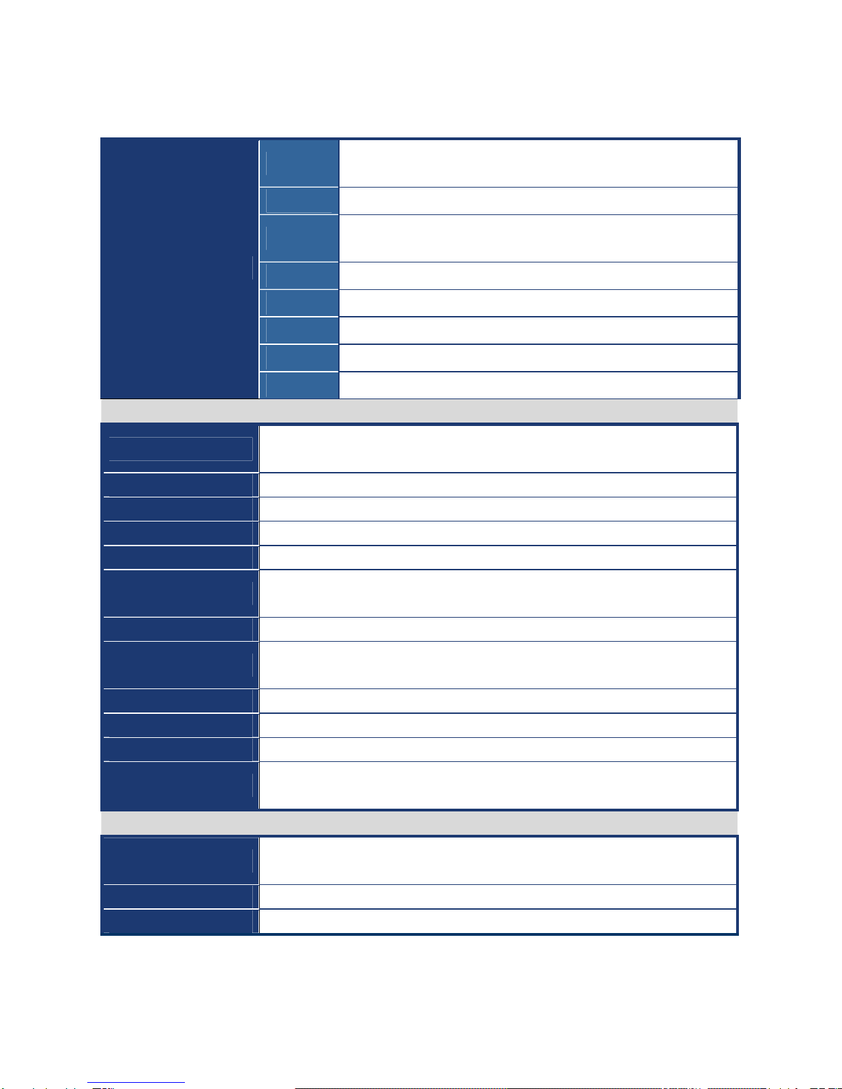
Specifications Summary
CPU Supports Intel LGA775 Core 2 Extreme / Core 2 Quad / Core 2 Duo
/ Core Duo / Pentium 4 / Celeron D with 65nm process technology
Chipset Intel 82Q965 Chipset
Memory Four 240-pin DIMMs up to 8 GB Dual Channel DDR2 800/667/533
SDRAM
Graphic Intel Graphics Media Accelerator 3000
Audio Realtek ALC888 7.1 Ch. + 2 Ch. High Definition Audio Codec
LAN Realtek RTL8111B Gigabit LAN
Expansion 1 x PCI-E X16, 3 x PCI 2.2
Features
I/O 4 x COM, 6 x USB 2.0, 2 x SATA/SATA II
System
CPU Supports Intel LGA775 Core 2 Extreme / Core 2 Quad / Core 2 Duo / Core Duo /
Pentium 4 / Celeron D with 65nm process technology
FSB 1066/800/533 MHz
BIOS Award 16 Mb SPI BIOS
System Chipset Intel 82Q965 GMCH/ICH8
I/O Chipset Winbond W83627DHG-A
Memory Four 240-pin DIMM sockets support up to 8 GB Dual Channel DDR2 800/667/533
SDRAM
Watchdog Timer Reset: 1 sec.~255 min. and 1 sec. or 1 min./step
H/W Status Monitor Monitoring CPU temperature, voltage, and cooling fan status. Auto throttling
control when CPU overheats
Expansion Slots One PCI Express X16, Three PCI slots (PCI Rev. 2.2 compliant)
S3 S3 Support
Smart Fan Control Yes
CPU Supports Intel LGA775 Core 2 Extreme / Core 2 Quad / Core 2 Duo / Core Duo /
Pentium 4 / Celeron D with 65nm process technology
I/O
MIO 1 x EIDE (Ultra DMA 133/100/66/33), 1 x LPT, 2 x SATA, 4 x RS-232,
1 x K/B, 1 x Mouse
USB 6 x USB 2.0 ports
TPM INFINEON SLB9635TT TPM onboard

MX965Q2
10
Specifications Summary
Display
Chipset Intel 82Q965 GMCH integrated Graphics Media Accelerator 3000
Display Memory Intel DVMT 4.0 supports 256 MB video memory
Resolution 2048 x 1536 @ 32 bpp (85 Hz)
External VGA Interface PCI-E X16 VGA interface
HDMI Through ADD2 HDMI Card
LVDS Through ADD2 LVDS Card
DVI / Onboard DVI
Chips
Through ADD2 DVI Card
Secondary VGA Through ADD2 VGA Card
Audio
AC97 Codec Realtek ALC888 7.1 Ch. + 2 Ch. High Definition Audio Codec
Audio Interface Mic. in, Line in, CD Audio, Line out, 6-CH (6 jacks)
Audio Amplifier TI TPA3123D2 Stereo Class-D Power Amplifier
Ethernet
LAN1 Realtek RTL8111B Gigabit LAN
Back I/O Port
Back Panel
1 x PS/2 Keyboard
1 x PS/2 Mouse
1xParallelport
1 x Serial port
1 x VGA port
1 x LAN RJ45 port
4 x USB 2.0/1.1
7.1 CH Audio I/O (6 jacks)

User’s Manual
MX965Q2
11
Specifications Summary
Internal I/O Connector
Internal I/O
1 x USB connector
1 x 24-pin ATX Power connector
1 x 4-pin ATX 12V Power connector
1 x IDE connector for two devices
3 x COM connector
1 x Chassis intrusion connector
1 x CD audio in connector
2 x SATA connectors
1 x Front panel audio connector
1 x S/PDIF Out Header
1 x System panel connector
1 x CPU Fan connector
2 x Chassis Fan connector
1 x Power Fan connector
Mechanical & Environmental
Power Type ATX
Operating Temperature 0~60°C (32~140°F)
Operating Humidity 0%~90% relative humidity, non-condensing
Size (L x W) 9.6" x 9.6" (243.84 mm x 243.84 mm)
Weight 0.88 lbs (0.4 Kg)
* Specifications are subject to change without notice.
MX965Q2
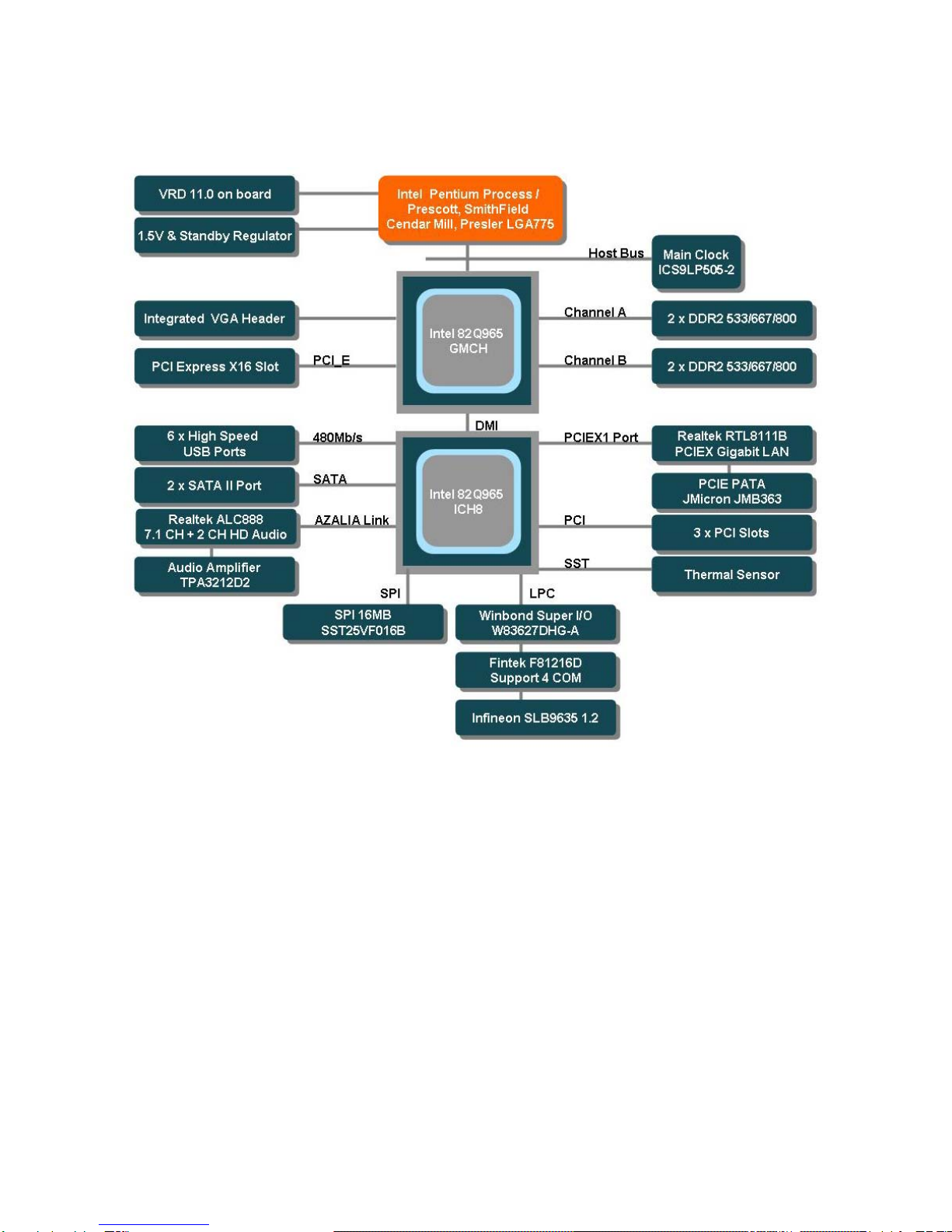
12
Block Diagram

User’s Manual
MX965Q2
13
This chapter describes the main board
features and the new technologies
it supports.
1
Product
introduction
1
Product
introduction
MX965Q2
14
Production Introduction
1.1 Before you Proceed
Take note of the following precautions before you install motherboard components or
change any motherboard settings.
zUnplug the power cord from the wall socket before touching any
component.
zUse a grounded wrist strap or touch a safely grounded object or a
metal object, such as the power supply case, before handling
components to avoid damaging them due to static electricity
zHold components by the edges to avoid touching the ICs on
them.
zWhenever you uninstall any component, place it on a grounded
antistatic pad or in the bag that came with the component.
zBefore you install or remove any component, ensure that the ATX
power supply is switched off or the power cord is detached from
the power supply. Failure to do so may cause severe damage to
the motherboard, peripherals, and/or components.
User’s Manual
MX965Q2
15
1.2 Motherboard Overview
Before you install the motherboard, study the configuration of your chassis to ensure that
the motherboard fits into it. Refer to the chassis documentation before installing the
motherboard.
Make sure to unplug the power cord before installing or removing the
motherboard. Failure to do so can cause you physical injury and
damage motherboard components.
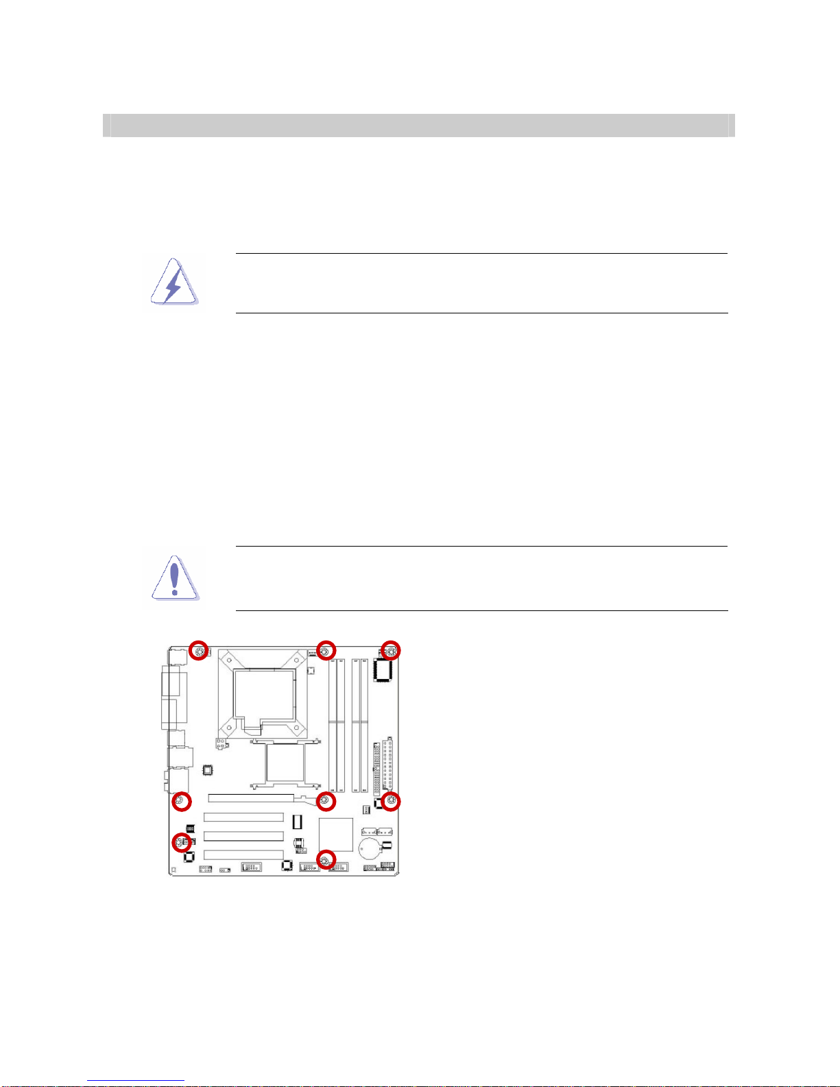
1.2.1 Placement Direction
When installing the motherboard, make sure that you place it into the chassis in the correct
orientation. The edge with external ports goes to the rear part of the chassis as indicated in
the image below.
1.2.2 Screw Holes
Place eight (8) screws into the holes indicated by circles to secure the motherboard to the
chassis.
Do not over tighten the screws! Doing so can damage the
motherboard.
Place this side towards the rear of the
chassis
MX965Q2
16
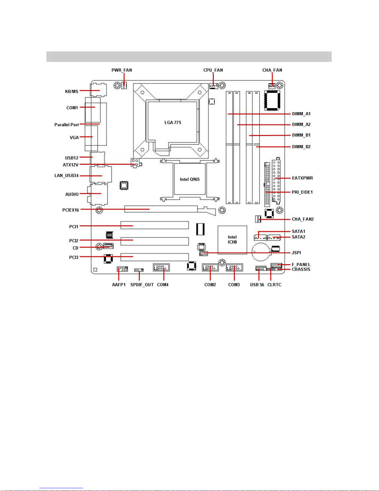
1.3 Motherboard Layout
User’s Manual
MX965Q2
17
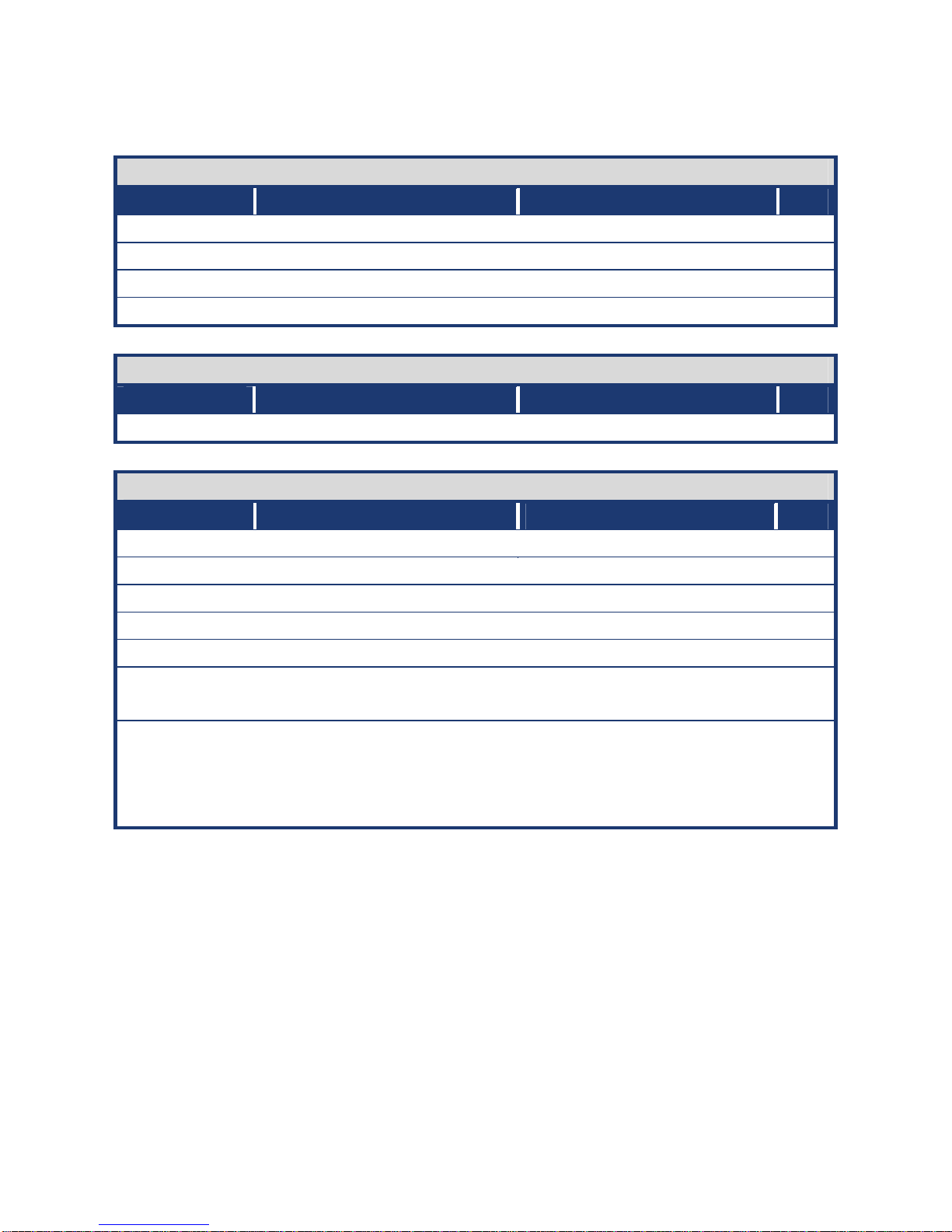
1.3.1 Layout Content List
Slots
Label Function Note Page
DIMM_A1, A2 240-pin DDR2 DIMM slot N/A
DIMM_B1, B2 240-pin DDR2 DIMM slot N/A
PCIEX16 PCI Express X16 Slot N/A
PCI1, 2, 3 PCI Slot N/A
Jumpers
Label Function Note Page
CLRTC Clear CMOS 3 x 1 header, pitch 2.54mm 32
Rear Panel Connector
Label Function Note Page
KBMS PS/2 keyboard and mouse 6-pin Mini-Din 33,35
LPT Parallel port connector D-sub 25-pin, female 33
COM1 Serial port connector D-sub 9-pin, male 35
VGA VGA connector D-sub 15-pin, female 35
USB12 USB connector x 2 35
LAN_USB34 RJ-45 Ethernet connector x 1
USB connector x 2 33,34
AUDIO Rear speaker out port,
Center/Subwoofer port, Line-in
port, Line-out port, Microphone
port, Side speaker out port
7.1 Channel Audio I/O (6 jacks) 33,34

MX965Q2
18
Internal Connector
Label Function Note Page
AAFP1 Front Panel Audio Connector 5 x 2 header, pitch 2.54mm 36
ATX12V ATX Power Connector 2 x 2 header 37
CD Optical Drive Audio Connector 4 x 1 header, pitch 2.54mm 38
COM2 Serial Port 2 Connector 5 x 2 box header, pitch 2.54mm 38
COM3 Serial Port 3 Connector 5 x 2 box header, pitch 2.54mm 39
COM4 Serial Port 4 Connector 5 x 2 box header, pitch 2.54mm 39
CHASSIS Chassis Intrusion Connector 4 x 1 header, pitch 2.54mm 40
CHA_FAN Chassis Fan Connector 3 x 1 wafer, pitch 2.54mm 40
CHA_FAN2 Chassis Fan Connector 3 x 1 wafer, pitch 2.54mm 41
CPU_FAN CPU Fan Connector 3 x 1 wafer, pitch 2.54mm 41
EATXPWR ATX Power Connector 12 x 2 header 37
F_PANEL System Panel Connector 5 x 2 header, pitch 2.54mm 42
JSPI SPI Connector 4 x 2 header, pitch 2.54mm 43
PRI_EIDE1 Primary IDE Connector 20 x 2 header, pitch 2.54mm 43
PWR_FAN Power Fan Connector 3 x 1 wafer, pitch 2.54mm 44
SATA1 Serial ATA Connectors [Red] 7-pin header 44
SATA2 Serial ATA Connectors [Red] 7-pin header 44
SPDIF_OUT1 Digital Audio Connector 4 x 1 header, pitch 2.54mm 45
USB56 USB 2.0 Connector 5 x 2 header, pitch 2.54mm 46

User’s Manual
MX965Q2
19
1.4 Central Processing Unit (CPU)
The motherboard comes with a surface mount LGA775 socket designed for the Intel®
LGA775 Core 2 Extreme / Core 2 Quad / Core 2 Duo / Core Duo / Pentium 4 / Celeron D
CPU processors.
zMake sure the AC power is off before you install the CPU.
zIf installing a dual-core CPU, connect the CPU fan cable to the
CPU_FAN connector to ensure system stability.
zYour boxed Intel® Core 2 Extreme / Core 2 Quad / Core 2 Duo /
Core Duo / Pentium 4 / Celeron D CPU processors package
should come with installation instructions for the CPU, heatsink,
and the retention mechanism. If the instructions in this section do
not match the CPU documentation, follow the latter.
zUpon purchase of the motherboard, make sure that the PnP cap
is on the socket and the socket contacts are not bent. Contact
your retailer immediately if the PnP cap is missing, or if you see
any damage to the PnP cap/socket contacts/motherboard
components. Your place of purchase or local distributor will
shoulder the cost of repair only if the damage is
shipment/transit-related.
zKeep the cap after installing the motherboard. Your place of
purchase or local distributor will process Return Merchandise
Authorization (RMA) requests only if the motherboard comes with
the cap on the LGA775 socket.
zThe product warranty does not cover damage to the socket
contacts resulting from incorrect CPU installation/removal, or
misplacement/loss/ incorrect removal of the PnP cap..

MX965Q2
20
1.4.1 Installing the CPU
1. Locate the CPU socket on the
motherboard.
Before installing the CPU,
make sure that the socket
box is facing towards you and
the load lever is on your left.
2. Press the load lever with your thumb (A), then move it to the left (B) until it is released
from the retention tab.
To prevent damage to the socket pins, do not remove the PnP cap
unless you are installing a CPU.
3. Lift the load lever in the direction of the
arrow to a 135º angle.
This manual suits for next models
1
Table of contents
Other Advansus Motherboard manuals

Advansus
Advansus i915GV2-LEI User manual

Advansus
Advansus i965GM-DCQI User manual

Advansus
Advansus i945GM3-DCQI User manual

Advansus
Advansus TC2220-CX700M User manual

Advansus
Advansus DS3630-945GSE User manual

Advansus
Advansus VCN700-LIC10 User manual

Advansus
Advansus iQ965-IGM User manual

Advansus
Advansus iQ96503-IQGM Installation and operation manual

Advansus
Advansus iQ96503 User manual

Advansus
Advansus LM5560-Q45 User manual


