ECS 945GCT-M2 User manual

Preface
i
Preface
Copyright
This publication, including all photographs, illustrations and software, is protected under
international copyright laws, with all rights reserved. Neither this manual, nor any of the
material contained herein, may be reproduced without written consent of the author.
Version 1.0
Disclaimer
The information in this document is subject to change without notice. The manufacturer
makes no representations or warranties with respect to the contents hereof and specifically
disclaims any implied warranties of merchantability or fitness for any particular purpose.
The manufacturer reserves the right to revise this publication and to make changes from
time to time in the content hereof without obligation of the manufacturer to notify any
person of such revision or changes.
TrademarkRecognition
Microsoft, MS-DOS and Windows are registered trademarks of Microsoft Corp.
MMX, Pentium, Pentium-II, Pentium-III, Celeron are registered trademarks of Intel Cor-
poration.
Other product names used in this manual are the properties of their respective owners and
are acknowledged.
FederalCommunicationsCommission(FCC)
This equipment has been tested and found to comply with the limits for a Class B digital
device, pursuant to Part 15 of the FCC Rules. These limits are designed to provide reason-
able protection against harmful interference in a residential installation. This equipment
generates, uses, and can radiate radio frequency energy and, if not installed and used in
accordance with the instructions, may cause harmful interference to radio communications.
However, there is no guarantee that interference will not occur in a particular installation.
If this equipment does cause harmful interference to radio or television reception, which
can be determined by turning the equipment off and on, the user is encouraged to try to
correct the interference by one or more of the following measures:
• Reorient or relocate the receiving antenna
• Increase the separation between the equipment and the receiver
• Connect the equipment onto an outlet on a circuit different from that to which
the receiver is connected
• Consult the dealer or an experienced radio/TV technician for help
Shielded interconnect cables and a shielded AC power cable must be employed with this
equipment to ensure compliance with the pertinent RF emission limits governing this
device. Changes or modifications not expressly approved by the system’s manufacturer
could void the user’s authority to operate the equipment.

ii
Preface
DeclarationofConformity
This device complies with part 15 of the FCC rules. Operation is subject to the following
conditions:
• This device may not cause harmful interference, and
• This device must accept any interference received, including interference
that may cause undesired operation
CanadianDepartmentofCommunications
This class B digital apparatus meets all requirements of the Canadian Interference-causing
Equipment Regulations.
Cet appareil numérique de la classe B respecte toutes les exigences du Réglement sur le
matériel brouilieur du Canada.
AbouttheManual
The manual consists of the following:
Chapter 1
Introducing the Motherboard
Chapter 2
Installing the Motherboard
Chapter 3
UsingBIOS
Chapter 4
Using the Motherboard Software
Describes features of the motherboard.
Go to Hpage 1
Describes installation of motherboard
components.
Goto Hpage 7
Provides information on using the BIOS
Setup Utility.
Go to Hpage 27
Describes the motherboard software
Go to Hpage 41

iii
TT
TT
TABLE OF CONTENTSABLE OF CONTENTS
ABLE OF CONTENTSABLE OF CONTENTS
ABLE OF CONTENTS
Preface i
Chapter 1
1
IntroducingtheMotherboard 1
Introduction.................................................................................................1
Feature..........................................................................................................2
MotherboardComponents........................................................................4
Chapter 2 77
77
7
Installing the Motherboard 7
SafetyPrecautions......................................................................................7
Choosinga ComputerCase.......................................................................7
Installingthe Motherboard ina Case......................................................7
CheckingJumperSettings.........................................................................8
Setting Jumpers..............................................................................8
Checking Jumper Settings..............................................................9
Jumper Settings..............................................................................9
InstallingHardware..................................................................................10
Installing the Processor................................................................10
Installing Memory Modules.........................................................12
Expansion Slots............................................................................15
Connecting Optional Devices.......................................................17
Installing a Hard Disk Drive/CD-ROM/SATA Hard Drive........20
Installing a Floppy Diskette Drive...............................................21
ConnectingI/ODevices..........................................................................22
ConnectingCase Components...............................................................23
Front Panel Header......................................................................25
Chapter 3 27
UsingBIOS 27
Aboutthe SetupUtility...........................................................................27
The Standard Configuration........................................................27
Entering the Setup Utility..............................................................27
UsingBIOS................................................................................................28
Standard CMOS Setup.................................................................29
Advanced Setup............................................................................30
Advanced Chipset Setup...............................................................32

iv
Integrated Peripherals.................................................................33
Power Management Setup...........................................................34
PCI/PnP Setup.............................................................................35
PC Health Status..........................................................................36
Frequency/Voltage Control..........................................................37
Load Optimal Defaults................................................................38
Supervisor Password..................................................................38
User Password............................................................................39
Save & Exit Setup.........................................................................39
Exit Without Saving......................................................................39
Updating the BIOS.......................................................................40
Chapter 4 4141
4141
41
UsingtheMotherboardSoftware 41
AbouttheSoftwareCD-ROM................................................................41
Auto-installingunderWindows 2000/XP.............................................41
Running Setup..............................................................................42
ManualInstallation..................................................................................44
UtilitySoftwareReference......................................................................44

1
IntroducingtheMotherboard
Chapter1
IntroducingtheMotherboard
Introduction
Thank you for choosing the 945GCT-M2 motherboard. This motherboard is a high perfor-
mance, enhanced function motherboard designed to support the LGA775 socket Intel
CoreTM 2 Duo/*Pentium D/*Pentium 4/Celeron D processors for high-end business or per-
sonal desktop markets.
The motherboard incorporates the 945GC Northbridge (NB) and ICH7 Southbridge (SB)
chipsets. The Northbridge supports a Front Side Bus (FSB) frequency of 1066/800/533 MHz
using a scalable FSB Vcc_CPU. The memory controller supports DDR2 memory DIMM
frequencies of 667/533/400. It supports two DDR2 Sockets with up to maximum memory
of 2 GB DDR2 Maximum memory bandwidth of 8.5 Gb/s in dual-channel interleaved mode
assuming DDR2 667 MHz. High resolution graphics via one PCI Express slot, intended for
Graphics Interface, is fully compliant to the PCI Express Base Specification revision 1.0a.
The ICH7 Southbridge supports two PCI slots which are PCI 2.3 compliant. It implements
an EHCI compliant interface that provides 480 Mb/s bandwidth for eight USB 2.0 ports.
One onboard IDE connector supports 2 IDE devices in Ultra ATA 100/66/33 mode. The
Southbridge integrates a Serial ATA host controller, supporting four SATA ports with maxi-
mum transfer rate up to 3.0 Gb/s each.
The motherboard is equipped with advanced full set of I/O ports in the rear panel, including
PS/2 mouse and keyboard connectors, COM1, one VGA port, four USB ports, one LAN port
and audio jacks for microphone, line-in and line-out.
“*” stands for this motherboard is ready to support Pentium D/ Pentium 4 proces-
sors.

2
IntroducingtheMotherboard
Feature
• Accommodates Intel CoreTM 2 Duo/*Pentium D/*Pentium 4/Celeron D proces-
sors
• Supports a system bus (FSB) of 1066/800/533 MHz
• Supports “Hyper-Threading” technology CPU
The motherboard uses an LGA775 type of Intel CoreTM 2 Duo/*Pentium D/*Pentium 4/
Celeron D that carries the following features:
Processor
“Hyper-Threading” technology enables the operating system into thinking it’s hooked
up to two processors, allowing two threads to be run in parallel, both on separate
“logical” processors within the same physical processor.
* Supports 05A, 06 FMB CPU
The 945GC Northbridge (NB) and ICH7 Southbridge (SB) chipsets are based on an
innovative and scalable architecture with proven reliability and performance.
Chipset
ICH7 (SB) • EnhancedDMAController,interruptcontroller,andtimerfunc-
tions
• Compliant with PCI Express Base Specification, Revision
1.0a
• Compliant with PCI 2.3 specification
• Integrated SATA 3.0 Gb/s Host Controller
• Integrated USB 2.0 Host Controller supporting up to eight
USB 2.0 ports
• Integrated IDE controller supports Ultra ATA 100/66/33
• Supports DDR2 667/533/400 DDR SDRAM with Dual-channel architecture
• Accommodates two unbuffered DIMMs
• Up to 1 GB per DIMM with maximum memory size up to 2 GB
Memory
945GC (NB) • Supports 32-bit host bus addressing, allowing the CPU to
access the entire 2 GB of the memory address space.
• 2GB/s point-to-point Direct MediaInterface (DMI) toICH7 (1
GB/s)each direction.
• Supports 256-Mb, 512-Mb and 1-Gb DDR2 technologies for
x8 and x16 devices
• Supports high quality 3D setup, Render Engine and high-
quality texture engine
Audio
• 5.1 Channel High DefinitionAudio Codec
• All DACs support 192K/96K/48K/44.1KHz sample rate
• Software selectable 2.5V/3.75V VREFOUT
• Meets Microsoft WHQL/WLP 2.x audio requirements
• Direct Sound 3DTM compatible
* This motherboard is ready to support Pentium D/ Pentium 4 processors

3
IntroducingtheMotherboard
The motherboard comes with the following expansion options:
Onboard LAN (Optional)
• One PCI Express Slot for Graphic Interface
• Two 32-bit PCI v2.3 compliant slots
• One 40-pin IDE connector that support two IDE devices
• One floppy disk drive interface
• Four 7-pin SATA connectors
Expansion Options
The motherboard supports UDMA bus mastering with transfer rates of 100/66/33 Mb/
s.
• Integrated 10/100/1000 transceiver
• Supports PCI v2.3, 32-bit, 33/66 MHz
•Supports Wake-On-LAN (WOL) function and remote wake-up
The onboard LAN controller provides the following features:
• Two PS/2 ports for mouse and keyboard
• One serial port
• One VGA port
• Four USB ports
• One LAN port
• Audio jacks for microphone, line-in and line-out
The motherboard has a full set of I/O ports and connectors:
Integrated I/O
The firmware can also be used to set parameters for different processor clock speeds.
• Power management
• Wake-up alarms
• CPUparameters
• CPUandmemorytiming
BIOS Firmware
This motherboard uses AMI BIOS that enables users to configure many system
features including the following:
1. Some hardware specifications and software items are subject to change
without prior notice.
2. Due to chipset limitation, we recommend that motherboard be operated in
the ambiance between 0 and 50 °C.
• Supports 10/100 Mb/s N-Way Auto negotiation operation
• Half/Full duplex capacity
• Supports Wake-On-LAN (WOL) function and remote wake-up
4
IntroducingtheMotherboard
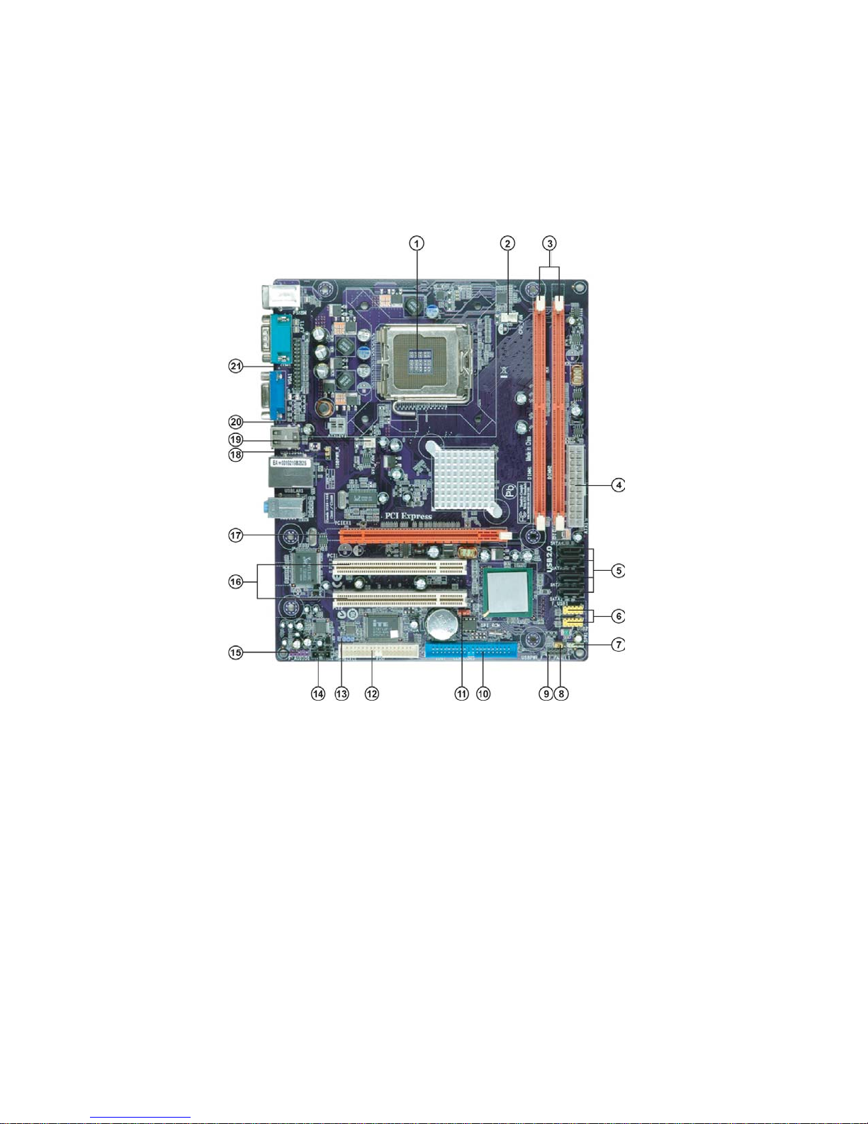
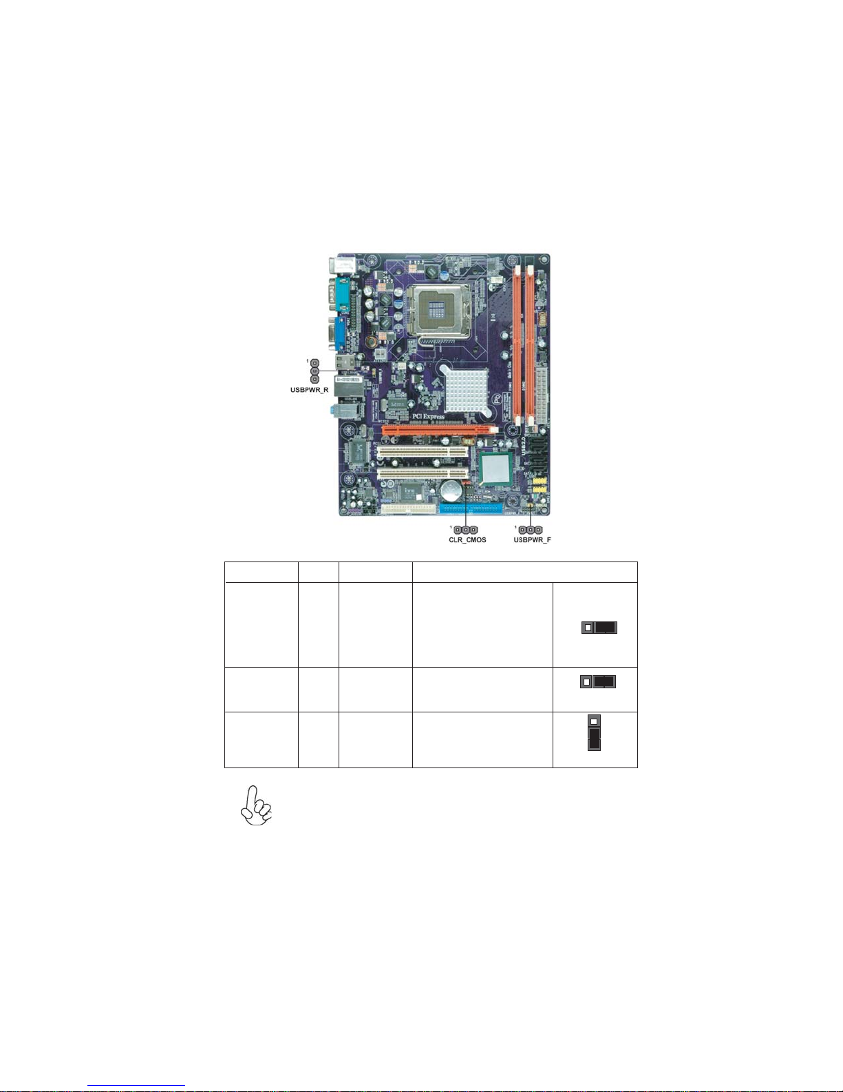
MotherboardComponents

5
IntroducingtheMotherboard
Table of Motherboard Components
This concludes Chapter 1. The next chapter explains how to install the motherboard.
LABEL COMPONENTS
1. CPU Socket LGA775 Socket for Intel®Core™ 2 Duo/*Pentium®
D/*Pentium®4/ Celeron®D CPUs
2. CPU_FAN CPU cooling fan connector
3. DIMM1/2 240-
p
in DDR2 SDRAM slots
4. ATX1 Standard 24-Pin ATX Power connector
5. SATA1~4 Serial ATA connectors
6. F_USB1~2 Front Panel USB headers
7. SPK1 Speaker header
8. USBPWR_F Front Panel USB Power Select Jumper
9. F_PANEL1 Front panel switch/LED header
10. IDE1 Primary IDE connector
11. CLR_CMOS Clear CMOS jumper
12. FDD Floppy Disk Drive connector
13. SPDIFO1 SPDIF out header
14. CD_IN1 Analog audio input connecor
15. F_AUDIO1 Front Panel Audio header
16. PCI1~2 32-bit add-on card slots
17. PCIEX16 PCI Express slot for graphics interface
18. USBPWR_R Rear Panel USB PS/2 Power Select Jumper
19. SYS_FAN System Fan connector
20. ATX12V1 4-pin +12V power connector
21. LPT1 Parallel port header
“*” stands for this motherboard is ready to support Pentium D/Pentium 4 processors.

6
IntroducingtheMotherboard
Memo

7
InstallingtheMotherboard
Chapter2
InstallingtheMotherboard
SafetyPrecautions
• Follow these safety precautions when installing the motherboard
• Wear a grounding strap attached to a grounded device to avoid damage from
static electricity
• Discharge static electricity by touching the metal case of a safely grounded
object before working on the motherboard
• Leave components in the static-proof bags they came in
• Hold all circuit boards by the edges. Do not bend circuit boards
ChoosingaComputerCase
There are many types of computer cases on the market. The motherboard complies with
the specifications for the Micro ATX system case. First, some features on the motherboard
are implemented by cabling connectors on the motherboard to indicators and switches on
the system case. Make sure that your case supports all the features required. Secondly, this
motherboard supports one floppy diskette drive and two enhanced IDE drives. Make sure
that your case has sufficient power and space for all drives that you intend to install.
Most cases have a choice of I/O templates in the rear panel. Make sure that the I/O template
in the case matches the I/O ports installed on the rear edge of the motherboard.
This motherboard carries a Micro ATX form factor of 244 x 210 mm. Choose a case that
accommodates this form factor.
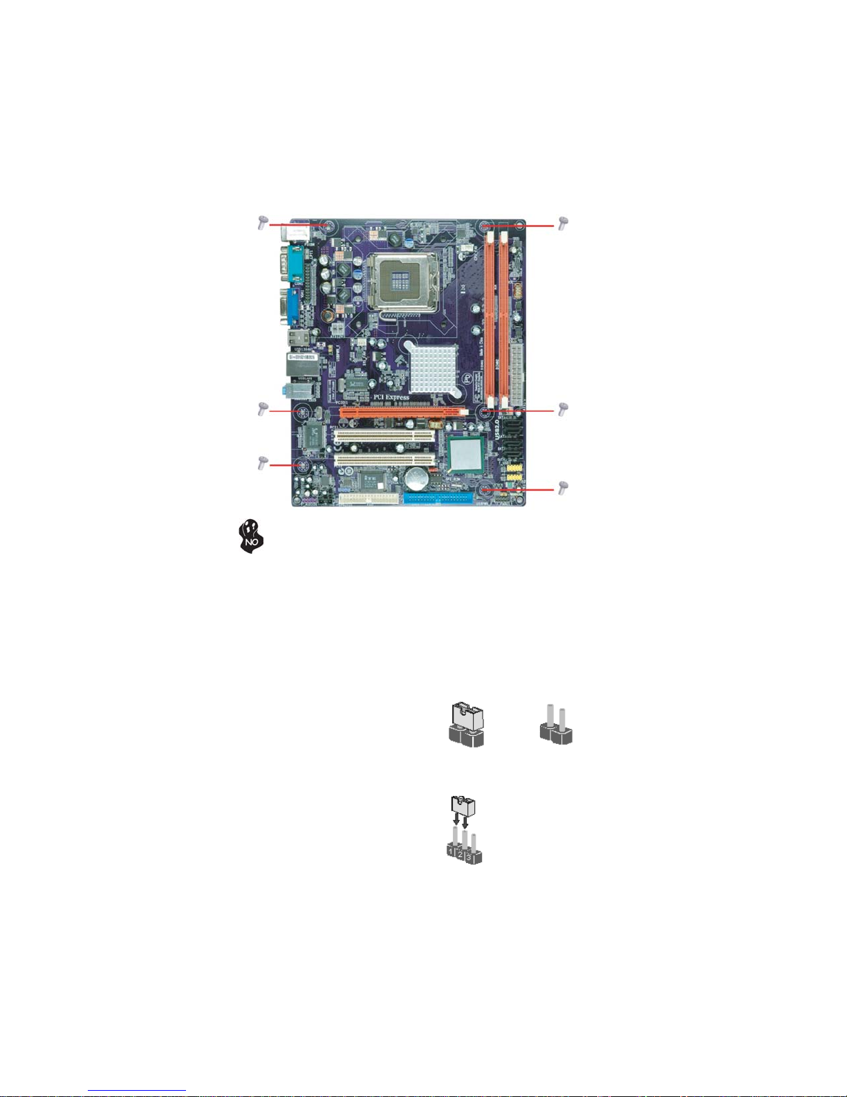
InstallingtheMotherboardinaCase
Refer to the following illustration and instructions for installing the motherboard in a case.
Most system cases have mounting brackets installed in the case, which correspond the holes
in the motherboard. Place the motherboard over the mounting brackets and secure the
motherboard onto the mounting brackets with screws.
Ensure that your case has an I/O template that supports the I/O ports and expansion slots
on your motherboard.
8
InstallingtheMotherboard
CheckingJumperSettings
This section explains how to set jumpers for correct configuration of the motherboard.
SettingJumpers
Use the motherboard jumpers to set system configuration options. Jumpers with more than
one pin are numbered. When setting the jumpers, ensure that the jumper caps are placed on
the correct pins.
The illustrations show a 2-pin jumper. When
the jumper cap is placed on both pins, the
jumper is SHORT. If you remove the jumper
cap, or place the jumper cap on just one pin,
the jumper is OPEN.
This illustration shows a 3-pin jumper. Pins
1 and 2 are SHORT.
SHORT OPEN
Do not over-tighten the screws as this can stress the motherboard.
9
InstallingtheMotherboard
Checking Jumper Settings
The following illustration shows the location of the motherboard jumpers. Pin 1 is labeled.
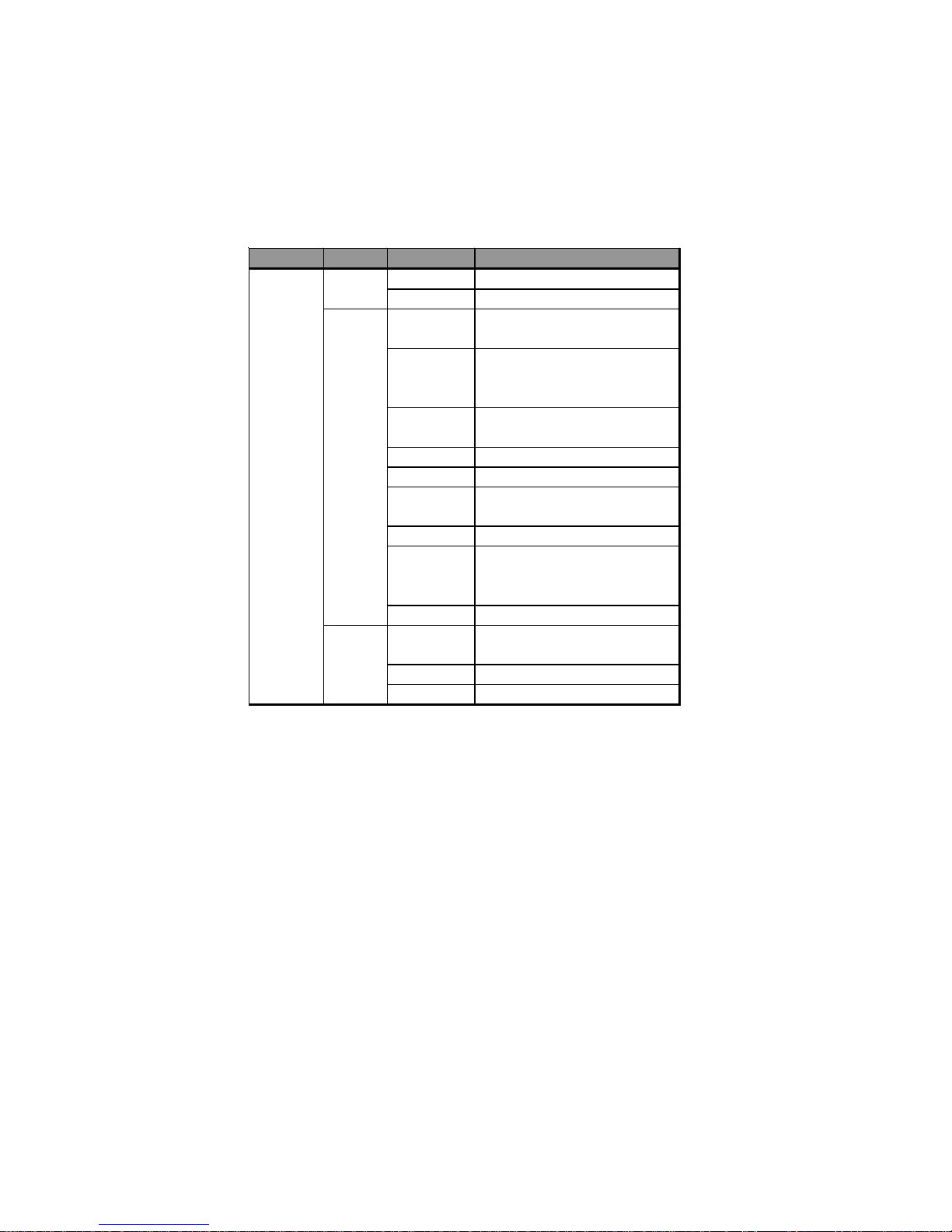
JumperSettings
USBPWR_F
USBPWR_R
Jumper Type Description Setting (default)
CLR_CMOS 3-pin Clear CMOS
1-2: NORMAL
2-3: CLEAR CMOS
Before clearing the
CMOS, make sure to
turn off the system.
1
CLR_CMOS
USBPWR_F 3-pin USB Power 2-3: 5VSB
USBPWR_R 3-pin 1-2: VCC
1
Front Panel 1-2: VCC
Select Jumper
1
Rear USB PS/2
Power Select
Jumper 2-3: 5VSB
1. To avoid the system unstability after clearing CMOS, we recommend users
to enter the main BIOS setting page to “Load Optimal Defaults” and then
“Save Changes and Exit”.
2. Make sure the power supply provides enough 5VSB voltage before select-
ing the 5VSB function.
3. It is required that users place the USBPWR_F & USBPWR_R cap onto 2-
3 pin rather than 1-2 pin as default if you want to wake up the computer by
USB/PS2 KB/Mouse.

10
InstallingtheMotherboard
InstallingHardware
Installing the Processor
Caution: When installing a CPU heatsink and cooling fan make sure that
you DO NOT scratch the motherboard or any of the surface-mount resistors
with the clip of the cooling fan. If the clip of the cooling fan scrapes across
the motherboard, you may cause serious damage to the motherboard or its
components.
On most motherboards, there are small surface-mount resistors near the
processor socket, which may be damaged if the cooling fan is carelessly
installed.
Avoid using cooling fans with sharp edges on the fan casing and the clips.
Also, install the cooling fan in a well-lit work area so that you can clearly see
the motherboard and processor socket.
This motherboard has a LGA775 socket. When choosing a processor, consider the perfor-
mance requirements of the system. Performance is based on the processor design, the clock
speed and system bus frequency of the processor, and the quantity of internal cache memory
and external cache memory.
This motherboard automatically determines the CPU clock frequency and system bus
frequency for the processor. You may be able to change the settings in the system Setup
Utility. We strongly recommend that you do not over-clock processors or other compo-
nents to run faster than their rated speed.
Before installing the Processor
Fail-Safe Procedures for Over-clocking
When end-users encounter failure after attempting over-clocking, please take the follow-
ing steps to recover from it.
1. Shut down the computer.
2. Press and hold the “Page Up Key (PgUp)” of the keyboard, and then boot the PC up.
3. Two seconds after the PC boots up, release the “Page Up Key (PgUp)”.
4. The BIOS returns to the default setting by itself.
Warning:
1. Over-clocking components can adversely affect the reliability of the sys-
tem and introduce errors into your system. Over-clocking can permanently
damage the motherboard by generating excess heat in components that are
run beyond the rated limits.
2. Always remove the AC power by unplugging the power cord from the
power outlet before installing or removing the motherboard or other hard-
ware components.
11
InstallingtheMotherboard
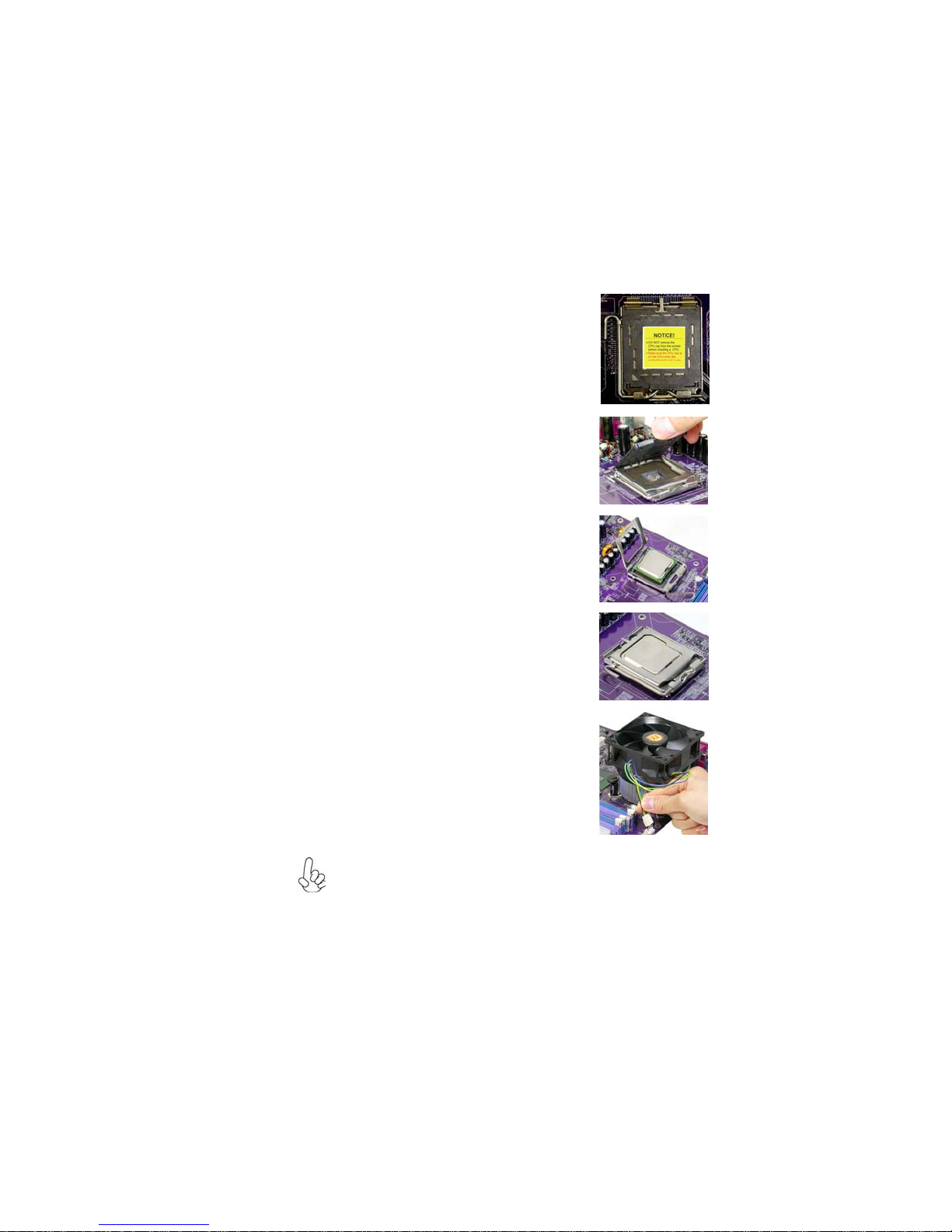
A. Read and follow the instructions shown on the
sticker on the CPU cap.
B. Unload the cap
· Use thumb & forefinger to hold the
lifting tab of the cap.
· Lift the cap up and remove the cap
completely from the socket.
C. Open the load plate
· Use thumb & forefinger to hold the
hook of the lever, pushing down and pulling
aside unlock it.
· Lift up the lever.
· Use thumb to open the load plate. Be
careful not to touch the contacts.
D. Install the CPU on the socket
· Orientate CPU package to the socket.
Make sure you match triangle marker
to pin 1 location.
E. Close the load plate
· Slightly push down the load plate onto the
tongue side, and hook the lever.
· CPUis locked completely.
F. Apply thermal grease on top of the CPU.
G. Fasten the cooling fan supporting base onto
the CPU socket on the motherboard.
H. Make sure the CPU fan is plugged to the
CPU fan connector. Please refer to the CPU
cooling fan user’s manual for more detail
installation procedure.
CPU Installation Procedure
The following illustration shows CPU installation components.
1. To achieve better airflow rates and heat dissipation, we suggest that you
use a high quality fan with 3800 rpm at least. CPU fan and heatsink
installation procedures may vary with the type of CPU fan/heatsink sup
plied. The form and size of fan/heatsink may also vary.
2. DO NOT remove the CPU cap from the socket before installing a CPU.
3. Return Material Authorization (RMA) requests will be accepted only if
the motherboard comes with the cap on the LGA775 socket.

12
InstallingtheMotherboard
Installing Memory Modules
This motherboard accommodates two memory modules. It can support two 240-pin DDR2
667/533/400. The total memory capacity is 2 GB.
You must install at least one module in any of the two slots. Each module can be installed
with 256 MB to 1 GB of memory; total memory capacity is 2 GB.
Do not remove any memory module from its antistatic packaging until you
are ready to install it on the motherboard. Handle the modules only by
their edges. Do not touch the components or metal parts. Always wear a
grounding strap when you handle the modules.
Installation Procedure
Refer to the following to install the memory modules.
1 This motherboard supports unbuffered DDR2 SDRAM .
2 Push the latches on each side of the DIMM slot down.
3 Align the memory module with the slot. The DIMM slots are keyed with notches
and the DIMMs are keyed with cutouts so that they can only be installed
correctly.
4 Checkthat the cutouts on the DIMM moduleedge connector matchthe notches
inthe DIMM slot.
5 Install the DIMM module into the slot and press it firmly down until it seats
correctly. The slot latches are levered upwards and latch on to the edges of
theDIMM.
6 Installany remaining DIMM modules.
DDR2 SDRAM memory module table
DDR2 533 266 MHz
DDR2 400 200 MHz
DDR2 667 333 MHz
Memory module Memory Bus

13
InstallingtheMotherboard
Table A: DDR2(memory module) QVL (Qualified Vendor List)
The following DDR2 667/533/400 memory modules have been tested and qualified for use
with this motherboard.
Type Size Vendor Module Name
HYMP532U646-E3 AA
DDRII 400 NT256T64UH4A0F-5A
512 MB Nanya NT512T64U88A0F-5A
A-DATA M2OHY2F3G3110A1B0Z
Elixir M2U25664TUH4A0F-37B
Infineon HYS64T32400HU-3.7-A
256 MB ELPIDA E5116AF-5C-E
HYB18T512160AC-3.7
Ramaxel RML 1040M28D5F-533
Samsung M378T3253FGO-CD5
AET660UD00-370A98U
Aeneon AET660UD00-370A98X
AET660UD00-370A98Z
Infineon HYS64T64400HU-3.7-A
Kingston ELPIDA E5108AB-5C-E
HYB18T512800AF37
PQI MEABR321LA01AA
Samsung M378T6553BGO-CD5
Apacer ELPIDA E5108AB-5C-E
Infineon HYS64T128920HU-3.7-A
1 GB Kingston NANYA NT5TU64M8AE-37B
PQI MEABR421LA0106
UMAX UMAX U2S12D30TP-5C
DDRII 533
256 MB Hynix
Kingston
512 MB
14
InstallingtheMotherboard
Type Size Vendor Module Name
Infineon HYS64T325001HU-3-A
Ramxel 5NB31 D9DCG
AD29608A88-3EG
Eipida M20EL5G3H3160B100Z
Corsair K4T5108QC
Corsair VALUESELECT 32M8CEC
64M8CFEPS1000545
GL2L64M088BA18W
GL2L64M088BA30AW
Infinity 0547W64M8 PC5300
Ramxel 5LB31 D9DCL
K4T51083QC
PC35300U-25331-Z
Sync MAX 04400WB01 R050008A
JetRam J12Q3AB-6
Transcend SEL520ZCE6 K4T51083QC
TAIWAN-G6E
Twinmos TMM6208G8M30B
AM4B5708GQJS7E0631F
Elpida AM4B5708GQJS7E0631
Infineon HYB18T512800BF3S
PQI PQB2648D38R0648
DDRII 667
256 MB
512 MB
A-DATA
GEIL
Samsung
Apacer
1 GB
Table of contents
Other ECS Motherboard manuals


