ECS P55H-AK User manual

Preface
Preface
Copyright
This publication, including all photographs, illustrations and software, is protected
under international copyright laws, with all rights reserved. Neither this manual, nor
any of the material contained herein, may be reproduced without written consent of
the author.
Version 1.0
Disclaimer
The information in this document is subject to change without notice. The manufac-
turer makes no representations or warranties with respect to the contents hereof and
specifically disclaims any implied warranties of merchantability or fitness for any
particular purpose. The manufacturer reserves the right to revise this publication and
to make changes from time to time in the content hereof without obligation of the
manufacturer to notify any person of such revision or changes.
TrademarkRecognition
Microsoft, MS-DOS and Windows are registered trademarks of Microsoft Corp.
MMX, Pentium, Pentium-II, Pentium-III, Celeron are registered trademarks of Intel
Corporation.
Other product names used in this manual are the properties of their respective
owners and are acknowledged.
FederalCommunicationsCommission(FCC)
This equipment has been tested and found to comply with the limits for a Class B
digital device, pursuant to Part 15 of the FCC Rules. These limits are designed to
provide reasonable protection against harmful interference in a residential installa-
tion. This equipment generates, uses, and can radiate radio frequency energy and, if
not installed and used in accordance with the instructions, may cause harmful inter-
ference to radio communications. However, there is no guarantee that interference
will not occur in a particular installation. If this equipment does cause harmful
interference to radio or television reception, which can be determined by turning the
equipment off and on, the user is encouraged to try to correct the interference by one
or more of the following measures:
• Reorient or relocate the receiving antenna
• Increase the separation between the equipment and the receiver
• Connect the equipment onto an outlet on a circuit different from that to
which the receiver is connected
• Consult the dealer or an experienced radio/TV technician for help
Shielded interconnect cables and a shielded AC power cable must be employed with
this equipment to ensure compliance with the pertinent RF emission limits governing
this device. Changes or modifications not expressly approved by the system’s manu-
facturer could void the user’s authority to operate the equipment.

ii
Preface
DeclarationofConformity
This device complies with part 15 of the FCC rules. Operation is subject to the
following conditions:
• This device may not cause harmful interference, and
• This device must accept any interference received, including interfer-
ence that may cause undesired operation
CanadianDepartmentofCommunications
This class B digital apparatus meets all requirements of the Canadian Interference-
causing Equipment Regulations.
Cet appareil numérique de la classe B respecte toutes les exigences du Réglement sur
le matériel brouilieur du Canada.
AbouttheManual
The manual consists of the following: Describes features of the
motherboard
Go to Hpage 1
Describes installation of
motherboard components
Goto H
Provides information on using
the BIOS Setup Utility
Go to Hpage 29
Goto H
Describes the ATI CrossfireTM
Technology
page 53
Describesthe motherboard soft-
ware
Go to Hpage 57
Chapter 2
Chapter 1
Introducing the Motherboard
Chapter 3
Using BIOS
Chapter 4
Using the Motherboard Software
Chapter 5
ATI CrossfireTM Technology Support
Describes the Intel®®
®®
®Matrix Stor-
age Manager RAID Configura-
tions
Chapter 7
Intel®®
®®
®Matrix Storage Manager RAID
Configurations Go to Hpage 65
Chapter 8
Marvell 88SE9128 SATA 6Gb/s RAID
Controller BIOS Setup
Describes the SATA RAID
Setup
Go to Hpage 71
page 7
Installing the Motherboard
Chapter 9 Provides basic trouble shooting
Chapter 6
NVIDIA®®
®®
®Hybrid SLI®®
®®
®Technology Support
ProvidesinformationaboutSATA
RAIDSetup
Go to Hpage 61
Trouble Shooting tips
Hpage 77
Go to

iii
Chapter 2 77
77
7
Installing the Motherboard 7
SafetyPrecautions...........................................................................7
Choosinga ComputerCase............................................................7
Installingthe Motherboard in a Case...........................................7
CheckingJumperSettings..............................................................8
Setting Jumpers.......................................................................8
Checking Jumper Settings.......................................................9
Jumper Settings.......................................................................9
InstallingHardware...................................................................10
Installing the Processor.........................................................10
Installing Memory Modules...................................................12
Expansion Slots......................................................................16
Connecting Optional Devices.................................................18
Installation of Front USB 3.0 Panel.......................................21
Installing SATA Hard Drives..................................................23
ConnectingI/ODevices.................................................................24
ConnectingCase Components.....................................................25
Front Panel Header...............................................................28
TT
TT
TABLE OF CONTENTSABLE OF CONTENTS
ABLE OF CONTENTSABLE OF CONTENTS
ABLE OF CONTENTS
Preface i
Chapter 1 1
IntroducingtheMotherboard 1
Introduction....................................................................................1
Specifications....................................................................................2
MotherboardComponents............................................................5
Chapter 3 29
UsingBIOS 29
AbouttheSetupUtility.................................................................29
The Standard Configuration...................................................29
Entering the Setup Utility........................................................29
Resetting the Default CMOS Values.....................................30
UsingBIOS......................................................................................31
Standard CMOS Setup..........................................................32
Advanced Setup.....................................................................34
Advanced Chipset Setup.........................................................36

iv
Integrated Peripherals..........................................................37
Power Management Setup.....................................................38
PCI/PnP Setup.......................................................................39
PC Health Status...................................................................40
M.I.B. X(MB Intelligent BIOS X)...........................................44
Load Default Settings............................................................49
Load Profile Settings..............................................................49
Supervisor Password............................................................50
User Password......................................................................50
Save & Exit Setup...................................................................51
Exit Without Saving.................................................................51
Updating the BIOS..................................................................51
Chapter 4 5353
5353
53
UsingtheMotherboardSoftware 53
AbouttheSoftwareDVD-ROM/CD-ROM..................................53
Auto-installingunder WindowsXP/Vista/7...............................53
Running Setup..........................................................................54
ManualInstallation........................................................................56
UtilitySoftware Reference........................................................56
Chapter 5 5757
5757
57
ATICrossFireTM TechnologySupport 57
Requirements..................................................................................57
InstallingCrossFireTM graphicscards.........................................57
TheCatalystTM Control Center DialogBox.................................59
To Enable CrossFireTM..............................................................59
Chapter 7 6565
6565
65
Intel®MatrixStorageManagerRAIDConfigurations 65
Beforecreating aRAID set...........................................................65
Entering Intel®Matrix Storage Manager RAIDBIOSutility...66
CreatingaRAID set.......................................................................67
DeletingaRAID set.......................................................................69
Resettingdisks toNon-RAID......................................................70
ExitingSetup...................................................................................70
Chapter 6 6161
6161
61
NVIDIA®HybridSLI®TechnologySupport 61
Requirements..................................................................................61
Installingyour NVIDIA®SLI-Ready Components..................61
EnablingNVIDIA®SLI.................................................................63

v
Chapter 9 7777
7777
77
TroubleShooting 77
Startup problems duringassembly...................................................77
Startup problems after prolong use.................................................78
Maintenanceand care tips.................................................................78
Basic TroubleshootingFlowchart....................................................79
POSTCodeCheckpoints 8181
8181
81
Chapter 8 7171
7171
71
Marvell88SE9128SATA6Gb/sRAIDControllerBIOSSetup 71
ToCreateVirtualDisks.......................................................................71

vi
Memo

1
IntroducingtheMotherboard
Chapter1
IntroducingtheMotherboard
Introduction
Thank you for choosing P55H-AK motherboard. This motherboard is a high
performance, enhanced function motherboard designed to support the LGA1156
socket for Intel® Unlocked Core-i7 / Core-i5 processors to reach the optimum
system performance. Combined with ECS unique M.I.B X*BIOS interface, it
makes a simple, fast and safe O.C platform for high-end desktop and gaming
market.
P55H-AK is based on Intel P55 Express Chipset and NVIDIA nForce®200 PCI
Express switch chip to generate three of PCIe 16X Gen 2 graphic interface,
supporting 3-Way / 2-Way NVIDIA®SLITM and ATI CrossfireXTM technology
that allows you install up to three graphic cards with identical GPU running at PCIe
Gen 2 speed. It supports up to 16 GB of system memory with dual channel DDR3
2400 (OC) / 2200 (OC) / 2000 (OC) / 1800 (OC) / 1600 (OC) / 1333 / 1066
MHz memory modules. It provides one PCI rev 2.3 slot and two PCI Express x1
rev 2.0 slots for extending usage.
P55H-AK implements extra NEC UPD720200F1 USB3.0 and Marvell 88SE9128
SATA 6Gb/s chips, which provide four USB 3.0 ports (two USB 3.0 ports and one
USB 3.0 header for two frontal USB 3.0 ports), two SATA 6Gb/s and two eSATA
6Gb/s ports with RAID 0, 1 configuration, through PLX PEX 8608 PCIe Gen 2
switch, this motherboard delivers the highest data transfer rate to fulfill the most
speed-demanding usage.
The motherboard is equipped with advanced full set of I/O ports in the rear panel,
including one PS/2 mouse and keyboard combo connector, one CLR_CMOS
button,two eSATA 6Gb/s ports, two gigabit LAN ports, eight USB 2.0 ports, two
USB 3.0 ports running at 5Gb/s, one optical SPDIFO port and audio jacks for
microphone, line-in and 8-ch line-out.
* ECS M.I.B X stands for extreme O.C BIOS interface. Please refer to
chapter 3 for detailed setup information.

2
IntroducingtheMotherboard
Specifications
CPU •Accommodates Intel®CoreTM i7 / Core™ i5 / CoreTM i3 /
Pentium series processors in the LGA1156 package
•SupportsUnlocked Intel®CoreTM i7 / CoreTM i5 Processors
•Supports “Hyper-Threading” technology CPU
•Supports Intel®Turbo Boost Technology
•Supports Intel®Smart Cache
Chipset •Intel P55 Express Chipset
Extra Chips •NVIDIA nForce®200 PCI Express switch chip with extra
32 PCIe lanes
- Programming support for NVIDIA®SLITM technology
- Full 64-bit addressing
- Supports the PCI Express power management capability
•PLX PEX 8608 PCIe Gen 2 switch
- Offers 8 PCI Express Gen2 (5.0GT/s) lanes
- Supports Read PacingTM Technology
- Supports packet cut-thru with the industry’s lowest
latency of 140ns (x4 to x1)
Memory •Dual-channel DDR3 memory architecture
•4 x 240-pin DDR3 DIMM sockets support up to 16 GB
•Supports DDR3 2400 (OC) / 2200 (OC) / 2000 (OC) /
1800 (OC) /1600 (OC) / 1333 /1066 DDR3 SDRAM
•Supports Intel®Extreme Memory Profile (XMP) memory
modules
•Supports 1 Gb, 2 Gb and 4 Gb DDR3 DRAM technologies
for x8 and x16 devices (It is not recommended to use 512
Mb DDR3 memory device on this motherboard)
Storage •Supported by Intel P55 Express Chipset
- 6 x Serial ATA 3.0 Gb/s Host Controllers
- Supports SATA RAID 0, 1, 5 and 10
•Supported by Marvell 88SE9128 and PLX PEX 8608
- 2 x Serial ATA 6.0Gb/s ports supporting 2 xSATA
6.0Gb/s device
- 2 x eSATA 6.0Gb/s ports supporting external SATA
6.0Gb/s devices
- Supports SATA RAID 0 and 1
Expansion Slots •3xPCIExpressx16Gen2 slots(PCIEX16_1,PCIEX16_2,
PCIEX16_3 run at x16, x8, x8 speed)
•2 x PCI Express x 1 slots
•1 x PCI slot

3
IntroducingtheMotherboard
Giga LAN •Dual Gigabit LAN, Realtek RTL8111E PCIe GigaLAN
controller
•Supports Realtek Teaming Technology
RearPanel I/O •1 x PS/2 keyboard/mouse combo port
•1 x CLR_CMOS button
•2 x eSATA 6.0Gb/s ports
•2 x USB 3.0 ports compatible to both USB 3.0 / 2.0
devices
•8 x USB 2.0 ports
•2 x RJ45 LAN connectors
•1 x Audio port with 6 audio jacks (Center/ Subwoofer
Speaker Out/ Rear Speaker Out / Side Speaker Out / Line
in, microphone in, line out, and optical SPDIF out)
USB •Supported by Intel P55 Express Chipset
- 12 USB 2.0 ports (8 ports at the back panel and 2 USB
2.0 headers supporting additional 4 ports).
- Supported by NEC UPD720200F1 USB 3.0 chip
- 2 USB 3.0 / 2.0 ports at the back panel
- 1 USB 3.0 header supporting additional 2 ports compatible
to both USB 3.0 / 2.0 devices
Audio •Realtek ALC889 supports 7.1 channel HD audio
- 7.1+2 channel multi-streaming enables concurrent gaming/
VoIP
- All ADCs supports 44.1k/48k/88.2k/96k/176.4k/195KHz
sample rate
- Capability for “full rate” BluRay DVD/HD DVD support.
-MeetsMicrosoftWLP3.10andfutureWLPaudiorequirements

4
IntroducingtheMotherboard
1.Some hardware specifications and software items are subject to change
without prior notice.
2.Due to chipset limitation, we recommend that motherboard be operated in
the ambiance between 0 and 50°C.
Internal I/O Connectors & Headers
•1 x 24-pin ATX Power Supply connector, 1 x 4-pin VGA
Power Supply Connector & 1x 8-pin CPU Power Supply
connector
•6 x Serial ATA 3.0 Gb/s connectors
•2 x Serial ATA 6.0 Gb/s connectors
•1 x USB 3.0 headers support additional 2 USB 3.0 ports
•2 x USB 2.0 headers support additional 4 USB 2.0 ports
•1 x Clear CMOS header
•1 x power button
•1 x reset button
•1 x Front panel switch/LED header
•1 x SPDIF out header
•1 x Front panel audio header
•1 x buzzer
•CPU_FAN/SYS_FAN/PWR_FAN / CASE_FAN connectors
System BIOS •AMI BIOS with 16Mb SPI ROM
•Supports Plug and Play 1.0A,APM 1.2, Multi Boot, DMI
•Supports ACPI revision 1.0 specification
Form Factor •ATX Size, 305mm x 244mm

5
IntroducingtheMotherboard
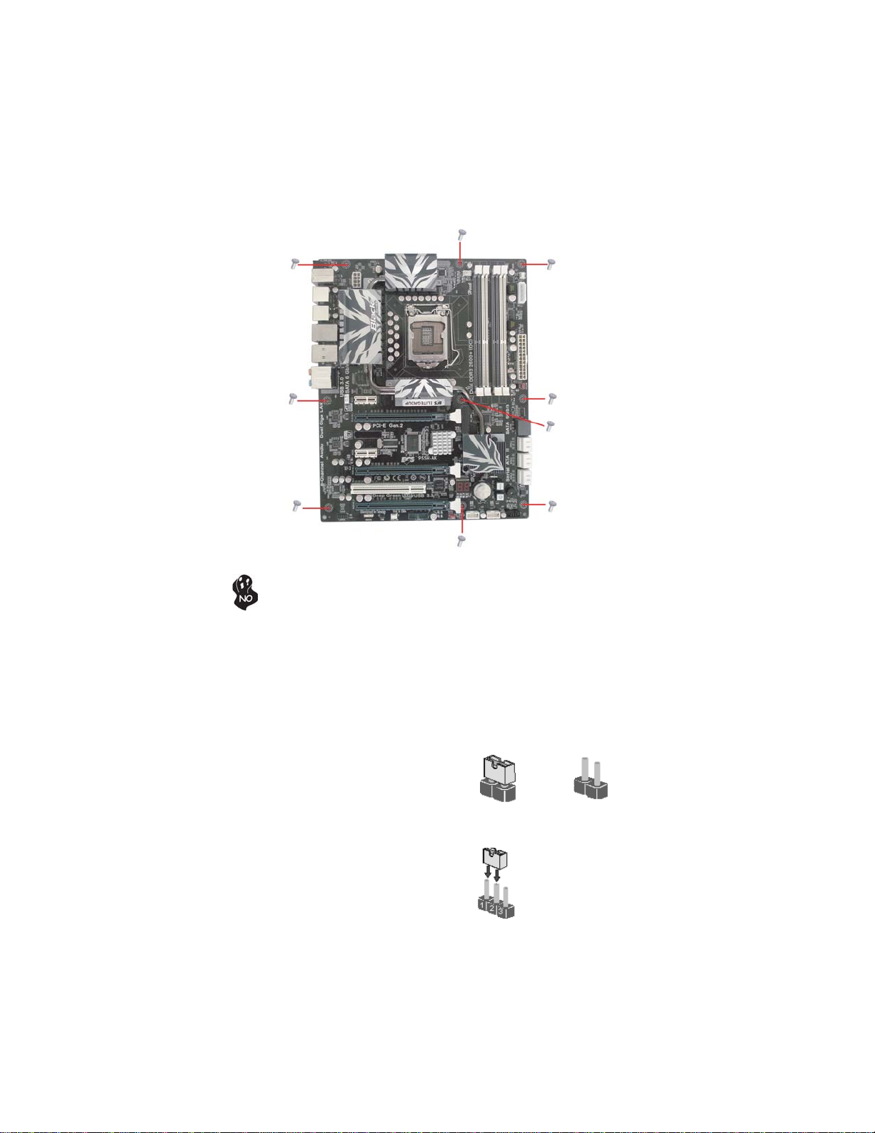
MotherboardComponents

6
IntroducingtheMotherboard
This concludes Chapter 1. The next chapter explains how to install the motherboard.
LABE
L
COMPONENTS
1. CPU Socket
Intel® Core™ i7 / Core™ i5 / Core™ i3 /
Pentium series processor in the LGA1156
package
2. CPU_FAN CPU cooling fan connector
3. DDR3_2/1/4/3 240-pin DDR3 SDRAM slots
4. PWR_FAN Power cooling fan connector
5. ATX4P Auxiliary power connector for graphics card
6. ATX_POWER Standard 24-pin ATX power connector
7. SYS_FAN System cooling fan connector
8. SATA6G Serial ATA 6.0Gb/s connector
9. SATA1~6 Serial ATA 3.0Gb/s connectors
10. RST_BTN Reset button
11. PWR_BTN Power on button
12. F_PANEL Front panel switch/LED header
13. F_USB1~2 Front panel USB 2.0 headers
14. CLR_CMOS Clear CMOS jumper
15. F_USB3.0 Front panel USB 3.0 header
16. CASE_FAN Case cooling fan connector
17. SPDIFO SPDIF out header
18. F_AUDIO Front panel audio header
19. PCI1 32-bit add-on card slot
20. PCIE16X_1~3 PCI Express slots for graphics interface
21. PCIE1~2 PCI Express x1 slots
22. ATX12V 8-pin +12V power connector
Table of Motherboard Components

7
InstallingtheMotherboard
Chapter2
InstallingtheMotherboard
SafetyPrecautions
• Follow these safety precautions when installing the motherboard
• Wear a grounding strap attached to a grounded device to avoid dam-
age from static electricity
• Discharge static electricity by touching the metal case of a safely
grounded object before working on the motherboard
• Leave components in the static-proof bags they came in
• Hold all circuit boards by the edges. Do not bend circuit boards
ChoosingaComputerCase
There are many types of computer cases on the market. The motherboard complies
with the specifications for the ATX system case. Some features on the motherboard
are implemented by cabling connectors on the motherboard to indicators and switches
on the system case. Make sure that your case supports all the features required.
Most cases have a choice of I/O templates in the rear panel. Make sure that the I/O
template in the case matches the I/O ports installed on the rear edge of the
motherboard.
This motherboard carries an ATX form factor of 305 x 244 mm. Choose a case that
accommodates this form factor.
InstallingtheMotherboardinaCase
Refer to the following illustration and instructions for installing the motherboard in
a case.
Most system cases have mounting brackets installed in the case, which correspond
the holes in the motherboard. Place the motherboard over the mounting brackets
and secure the motherboard onto the mounting brackets with screws.
Ensure that your case has an I/O template that supports the I/O ports and expansion
slots on your motherboard.
8
InstallingtheMotherboard
CheckingJumperSettings
This section explains how to set jumpers for correct configuration of the motherboard.
SettingJumpers
Use the motherboard jumpers to set system configuration options. Jumpers with
more than one pin are numbered. When setting the jumpers, ensure that the jumper
caps are placed on the correct pins.
The illustrations show a 2-pin jumper. When
the jumper cap is placed on both pins, the
jumper is SHORT. If you remove the jumper
cap, or place the jumper cap on just one pin,
the jumper is OPEN.
This illustration shows a 3-pin jumper. Pins
1 and 2 are SHORT.
SHORT OPEN
Do not over-tighten the screws as this can stress the motherboard.
9
InstallingtheMotherboard
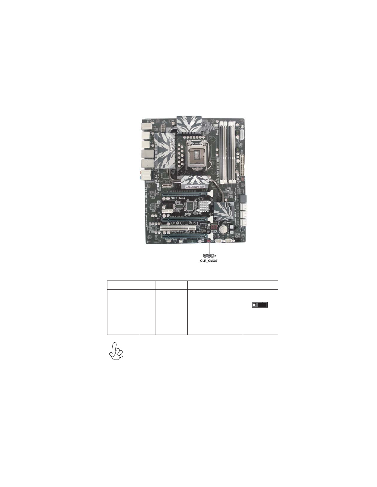
Checking Jumper Settings
The following illustration shows the location of the motherboard jumpers. Pin 1 is
labeled.
JumperSettings
Jumper Type Description Setting (default)
CLR_CMOS 3-pin Clear CMOS
1-2: NORMAL
2-3: CLEAR CMOS
Before clearing the
CMOS, make sure to
turn off the system.
1
CLR_CMOS
To avoid the system unstability after clearing CMOS, we recommend users
to enter the main BIOS setting page to “Load Default Settings” and then
“Save and Exit Setup”.

10
InstallingtheMotherboard
InstallingHardware
Installing the Processor
Caution: When installing a CPU heatsink and cooling fan make sure that
you DO NOT scratch the motherboard or any of the surface-mount resis-
tors with the clip of the cooling fan. If the clip of the cooling fan scrapes
across the motherboard, you may cause serious damage to the motherboard
or its components.
On most motherboards, there are small surface-mount resistors near the
processor socket, which may be damaged if the cooling fan is carelessly
installed.
Avoid using cooling fans with sharp edges on the fan casing and the clips.
Also, install the cooling fan in a well-lit work area so that you can clearly
see the motherboard and processor socket.
Before installing the Processor
This motherboard automatically determines the CPU clock frequency and system bus
frequency for the processor. You may be able to change the settings in the system
Setup Utility. We strongly recommend that you do not over-clock processors or
other components to run faster than their rated speed.
This motherboard has an LGA1156 socket. When choosing a processor, consider the
performance requirements of the system. Performance is based on the processor
design, the clock speed and system bus frequency of the processor, and the quantity
of internal cache memory and external cache memory.
Warning:
1. Over-clocking components can adversely affect the reliability of the
system and introduce errors into your system. Over-clocking can perma-
nently damage the motherboard by generating excess heat in components
that are run beyond the rated limits.
2. Always remove the AC power by unplugging the power cord from the
power outlet before installing or removing the motherboard or other
hardware components.
Fail-Safe Procedures for Over-clocking
When end-users encounter failure after attempting over-clocking, please take the
following steps to recover from it.
1. Shut down the computer.
2. Press and hold the “Page Up Key (PgUp)” of the keyboard, and then boot the PC
up.
3. Two seconds after the PC boots up, release the “Page Up Key (PgUp)”.
4. The BIOS returns to the default setting by itself.

11
InstallingtheMotherboard
A. Opening of the Load Plate
· Put your thumb on the tail of the load
plate and press the tail down.
· Rotate the load plate to fully open
position.
B. Disengaging of the Load Lever
· Hold the hook of lever and pull it to the
left side to clear retention tab.
· Rotate the load lever to fully open
position.
C. Removing the Cap
· Be careful not to touch the contact at
any time.
D. Inserting the Package
· Graspthe package.Ensure tograsp on
the edge of the substrate.
· Make sure pin 1 indicator is on your
bottom-left side.
· Aimatthesocketandplacethepackage
carefully into the socket by purely
vertical motion.
E. Closing the Load Plate
· Rotate the load plate onto the package
IHS (Intergraded Heat Spreader).
· Engage the load lever while pressing
down lightly onto the load plate.
· Secure the load lever with the hook
under retention tab.
F. Fasten the cooling fan supporting base
onto the CPU socket on the motherboard.
G. Make sure the CPU fan is plugged to the
CPU fan connector. Please refer to the
CPU cooling fan user’s manual for more
detail installation procedure.
CPU Installation Procedure
The following illustration shows CPU installation components.

12
InstallingtheMotherboard
Installing Memory Modules
This motherboard accommodates four memory modules. It can support four 240-pin
DDR3 2400 (OC)/ DDR3 2200 (OC)/DDR3 2133 (OC)/DDR3 2000 (OC)/DDR3
1800 (OC)/1600 (OC)/1333/1066 SDRAM. The total memory capacity is 16 GB.
You must install at least one module in any of the four slots. Total memory capacity
is 16 GB.
DDR3 SDRAM memory module table
Memory module Memory Bus
DDR3 2400 1200 MHz
ff Channel A: DDR3_1, DDR3_3
Channel B: DDR3_2, DDR3_4
The four DDR3 memory sockets (DDR3_1, DDR3_2, DDR3_3 and DDR3_4) are
divided into two channels and each channel has two memory sockets as following:
1. To achieve better airflow rates and heat dissipation, we suggest that
you use a high quality fan with 3800 rpm at least. CPU fan and
heatsink installation procedures may vary with the type of CPU fan/
heatsink supplied. The form and size of fan/heatsink may also vary.
2. DO NOT remove the CPU cap from the socket before installing a
CPU.
3. Return Material Authorization (RMA) requests will be accepted
only if the motherboard comes with the cap on the LGA1156 socket.
Due to Intel CPU spec definition, the system will not boot if only one
DIMM is installed in DDR3_2 or DDR3_4. Follow the table above for
recommended memory configuration.
Recommend memory configuration
ff
DDR3_2 DDR3_1 DDR3_4 DDR3_3
1 DIMM -- Populated -- --
1 DIMM -- -- -- Populated
2 DIMMs -- Populated -- Populated
3 DIMMs Populated Populated -- Populated
3 DIMMs -- Populated Populated Populated
4 DIMMs Populated Populated Populated Populated
Mode Sockets
13
InstallingtheMotherboard
Do not remove any memory module from its antistatic packaging
until you are ready to install it on the motherboard. Handle the
modules only by their edges. Do not touch the components or metal
parts. Always wear a grounding strap when you handle the modules.
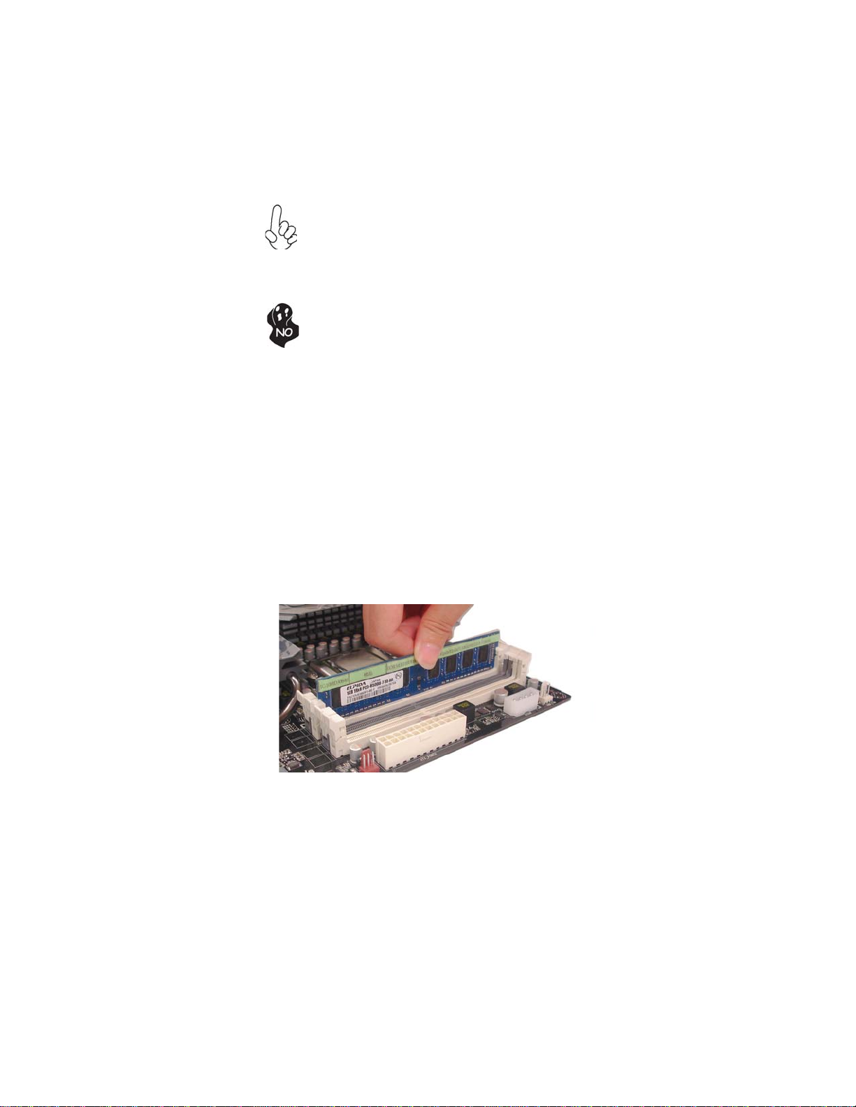
Installation Procedure
Refer to the following to install the memory modules.
1 This motherboard supports unbuffered DDR3 SDRAM .
2 Push the latches on each side of the DIMM slot down.
3 Align the memory module with the slot. The DIMM slots are keyed with
notches and the DIMMs are keyed with cutouts so that they can only be
installed correctly.
4 Check that the cutouts on the DIMM module edge connector match the
notches in the DIMM slot.
5 Install the DIMM module into the slot and press it firmly down until it
seats correctly. The slot latches are levered upwards and latch on to
the edges of the DIMM.
6 Installany remaining DIMM modules.
1. For best performance and compatibility, we recommend that users
give priority to the white DIMMs (DDR3_1/DDR3_3) when installing
DIMMs.
2. We suggest users not mix memory type. It is recommended to use
the same brand and type memory on this motherboard.
14
InstallingtheMotherboard
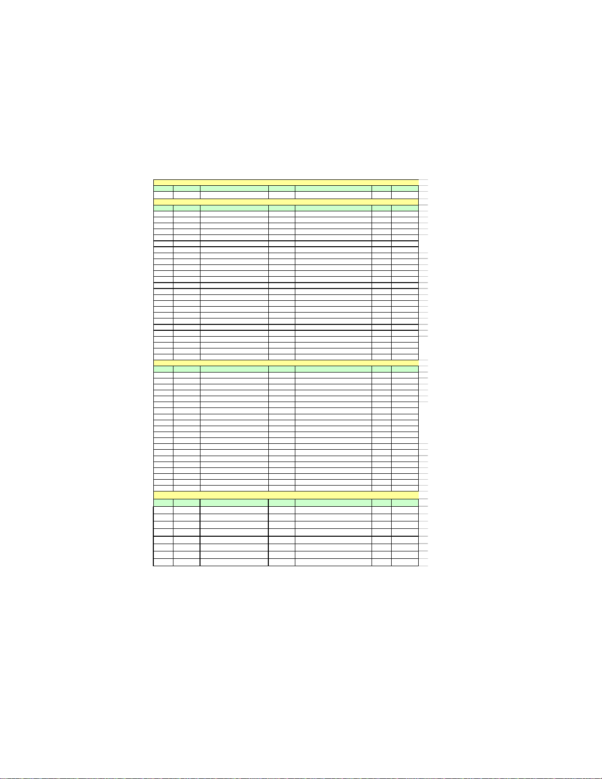
Table A: DDR3 (memory module) QVL(Qualified Vendor List)
The following DDR3 memory modules have been tested and qualified for use with
this motherboard.
NO. Vendor Module part number IC Brand IC Chip Number SS/DS Size
1 Qimonda IMSH51U03A1F1C-08EQimonda IDSH51-03A1F1C-OBESS 512MB
NO. Vendor Module part number IC Brand IC Chip Number SS/DS Size
1 Elixir M2Y2G64CB8HC9N-BE DS 2GB
2 Elixir M2Y2G64CB8HC5N-BE elixir N2CB1G80CN-BE DS 2GB
3 Hynix HMT112U6AFP8C-G7N0 AA Hynix H5TQ1G83AFP G7C SS 1GB
4 Hynix HMT125U6AFP8C-G7N0 AA Hynix H5TQ1G83AFP G7C DS 2GB
5 Kingston KVR1066D3N7 Elpida J5308BASE-AE-E 07500W220 DS 1GB
6 Micron MT8JTF12864AY-1G1D1 Micron 7UD22D9JNL SS 1GB
7 Micron MT8JTF12864AY-1G1D1 Micron 8TD22 D9JNL SS 1GB
8 Micron MT16JTF25664AY-1G1D1 Micron 8WD22 D9JNL DS 2GB
9 Micron MT16JTF25664AZ-1G1F1 Micron 9EF22 D9KPV DS 2GB
10 Micron MT8JTF12864AZ-1G1F1 Micron 9NF22 D9KPT SS 1GB
11 Ramaxel RMR1810NA48E7F-1066-LF NANYA NT5CB128H8AN-DE SS 1GB
12 Kingston KVR1066D3N7/512
Elpida
J5308BASE-AE-E 07340W065
SS 512MB
13 Qimonda IMSH1GU03A1F1C-10F Qimonda IDSH1G-03A1F1C-10F FSS15085 SS 1GB
14 Qimonda IMSH1GU03A1F1C-10G Qimonda IDSH1G-03A1F1C-10G FSS14526 SS 1GB
15 Qimonda IMSH2GU13A1F1C-10F Qimonda IDSH1G-03A1F1C-10F FSS15085 DS 2GB
16 Qimonda IMSH2GU13A1F1C-10G Qimonda IDSH1G-03A1F1C-10G FSS13467 DS 2GB
17 Hynix HYMT112U64ZNF8-G8 AA
Hynix HY5TQ1G831ZN FP-G8
SS 1GB
18 Micron MT16JTF25664AY-1G1D1 Micron 7UD22D9JNL DS 2GB
19 Samsung M378B2873EH1-CF8 SEC HCF8K4B1G0846E SS 1GB
20 Samsung M378B2873DZ1-CF8 SEC HCF8 K4B1G0846D SS 1GB
21 Samsung M378B5673DZ1-CF8 SEC K4B1G0846D HCF8 DS 2GB
22 Aeneon AEH760UD00-10FA98X Aeneon AEH93R10F 0737 SS 1GB
23 Elpida EBJ10UE8BDF0-AE-F Elpida J1108BDSE-DJ-F SS 1GB
24 Elpida EBJ21UE8BDF0-AE-F Elpida J1108BDSE-DJ-F DS 2GB
25 Elpida PC3-8500U-7-00-AP Elpida J53088ASE-AC-E SS 512MB
NO. Vendor Module part number IC Brand IC Chip Number SS/DS Size
1 Apacer 78.A1GC6.9L1 Apacer AM5D5808ADWSBG DS 2GB
2 Elixir M2F2G64CB8HA4N-CG Elixir N2CB1G80AN-CG 0903 DS 2GB
3 Elixir M2Y2G64CB8HC9N-CG DS 2GB
4 Elixir M2F2G64CB88B7N-CG Elixir N2CB2G80BN-CG SS 2GB
5 Elixir M2F4G64CB8HB5N-CG Elixir N2CB2G80BN-CG DS 4GB
6 Hynix HMT112U6AFP8C-H9N0 AA Hynix H5TQ1G83AFP H9C SS 1GB
7 Hynix HMT125U6AFP8C-H9N0 AA Hynix H5TQ1G83AFP H9C DS 2GB
8 Hynix HMT112U6TFR8C-H9N0 Hynix H5TQ1G83TFRH9C SS 1GB
9 G.SKILL F3-10666CL9D-4GBRL DS 2GB
10 G.SKILL F3-10666CL8D-4GBECO 1.35V DS 2GB
11 G.SKILL F3-10666CL9D-4GBN
Q
DS 2GB
12 Kingston KVR1333D3N9/4G Hynix Hynix/H5TQ2G83AFR DS 4GB
13 Nanya NT2GC64B8HAONF-CG Elixir N2CB1G80AN-CG DS 2GB
14 Micron MT8JTF12864AY-1G4D1 Micron 8UD22 D9JNM SS 1GB
15 Micron MT16JTF25664AY-1G4D1 Micron 8WD22 D9JNM DS 2GB
16 Micron MT8JTF12864AZ-1G4F1 Micron 9MF22 D9KPT SS 1GB
17 Samsung M378B2873FHS-CH9 SEC K4B1G0846F SS 1GB
18 Samsung M378B5673FH0-CH9 SEC K4B1G0846F DS 2GB
19 Samsung M378B5273CH0-CH9 SEC K4B2G0846C DS 4GB
20 Nanya M2Y2G64TU8HD5B-BD elixir N2CB1G80AN-CG DS 2GB
DDR3 1333
NO. Vendor Module part number IC Brand IC Chip Number SS/DS Size
1 Aeneon AXH760UD00-13GA98XSS 1GB
2 KingMax FLFD45F-B8KG9 NAUSKingMax KFB8FNGXF-ANX-15USS 1GB
3 KingMax FLFE85F-B8KG9 NEUSKingM ax KFB8FNGXF-ANX-15UDS 2GB
4 KingMax FLFD45F-B8KG9 NAES KingMax KFB8FNGXF-ANX-15A SS 1GB
5 KingMax FLFE85F-B8KG9 NEES KingMax KFB8FNGXF-ANX-15A DS 2GB
6 KingMax FLFE85F-B8KL9 KingMax KFB8FNLXF-BNF-15A DS 2GB
7 KingMax FLFD45F-B8KL9 KingMax KFB8FNLXF-BNF-15A SS 1GB
8 Kingston KVR1333D3N9 Kingston 128X8DDR3 SL0931 DS 2GB
DDR3 1066
DDR3 1333
DDR3 800
Table of contents
Other ECS Motherboard manuals


