ECS P5TX-Apro User manual

P5TX-Apro Mainboard
User’s Manual

Version 2.0
Copyright © May 1997 All rights reserved
Portions copyright Electronic Publishing Services from Delta Projects Ltd.
Thispublicationmaynotbecopied,reproduced,translated,transmittedorreducedtoanyprinted
or electronic medium or to any machine readable form, or stored in a retrieval system, either in
whole or in part without the written consent of the copyright holders.
The contents of this publication are subject to change. The manufacturer reserves the right to
alter the contents of this publication at any time and without notice. The contents of this publica-
tion may contain inaccuracies or typographical errors and is supplied for informational use only.
Products are noted in this publication for identification purposes only. Microsoft is a registered
trademark and Windows is a trademark of Microsoft Corporation. Pentium is a trademark of Intel
Corporation. All other product names or brands may be trademarks or registered trademarks of
their respective holders.

P5TX–Apro User’s Manual
Table Of Contents –III
1: P5TX-Apro Package & Product Information ......................................1 - 1
About This Manual...............................................................................................1 - 1
Acrobat Document Features ....................................................................................... 1 - 1
Manual Features......................................................................................................... 1 - 2
Package Contents .............................................................................................. 1 - 3
Component Information .....................................................................................1 - 6
Expansion Cards & Slots ............................................................................................ 1 - 6
Memory Sockets & Modules.......................................................................................1 - 7
CPU Socket & CPU.......................................................................................................1 - 7
Port & Controller Connections.....................................................................................1 - 7
2: Using Your Mainboard ..................................................................... 2 - 1
System Controls.................................................................................................. 2 - 1
Hardware Controls & Indicators ................................................................................ 2 - 1
CMOS Setup Utility Controls .......................................................................................2 - 3
Hardware Features............................................................................................ 2 - 6
Onboard Ports ............................................................................................................2 - 6
Connectors..................................................................................................................2 - 6
Optional Hardware Connectors.................................................................................2 - 9
Firmware & Software .......................................................................................2 - 10
How To Use The CMOS Setup Utility ........................................................................ 2 - 10
Clearing CMOS ......................................................................................................... 2 - 10
Flashing The BIOS ..................................................................................................... 2 - 12
Bus Master Drivers ................................................................................................... 2 - 12

P5TX–Apro User’s Manual
Table Of Contents – IV
3: Reconfiguring Your Mainboard ........................................................3 - 1
Installing Expansion Cards .................................................................................. 3 - 1
ISA Cards & Slots ........................................................................................................ 3 - 1
Configuring Expansion Card Resources In CMOS Setup ..........................................3 - 2
Adding System Memory .................................................................................... 3 - 6
Memory Configurations .............................................................................................3 - 6
Installing A CPU Upgrade .................................................................................. 3 - 9
The Basic Procedure...................................................................................................3 - 9
Configuring External Clock Speed & Factor............................................................. 3 - 10
Configuring CPU Voltage.......................................................................................... 3 - 10
CPU Jumper Tables & Illustrations ........................................................................... 3 - 12
Adding An IDE Peripheral ................................................................................. 3 - 16
IDE Transfer Modes................................................................................................... 3 - 16
Installing IDE Devices ................................................................................................ 3 - 18
4: P5TX–Apro Reference Information ..................................................4 - 1
Using This Section...............................................................................................4 - 1
Jumper Configuration Summary........................................................................ 4 - 3
Supported CPUs ................................................................................................4 - 8
Interpreting CPU Markings.........................................................................................4 - 9
System Memory Specifications..........................................................................4 - 11
Memory Configurations ............................................................................................4 - 11
CMOS Setup Utility Summary...........................................................................4 - 12
Using the CMOS Setup Utility ................................................................................... 4 - 12
Accessing The CMOS Setup Utility ........................................................................... 4 - 12
Standard CMOS Setup.............................................................................................. 4 - 16
BIOS Features Setup ................................................................................................ 4 - 20
Chipset Features Setup............................................................................................ 4 - 25
Power Management Setup......................................................................................4 - 27
PNP/PCI Configuration ............................................................................................ 4 - 34
PC Health Monitor ................................................................................................... 4 - 42

P5TX-Apro User’s Manual
1: Package & Product Information – 1.1
P5TX-Apro Package & Product Information
This manual contains all the information you’ll need to use
the P5TX-Apro mainboard. Please take a moment to familiarize
yourself with the design and organization of the manual.
About This Manual
This manual is designed mainly as an online document. In
additionto reading iton yourdisplay screen yourcan alsoprintit
out. In some circumstances, you may have received this manual
as a printed document, in which case you can skip the following
section about the online version.
Acrobat Document Features
This manual is in Adobe Acrobat format. It requires Adobe
Acrobat Reader version 3.0 or later to view it. Acrobat Reader for
Microsoft Windows95issupplied onthe SupportCD-ROM disk
that contains this manual. It is installed on the Support CD and
there is also an installation file that will automatically run the
AcrobatReaderinstallerprogram toinstalliton yoursystemhard
disk.If you were notaware of this, youareprobably viewing this
document from the Support CD installation and Reader loaded
automatically when you opened this manual.
If this is the case, you may want to install Acrobat Reader on
your system hard disk. You can copy the Manual directory over
as well so that the manual is readily available without having to
hunt up the Support CD when you want to view it.
If you are unfamiliar with Acrobat Reader, please take a mo-
ment to view the Reader Online Guide which is available under
the Help menu when you run Reader.
The README file in the Manual directory on the Support CD
explains what to do if you need to view this document under an
OS other than Windows95.
In This Section:
About This Manual
Package Contents
Component Information

P5TX-Apro User’s Manual
1: Package & Product Information – 1.2
Manual Features
The online version of this manual provides some additional
navigation features not available in a conventional print docu-
ment. You can click on entries in the Table of Contents and jump
to that location in the manual. In addition, there are buttons at
various points in the manual that are shortcuts to the topic dis-
played on the button.
This manual also uses some icons to call your attention to
important information. The icons appear in the sidebar and rep-
resent the following:
• Important information
• A recommendation or good idea
• A warning or bad idea
• Danger warning
If You Have The Printed Manual
Obviously it is not possible to provide the additional naviga-
tion features in print form. In order that you can still find things
with relative ease, where appropriate we have noted the loca-
tions of additional information referred to.
C
D
G
N

P5TX-Apro User’s Manual
1: Package & Product Information – 1.3
Package Contents
The P5TX–Apro mainboard package contains the following
items, as noted in the Quick Installation Guide (which comes
with the CD Documentation version of the mainboard.). We’ve
listed them here again for your convenience. Please inspect the
package contents and confirm that everything is there. If any-
thing is missing or damaged, call your vendor for instructions
before proceeding. The package includes:
• P5TX–Apro Mainboard
• Cable Pack:
– 1 Floppy Controller Cable
– 1 IDE Controller Cable
• Support Disk:
– Driver Files Folder
– Manual Folder
– Adobe Acrobat Folder
The mainboard comes with IDE Bus Master drivers for sev-
eral Operating Systems. The drivers are organized in individual
folders by OS. In each folder there is a “readme” file that explains
how to install the driver. Please locate the folder for the driver
you need and check this file.
Documentation Versions
If you received this manual
stored on a CD Support Disk,
you will also have received a
printed “Quick Installation”
Guide.Ifyouhavetheprinted
version,theSupportDiskmay
notbeaCD.Ifso,themanual
and Acrobat folders will not
be on the disk.
P5TX-Apro User’s Manual
1: Package & Product Information – 1.4
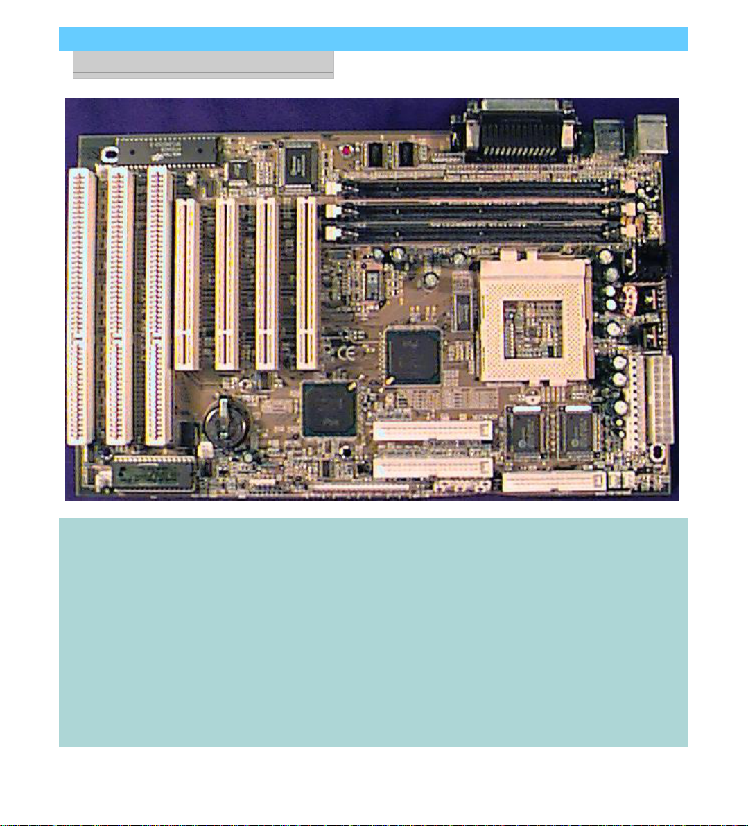
P5TX-Apro
You can use the photograph
andtheillustrationonthenext
page to familiarize yourself
with the components on the
P5TX–Apro mainboard.
TheEnhancedIDEandFloppy
Disk Drive connectors have a
notchinonesidetoorientthe
cables correctly.
The mainboard comes with
one IDE cable. If you install
devices on the second IDE
channel with another cable,
it may not have the orienta-
tion extrusion on the side of
the cable connector, which
prevents attaching the cable
incorrectly. Please check the
section on Installing IDE De-
vices for more information.
P5TX-Apro User’s Manual
1: Package & Product Information – 1.5
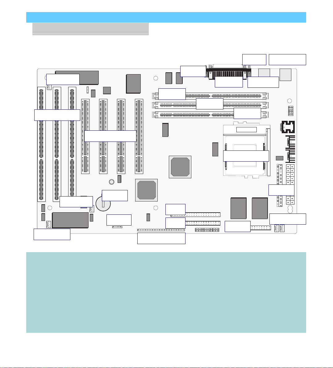
P5TX-Apro Layout
The illustration above shows
the connectors, sockets and
ports and the mainboard.
Socket 7
Power
Floppy
IDE 1
IDE 2
COM2
COM1
Parallel
KB/Mouse
CPU Socket 7
PCI Slots 4 3 2 1
Battery
ISA Slots 3 2 1
Intrusion USB Port
DIMM3
DIMM2
DIMM1
IR Port
Case Features
Fan Power
Wake Up
Fan Power
The COM1 and COM2 ports
are underneath the Parallel
port. The USB ports and the
PS/2 Keyboard and Mouse
ports are stacked one above
the other.
The Intrusion and Wake-up
connectors are for signal
cables that are monitored by
the onboard sensor.
The ATX power connector is
on the right in this view.

P5TX-Apro User’s Manual
1: Package & Product Information – 1.6
Component Information
This section is a brief description of the components on the
mainboard that you might need to know about if you want to
upgrade or change your system configuration. If your mainboard
is already installed in a system, it isn’t necessary for you to re-
view this section.
This mainboard uses the ATX ‘form factor’, a design that inte-
grates many features onto the board including some number of
external ports.
Expansion Cards & Slots
The mainboard has seven expansion slots for system expan-
sion or ‘add-on’ cards. Three of them are ISA slots, the other four
arePCI slots.When youget anexpansion card,it mustuseone of
these to connect to the computer.
The ISA expansion slots are a legacy of the original IBM PC/
AT design.Theyare 16-bitslotsthat runat amoderatebus speed.
There are many kinds of expansion cards that use this slot design
to connect to the computer, some of the most common being
sound and modem cards.
PCI slots are the current high-speed 32-bit standard for sys-
tem expansion cards. They operate at a faster speed and have a
greater data throughput than ISA cards.
Expansion cards often make use of system resources, which
requiresmanagingthesystemresourceconfiguration.Mostnewer
expansion cards support the ‘Plug and Play’ standard that allows
an Operating System like Windows95 to automatically detect
them and configure system resources as needed. Some older ISA
designs may not support this standard and may therefore require
manual configuration. You should consult the specifications or
documentationfor acard todetermine ifthis isthe caseand what
needs do be done to properly configure the card.

P5TX-Apro User’s Manual
1: Package & Product Information – 1.7
Memory Sockets & Modules
There are three memory module sockets on the mainboard.
They use 168-pin DIMM memory modules. The sockets func-
tionindependently ofeach other. Thismainboard hasa veryflex-
ible memory design that allows the use of a variety of memory
options up to a total of 256MB. There is more information about
thisinAddingSystemMemorysectionofSection3:Reconfiguring
Your Mainboard.
CPU Socket & CPU
The Socket 7 CPU socket supports the full range of Pentium®-
class CPUs including MMX Pentiums®. Installing a CPU in the
socket is easy. The lever at the side of the socket latches the CPU
in place when it is down and releases it when raised.
If you want to install a CPU upgrade or are installing a CPU
on the board for the first time, please refer to ‘Installing a CPU’ in
Section 3: Reconfiguring Your Mainboard.
Port & Controller Connections
This mainboard has two external Serial ports, a Parallel port,
two USB (Universal Serial Bus) ports and both a PS/2-type key-
board and mouse port built onto the board. There are also sev-
eral connectors built onto the board. There are connectors for
fourIDEdevicesin two‘channels’andfortwo floppydiskdrives.
There are also connectors on the board for some system case
features, CPU and other cooling fans and some other hardware
features.
Details about these connectors are in Section 4: Reference In-
formation.

P5TX-Apro User’s Manual
1: Package & Product Information – 1.8

P5TX–Apro User’s Manual
2: UsingYourMainboard–2.1
Using Your Mainboard
This section covers the following topics:
• System Controls & Indicators
• Hardware Features
• Firmware & Software
Theygo over thesystem control featuresand status indicators
that derive from the mainboard and explain the software that
comes with or is built-into the mainboard
System Controls
There are two topics in this section, a explanation of the hard-
ware controls and status indicators that connect from the main-
board to your system case and some information about the parts
of the CMOS Setup Utility that allow you customize some sys-
tem features.
Hardware Controls & Indicators
Therearesomecontrol featuresandstatusindicators thatcon-
nect from the mainboard to your system case, which is some-
times called the ‘Enclosure’ or ‘Chassis.’ These are:
• Power Switch
• Power Status Indicator
• Suspend Switch
• Suspend Status Indicator
• Reset Switch
• Hard Disk Drive Activity Indicator
• Keyboard Lock
All of these case features connect to the mainboard via con-
nector strip J10. Not all system cases have all of these features, so
your system may not have all of them. The functions and op-
tions for these are shown in the table on the next page.
In This Section:
System Controls
Hardware Features
Firmware & Software

P5TX–Apro User’s Manual
2: UsingYourMainboard–2.2
Hardware Control & Indicator Connectors
Feature J10 Pins Function
Power Status LED 1-3 When lighted indicates that system is turned on
Pin 1: + ; Pin 2: + ; Pin 3: –
Suspend Switch 4-5 Puts the system into Suspend state under Operating
Systems that support this power management feature
Suspend LED 6-8 When lighted indicates the system is suspended
Pin 1: + ; Pin 2: + ; Pin 3: –
Reset Switch 9-10 Pressing the Reset switch restarts the system
Keyboard Lock 11-12 Disables keyboard via a lock mounted on front panel
of the case
Speaker 13-16 Connects to the PC speaker mounted on the system case
Pin 1: +
HDD Activity LED 17-18 Flashes when hard disk drive is active
Pin 1: + ; Pin 2: –
Power Switch 19-20 Turns the system power on and off. Default sets this
to dual function as power and suspend switch. Press
once for Suspend, hold for >4 seconds for Off. To set as
Power only, change setting in the Power Management
section of the CMOS Setup utility.

P5TX–Apro User’s Manual
2: UsingYourMainboard–2.3
CMOS Setup Utility Controls
Two sections of the CMOS Setup Utility allow you to config-
ure how some of your system’s features work. These are:
• BIOS Features Setup
• Power Management Setup
The CMOS Setup Utility is a program that is permanently
stored in the BIOS chip on the mainboard. The utility creates a
system hardware configuration record that it stores in a small
amount of battery-supported memory on the board. The BIOS
uses this record to function as an interface between the system
hardware and the operating system. Most of the settings in the
CMOS Setup Utility are made automatically, so you won’t nor-
mally need to use this program. You can, however, customize
some of the operational features to suit how you prefer to use
the system.
Thescreen illustrations on thenext two pages showtheSetup
Default settings for these two sections of the utility.
The CMOS Setup Utility Summary in Section 4: Reference
Information, lists the setting options for each section of the util-
ity including the two noted above.

P5TX–Apro User’s Manual
2: UsingYourMainboard–2.4
CMOS Setup Utility –
BIOS Features Setup
This section of the setup util-
ity allows you to configure
somesystemfeaturesinclud-
ing Virus Warning, Boot Se-
quence and Security Option.
Virus Warning –
When enabled, monitors the
primary hard disk boot sec-
torand warns of anyattempt
to write to it.
Boot Sequence –
Controls the order in which
thesystemchecksdiskdrives
for a boot disk.
Security Option –
Sets the level of password
protection for the system.
P5TX–Apro User’s Manual
2: UsingYourMainboard–2.5
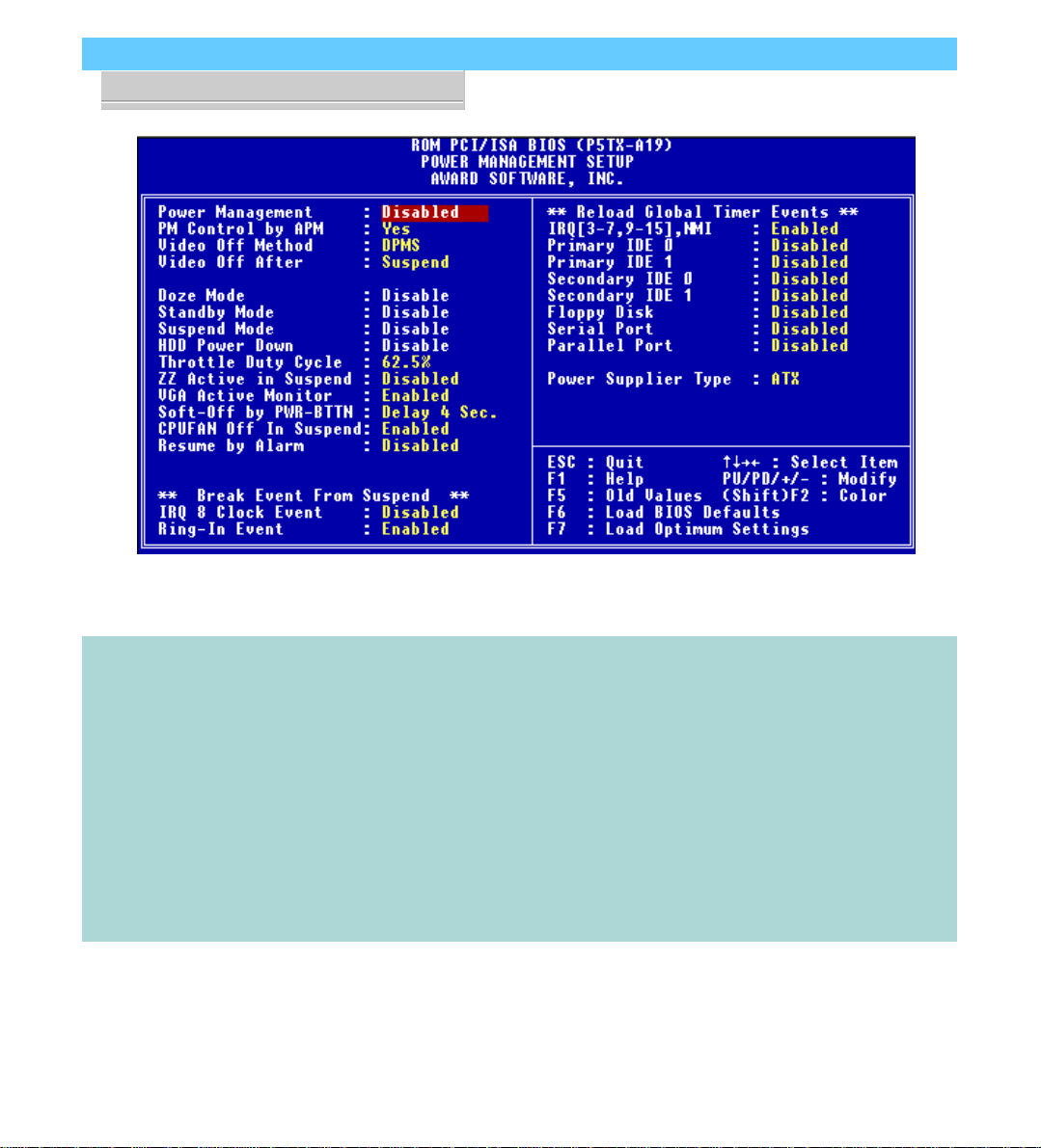
CMOS Setup Utility –
Power Management Setup
This section of the setup util-
ityallowsyoutoconfigurethe
powermanagementfeatures
supportedbytheBIOS.These
can also operate in tandem
withOperatingSystempower
management features.
You can use the Min Saving
orMaxSavingdefaultmodes
or you can configure the
powermanagementfeatures
individuallyintheUserDefine
mode.

P5TX–Apro User’s Manual
2: UsingYourMainboard–2.6
Hardware Features
This section is a brief overview of information about the
mainboard’s hardware features that connect to external devices.
Onboard Ports
Therearefiveexternalportson themainboard.Theseareports
standard to most personal computers:
• COM1 Serial Port
A high-speed serial port which can also be configured as the
COM3 port in the CMOS Setup Utility.
• COM2 Serial Port
A high-speed serial port which can also be configured as the
COM4 port in the CMOS Setup Utility.
• Parallel Port
The parallel port can be configured as a Standard, ECP or EPP
parallel port in the CMOS Setup Utility
• PS/2 Keyboard Port & PS/2 Mouse Port (stacked)
• USB ports – two ports (stacked)
Connectors
Thereare several connectors onthe mainboard for connecting
additional ports and internal peripheral devices
• IDE 1 – Primary IDE Channel
A high-speed serial port which can also be configured as the
COM3 port in the CMOS Setup Utility.
• IDE 2 – Secondary IDE Channel
A high-speed serial port which can also be configured as the
COM4 port in the CMOS Setup Utility.
• Floppy Connector
The parallel port can be configured as a Standard, ECP or EPP
parallel port in the CMOS Setup Utility

P5TX–Apro User’s Manual
2: UsingYourMainboard–2.7
CMOS Setup Utility –
Integrated Peripherals
This section of the setup util-
ity configures the IDE and
Floppy controllers and the
settingsfor the external ports
Thissectionenablesandcon-
figures the optional USB and
Infrared features.
The screen illustration shows
the settings when Setup De-
faults are loaded.

P5TX–Apro User’s Manual
2: UsingYourMainboard–2.8
Case Security
The mainboard has a case security feature that will warn if the
system case or ‘chassis’ has been opened since the last time the
system was used. There is a photoelectric cell mounted on the
mainboard that is active when the system is turned off and will
detect the case being opened. The next time you turn the system
on a warning message will appear on screen during the POST
(Power On Self Test) before the Operating System loads.
The J18 connector on the mainboard connects to a chassis
intrusion signal cable.
Cooling Fan Connectors
There are three cooling fan connectors on the mainboard that
support cooling fans with power management features. If you
connect this type of fan, and the ‘CPU FAN Off In Suspend’ line
in the CMOS Setup utility’s Power Management Setup section is
set to Enabled, the system will turn the fans off when the system
is in Suspend mode.
Modem Wake-Up
The J19 connector on the mainboard is for connecting a signal
cable from a modem that supports a modem ring system wake
up feature. With such a modem installed and connected to the
mainboard via this connector, the system will wake up from Sus-
pend mode when an incoming call is received by the modem.
The ‘Ring-In Event’ line in the CMOS Setup utility’s Power
Management Setup section must be set to Enabled for this fea-
ture to function.
Power Supply Selection
There are two power supply connectors on the mainboard.
One is for a standard PS/2–type power supply and the other for
anATXpower supply.Youmustindicate whichtypeisconnected
to the mainboard for power management purposes. You do this
by setting the ‘Power Supply Type’ line in the CMOS Setup
utility’s Power Management Setup section to the correct type.
Table of contents
Other ECS Motherboard manuals


Popular Motherboard manuals by other brands


EVGA
EVGA 123-CD-E635 user guide

Gigabyte
Gigabyte AMD Socket AM2 Motherboard GA-3PXSL-RH user manual

ASROCK
ASROCK 4CoreDual-SATA2 R2.0 Specifications

ON Semiconductor
ON Semiconductor MT9M034I12STCVH-GEVB user manual

SOYO
SOYO 6KF User's guide & technical reference

MSI
MSI P7N DIAMOND - Motherboard - ATX user guide


