ECS L4S8A2 User manual

Preface
Copyright
This publication, including all photographs, illustrations and software, is protected
under international copyright laws, with all rights reserved. Neither this manual, nor
any of the material contained herein, may be reproduced without written consent of
the author.
Version 1.1
Disclaimer
The information in this document is subject to change without notice. The
manufacturer makes no representations or warranties with respect to the contents
hereof and specifically disclaims any implied warranties of merchantability or fitness
for any particular purpose. The manufacturer reserves the right to revise this
publication and to make changes from time to time in the content hereof without
obligation of the manufacturer to notify any person of such revision or changes.
Trademark Recognition
Microsoft, MS-DOS and Windows are registered trademarks of Microsoft Corp.
MMX, Pentium, Pentium-II, Pentium-III, Celeron are registered trademarks of Intel
Corporation.
Other product names used in this manual are the properties of their respective owners
and are acknowledged.
Federal Communications Commission (FCC)
This equipment has been tested and found to comply with the limits for a Class B
digital device, pursuant to Part 15 of the FCC Rules. These limits are designed to
provide reasonable protection against harmful interference in a residential installation.
This equipment generates, uses, and can radiate radio frequency energy and, if not
installed and used in accordance with the instructions, may cause harmful interference
to radio communications. However, there is no guarantee that interference will not
occur in a particular installation. If this equipment does cause harmful interference to
radio or television reception, which can be determined by turning the equipment off
and on, the user is encouraged to try to correct the interference by one or more of the
following measures:
− Reorient or relocate the receiving antenna.
− Increase the separation between the equipment and the receiver.
− Connect the equipment onto an outlet on a circuit different from that to which
the receiver is connected.
− Consult the dealer or an experienced radio/TV technician for help.
Shielded interconnect cables and a shielded AC power cable must be employed with
this equipment to ensure compliance with the pertinent RF emission limits governing
this device. Changes or modifications not expressly approved by the system's
manufacturer could void the user's authority to operate the equipment.

Declaration of Conformity
This device complies with part 15 of the FCC rules. Operation is subject to the
following conditions:
− This device may not cause harmful interference, and
− This device must accept any interference received, including interference
that may cause undesired operation.
Canadian Department of Communications
This class B digital apparatus meets all requirements of the Canadian Interference-
causing Equipment Regulations.
Cet appareil numérique de la classe B respecte toutes les exigences du Réglement
sur le matériel brouilieur du Canada.
About the Manual
The manual consists of the following:
Chapter 1
Introducing the Mainboard
Describes features of the mainboard,
and provides a shipping checklist.
Go to ⇒page 1
Chapter 2
Installing the Mainboard
Describes installation of mainboard
components.
Go to ⇒page 8
Chapter 3
Using BIOS
Provides information on using the BIOS
Setup Utility.
Go to ⇒page 28
Chapter 4
Using the Mainboard Software
Describes the mainboard software.
Go to ⇒page 52
ii

T
TA
AB
BL
LE
E
O
OF
F
C
CO
ON
NT
TE
EN
NT
TS
S
Preface i
CHAPTER 1 1
Introducing the Mainboard 1
Introduction.................................................................................................1
Checklist.....................................................................................................2
Standard Items................................................................................................. 2
Features .....................................................................................................3
Choosing a Computer Case .......................................................................5
Mainboard Components .............................................................................6
CHAPTER 2 8
Installing the Mainboard 8
Safety Precautions......................................................................................8
Quick Guide................................................................................................8
Installing the Mainboard in a Case..............................................................9
Checking Jumper Settings..........................................................................9
Setting Jumpers ............................................................................................... 9
Checking Jumper Settings............................................................................. 10
Jumper Settings ............................................................................................. 10
Connecting Case Components........................................................................11
Front Panel Connector................................................................................... 13
Installing Hardware...................................................................................14
Installing the Processor.................................................................................. 14
Installing Memory Modules .......................................................................... 17
Installing a Hard Disk Drive/CD-ROM......................................................... 18
Installing a Floppy Diskette Drive................................................................. 20
Installing Add-on Cards................................................................................. 21
Connecting Optional Devices........................................................................ 23
Connecting I/O Devices............................................................................26
External Connector Color Coding ................................................................. 27
CHAPTER 3 28
Using BIOS 28
About the Setup Utility..............................................................................28
The Standard Configuration .......................................................................... 28
Entering the Setup Utility.............................................................................. 29
Updating the BIOS........................................................................................ 29
Using BIOS...............................................................................................30
Standard CMOS Features.............................................................................. 31
iii

Advanced BIOS Setup Option....................................................................... 33
Advanced Chipset Features Option ............................................................... 36
Integrated Peripherals.................................................................................... 38
Power Management Setup Option................................................................. 43
PNP/PCI Configurations................................................................................ 47
PC Health Status Option................................................................................ 48
Frequency/Voltage Control............................................................................ 49
Load Fail-Safe Defaults Option..................................................................... 50
Load Optimized Defaults Option................................................................... 50
Set Supervisor/User Password....................................................................... 51
Save & Exit Setup Option ............................................................................. 51
Exit Without Saving ...................................................................................... 51
CHAPTER 4 52
Using the Mainboard Software 52
About the Software CD-ROM ...................................................................52
Auto-installing under Windows 98/ME/2000/XP .......................................52
Running Setup............................................................................................... 53
Manual Installation....................................................................................55
Utility Software Reference ........................................................................55
iv

C
Ch
ha
ap
pt
te
er
r
1
1
Introducing the Mainboard
I
In
nt
tr
ro
od
du
uc
ct
ti
io
on
n
Thank you for choosing the L4S8A2 mainboard. The L4S8A2 mainboard is a
high–performance, enhanced function mainboard that supports Socket 478
Pentium 4 processors with system speeds up to 533MHz for high-end
business or personal desktop markets.
The mainboard incorporates the SiS648 Northbridge and SiS963 Southbridge
chipsets. The SiS648 Northbridge chipset provides a 12-level In-Order-Queue
to support maximum outstanding transactions on host up to 12. The memory
controller offers high-bandwidth up to 2.7GB/s under DDR333 in order to
sustain the bandwidth demand from the host processor, as well as the multi
I/O masters and AGP masters. While the SiS963 Southbridge integrates the
Universal Serial Bus 2.0 Host Controllers, 1394a and Audio Controller with AC
97 interface.
The L4S8A2 is designed to give customers an advanced, multimedia solution
at a very low cost. It is equipped with advanced full set of I/O ports, such as
dual channel IDE interfaces, a floppy controller, two high-speed serial port, an
EPP/ECP capable bi-directional parallel port connector, four USB (Universal
Serial Bus) connector, a PS/2 keyboard and mouse connectors. One AGP slot,
five PCI local bus slots and one communication and networking riser (CNR -
optional) slot provide expandability for add-on peripheral cards.
Note: SDRAM provides 800 MBps or 1 GBps data transfer depending on whether
the bus is 100 MHz or 133 MHz. Double Data Rate SDRAM (DDR SDRAM)
doubles the rate to 1.6 GBps or 2.7 GBps by transferring data on both the
rising and falling edges of the clock. DDR SDRAM uses additional power and
ground lines and requires 184-pin DIMM modules rather than the 168-pin
DIMMs used by SDRAM.

C
Ch
he
ec
ck
kl
li
is
st
t
Compare the mainboard’s package contents with the following checklist:
Standard Items
• One mainboard
• One diskette drive ribbon cable (optional)
• One IDE drive ribbon cable
• One auto-install software support CD
• One I/O panel
• One cooling fan retention module
• This user’s manual
2

F
Fe
ea
at
tu
ur
re
es
s
Processor The L4S8A2 mainboard uses a micro PGA 478-pin socket that
has the following features:
• Supports 400/533 MHz system bus
• Supports “Hyper-Threading” technology CPU
• Accommodates Pentium 4 processors at 1.5G/1.6G/1.7G…
2.5G and above
“Hyper-Threading” technology enables the operating system
into thinking it’s hooked up to two processors, allowing two
threads to be run in parallel, both on separate ‘logical’
processors within the same physical processor.
Chipset The SiS648 and SiS963 chipsets are based on an innovative
and scalable architecture with proven reliability and
performance. A few of the chipset’s advanced features are:
• Supports Intel Pentium 4 series CPU with data transfer
rate up to 533MHz
• Support 12 outstanding transactions and out-of-order
completion
• Supports 64-bit high performance DDR333/DDR266
Memory Controller
• Universal AGP v3.0 compliant and supports AGP 8X/4X
Interface with Fast Write Transaction
• Distributed arbitration strategy with long contiguous data
streaming up to 1GB/s
• PCI 2.2 specification compliance
• Integrated multi-threaded I/O link mastering with read
pipelined streaming
• Supports Ultra DMA 33/66/100/133
Additional key features include support for six USB 2.0 ports,
Fast Ethernet MAC controller, AC97 interface, advanced
power management, integrated DMA controller and keyboard
controller.
Memory • Supports DDR SDRAM up to 200/266/333 MHz memory
module
• Accommodates three unbuffered 2.5V 184-pin slots
• Each slot supports up to 1 GB with a total maximum
capacity of 3 GB
AGP The L4S8A2 includes an 8xAGP slot that provides eight times
the bandwidth of the original AGP specification. The AGP 3.0
(8xAGP) offers a significant increase in performance along
with feature enhancements to AGP2.0. This interface
represents the natural evolution from the existing AGP to meet
the ever-increasing demands placed on the graphic interfaces
within the workstation and desktop environments.
AC’ 97 Audio
Codec The AC’ 97 Audio codec is compliant with the AC’ 97 2.2
specification, and supports 18-bit ADC (Analog Digital
Converter) and DAC (Digital Analog Converter) resolution as
well as 18-bit stereo full-duplex codec with independent and
variable sampling rates. Further features include support for
four analog line-level stereo inputs.
3
Expansion
Options The mainboard comes with the following expansion options:
• Five 32-bit PCI slots
• One 8x/4x AGP slot
• A Communications Network Riser (CNR) slot (AC97
interface only) (optional)
• Two IDE connectors which support four IDE channels and
a floppy disk drive interface
The L4S8A2 supports Ultra DMA bus mastering with transfer
rates of 33/66/100/133 MB/sec.
Onboard LAN
(optional) RTL8201BL is a Fast Ethernet Phyceiver with an MII (Media
Independent Interface)/SNI (Serial Network Interface). It can
be used as a Network Interface Adapter, MAU, CNR, ACR,
Ethernet Hub, and Ethernet Switch.
It is incorporated in the chipset providing the mainboard with
10/100Mbps fast Ethernet controller and integrated Ethernet
PCI LAN capabilities.
Integrated I/O The mainboard has a full set of I/O ports and connectors:
• Two PS/2 ports for mouse and keyboard
• Two serial port (COM2 – optional)
• One parallel port
• Four USB ports
• One LAN port (optional)
• Audio jacks for microphone, line-in and line-out
BIOS
Firmware This mainboard uses Award BIOS that enables users to
configure many system features including the following:
• Power management
• Wake-up alarms
• CPU parameters
• CPU and memory timing
The firmware can also be used to set parameters for different
processor clock speeds.
Some hardware specifications and software items are subject to change
without prior notice.
4

C
Ch
ho
oo
os
si
in
ng
g
a
a
C
Co
om
mp
pu
ut
te
er
r
C
Ca
as
se
e
There are many types of computer cases on the market. The mainboard
complies with the specifications for the ATX system case. Some features on
the mainboard are implemented by cabling connectors on the mainboard to
indicators and switches on the system case. Ensure that your case supports
all the features required. The mainboard can support one or two floppy
diskette drives and four enhanced IDE drives. Ensure that your case has
sufficient power and space for all the drives that you intend to install.
Most cases have a choice of I/O templates in the rear panel. Make sure that
the I/O template in the case matches the I/O ports installed on the rear edge
of the mainboard.
This mainboard has an ATX form factor of 305 x 190 mm. Choose a case that
accommodates this form factor.
5
M
Ma
ai
in
nb
bo
oa
ar
rd
d
C
Co
om
mp
po
on
ne
en
nt
ts
s
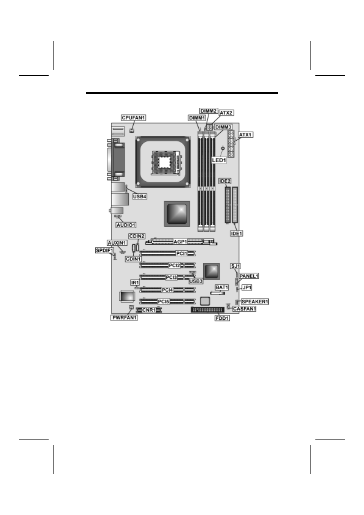
6

Table of Mainboard Components
Label Component
AGP1 Accelerated Graphics Port
ATX1 Standard 20-pin ATX power connector
ATX2 CPU Vcore power connector
AUDIO1 Front audio connector
AUXIN1* Extra line-in connector
BT1 Three volt realtime clock battery
CASFAN1 Case fan connector
CDIN1 Primary CD-in connector
CDIN2* Secondary CD-in connector
CNR1* Communications Networking Riser slot
CPU SOCKET Micro PGA 478-pin socket for Pentium 4 CPUs
CPUFAN1 Cooling fan for CPU
DIMM1, DIMM2,
DIMM3 Three 184-pin DDR SDRAM
FDD1 Floppy disk drive connector
IDE 1 Primary IDE channel
IDE 2 Secondary IDE channel
IR1 Infrared port
JP1 Clear CMOS jumper
LED11Memory module LED
PANEL1 Connector for case front panel switches and LED indicators
PCI1 ~ PCI5 Five 32-bit add-on card slots
PWRFAN1* Power fan connector
SJ1 Single color LED header
SPEAKER1 Speaker connector
SPDIF1* SPDIF out header
USB3 Connector for front panel USB ports
USB4 USB Card Reader header
*Optional component
This concludes Chapter 1. The next chapter explains how to install the
mainboard.
7
1The red indicator LED1 (optional) turns on if your system is still powered,
at which time memory modules cannot be installed or uninstalled.

C
Ch
ha
ap
pt
te
er
r
2
2
Installing the Mainboard
S
Sa
af
fe
et
ty
y
P
Pr
re
ec
ca
au
ut
ti
io
on
ns
s
Follow these safety precautions when installing the mainboard:
• Wear a grounding strap attached to a grounded device to avoid
damage from static electricity.
• Discharge static electricity by touching the metal case of a safely
grounded object before working on the mainboard.
• Leave components in the static-proof bags they came in.
• Hold all circuit boards by the edges. Do not bend circuit boards.
Q
Qu
ui
ic
ck
k
G
Gu
ui
id
de
e
This Quick Guide suggests the steps you can take to assemble your system
with the mainboards.
The following table provides a reference for installing specific components:
Locating Mainboard Components Go to page 6
Installing the Mainboard in a Case Go to page 9
Setting Jumpers Go to page 9
Installing Case Components Go to page 11
Installing the CPU Go to page 14
Installing Memory Go to page 17
Installing an HDD and CD-ROM Drive Go to page 18
Installing an FDD Go to page 20
Installing Add-on Cards Go to page 21
Connecting Options Go to page 23
Connecting Peripheral (I/O) Devices Go to page 26

I
In
ns
st
ta
al
ll
li
in
ng
g
t
th
he
e
M
Ma
ai
in
nb
bo
oa
ar
rd
d
i
in
n
a
a
C
Ca
as
se
e
Refer to the following illustration and instructions for installing the mainboard
in a case:
This illustration shows an
example of a mainboard being
installed in a tower-type case:
Note: Do not overtighten
the screws as this
can stress the
mainboard.
Most system cases have
mounting brackets installed in
the case, which correspond to
the holes in the mainboard.
Place the mainboard over the
mounting brackets and secure
the mainboard onto the
mounting brackets with
screws.
2.
S
ecure the mainboard with
screws where appropriate.
1. Place the mainboard
over the mounting brackets.
Ensure that your case has an I/O template that supports the I/O ports and
expansion slots on your mainboard.
C
Ch
he
ec
ck
ki
in
ng
g
J
Ju
um
mp
pe
er
r
S
Se
et
tt
ti
in
ng
gs
s
This section explains how to set jumpers for correct configuration of the
mainboard.
Setting Jumpers
Use the mainboard jumpers to set system configuration options. Jumpers with
more than one pin are numbered. When setting the jumpers, ensure that the
jumper caps are placed on the correct pins.
The illustrations below show a 2-pin jumper.
When the jumper cap is placed on both pins,
the jumper is SHORT. If you remove the
jumper cap, or place the jumper cap on just
one pin, the jumper is OPEN.
This illustration shows a 3-pin
jumper. Pins 1 and 2 are SHORT.
Short Open
123
9
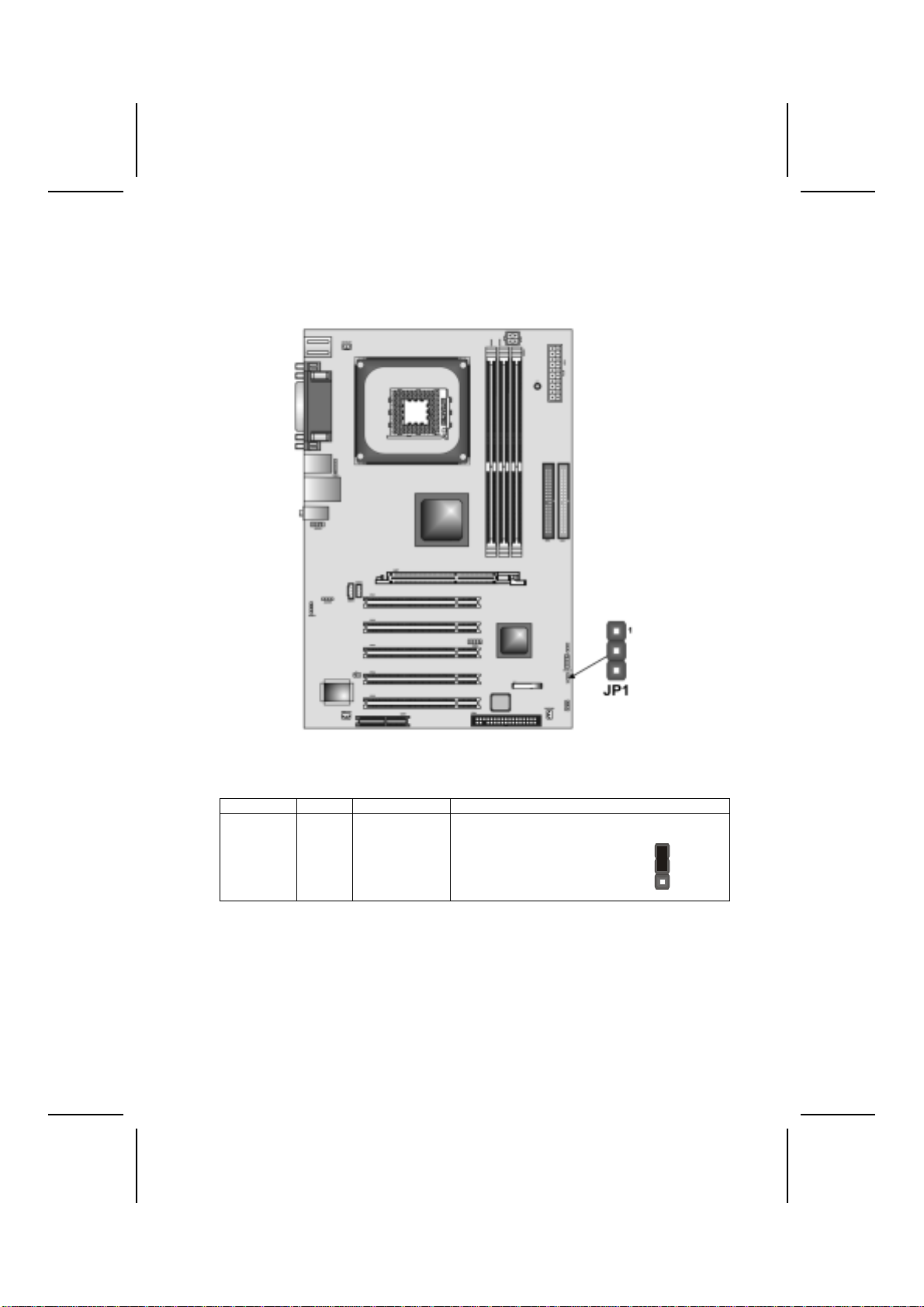
Checking Jumper Settings
The following illustration shows the location of the mainboard jumpers. Pin 1 is
labeled.
Jumper Settings
Jumper Type Description Setting (default)
JP1 3-pin Clear CMOS 1-2: Normal
2-3: Clear CMOS
JP1
1
JP1 – Enables you to clear the BIOS. Follow these instructions:
1. Turn the system off.
2. Short pins 2 and 3 on jumper 1.
3. Return the jumper to the normal setting.
4. Turn the system on. The BIOS is returned to the default
settings.
10
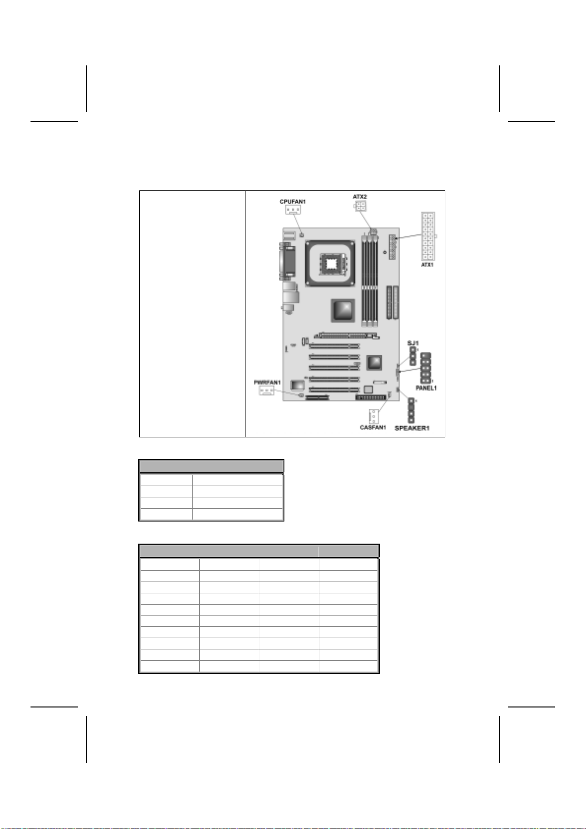
Connecting Case Components
After you have installed the mainboard into a case, you can begin connecting
the mainboard components. Refer to the following:
1. Connect the Pentium
4 processor auxiliary
case power supply
connector to ATX2.
2. Connect the standard
power supply
connector to ATX1.
3. Connect the CPU
cooling fan cable to
CPUFAN1.
4. Connect the power
cooling fan connector
to PWRFAN1
(optional).
5. Connect the case
cooling fan connector
to CASFAN1.
6. Connect the case
switches and indicator
to PANEL1.
7. Connect the case
speaker cable to
SPEAKER1.
8. Connect the case
LED cable to SJ1.
ATX2: ATX 12V Power Connector
Pin Signal Name
1 +12V
2 +12V
3 Ground
4 Ground
ATX1: ATX 20-pin Power Connector
Pin Signal Name Pin Signal Name
1 +3.3V 11 +3.3V
2 +3.3V 12 -12V
3 Ground 13 Ground
4 +5V 14 PS ON#
5 Ground 15 Ground
6 +5V 16 Ground
7 Ground 17 Ground
8 PWRGD 18 +5V
9 +5VSB 19 +5V
10 +12V 20 +5V
11

CPUFAN1/PWRFAN1 (optional)/CASFAN1: FAN Power Connectors
Pin Signal Name Function
1 GND System Ground
2 +12V Power +12V
3 Sense Sensor
SPEAKER1: Internal speaker
Pin Signal Name
1 Signal
2 Key
3 Ground
4 VCC
SJ1: Single color LED header
Pin Signal Name Function
1 ACPI LED MSG LED (-) green
2 ACPI LED MSG LED (-) green
3 SB5V Power LED (+)
ACPI LED function:
S0 S1 S3 S4/S5
SJ1
1Light Blinking Blinking Dark
12

Front Panel Connector
The front panel connector (PANEL1) provides a standard set of switch and
LED connectors commonly found on ATX or micro-ATX cases. Refer to the
table below for information:
PANEL1
Pin Signal Name Function
1 HD_LED_P Hard disk LED (positive)
2 FP PWR/SLP MSG LED [dual color or single color (+)]
3 HD_LED_N Hard disk active LED (negative)
4 FP PWR/SLP MSG LED [dual color or single color (-)]
5 RST_SW_N Reset Switch
6 PWR_SW_P Power Switch
7 RST_SW_P Reset Switch
8 PWR_SW_N Power Switch
9 RSVD Reserved
10 NC No pin
Hard Drive Activity LED
Connecting pins 1 and 3 to a front panel mounted LED provides visual
indication that data is being read from or written to the hard drive. For the LED
to function properly, an IDE drive should be connected to the onboard IDE
interface. The LED will also show activity for devices connected to the SCSI
(hard drive activity LED) connector.
Power / Sleep / Message Waiting LED
Connecting pins 2 and 4 to a single- or dual-color, front panel mounted LED
provides power on/off, sleep, and message waiting indication.
Reset Switch
Supporting the reset function requires connecting pins 5 and 7 to a
momentary-contact switch that is normally open. When the switch is closed,
the board resets and runs POST.
Power Switch
Supporting the power on/off function requires connecting pins 6 and 8 to a
momentary-contact switch that is normally open. The switch should maintain
contact for at least 50 ms to signal the power supply to switch on or off. The
time requirement is due to internal debounce circuitry. After receiving a power
on/off signal, at least two seconds elapses before the power supply
recognizes another on/off signal.
13

I
In
ns
st
ta
al
ll
li
in
ng
g
H
Ha
ar
rd
dw
wa
ar
re
e
Installing the Processor
Caution: When installing a CPU heatsink and cooling fan make sure that
you DO NOT scratch the mainboard or any of the surface-mount resistors
with the clip of the cooling fan. If the clip of the cooling fan scrapes
across the mainboard, you may cause serious damage to the mainboard
or its components.
On most mainboards, there are small surface-mount resistors near the
processor socket, which may be damaged if the cooling fan is carelessly
installed.
Avoid using cooling fans with sharp edges on the fan casing and the
clips. Also, install the cooling fan in a well-lit work area so that you can
clearly see the mainboard and processor socket.
Before installing the Processor
This mainboard automatically determines the CPU clock frequency and
system bus frequency for the processor. You may be able to change these
settings by making changes to jumpers on the mainboard, or changing the
settings in the system Setup Utility. We strongly recommend that you do not
overclock processors or other components to run faster than their rated speed.
Warning: Overclocking components can adversely affect the reliability of
the system and introduce errors into your system. Overclocking can
permanently damage the mainboard by generating excess heat in
components that are run beyond the rated limits.
This mainboard has a Socket 478 processor socket. When choosing a
processor, consider the performance requirements of the system.
Performance is based on the processor design, the clock speed and system
bus frequency of the processor, and the quantity of internal cache memory
and external cache memory.
CPU Installation Procedure
The following illustration shows CPU installation components:
14

Note: The pin-1 corner is marked with an arrow
Follow these instructions to install the Retention Module and CPU:
1. Remove the existing retention module (if applicable).
2. Position the backplate
against the underside of
the mainboard; secure
the 4 screws firmly on
the retention module.
Note: Do not over tighten
the screws.
3. Install your CPU. Pull up
the lever away from the
socket and lift up to 90-
degree angle.
15

4. Locate the CPU cut
edge (the corner with the
pinhole noticeably
missing). Align and
insert the CPU correctly.
5. Press the lever down.
6. Apply thermal grease on top of the CPU.
7. Put the CPU Fan down
on the retention module
and snap the four
retention legs of the
cooling fan into place.
8. Flip the levers over to lock the heat sink in place.
9. Connect the CPU
Cooling Fan power cable
to the CPUFAN1
connector. This
completes the
installation.
Notes: • To achieve better airflow rates and heat dissipation, we suggest that
you use a high quality fan with 4800 rpm at least.
• CPU fan and heatsink installation procedures may vary with the type of
CPU fan/heatsink supplied. The form and size of fan/heatsink may also
vary.
16
This manual suits for next models
1
Table of contents
Other ECS Motherboard manuals


Popular Motherboard manuals by other brands

Supermicro
Supermicro SUPER X5DPL-8GM user manual

BIG TREE TECH
BIG TREE TECH EXP-MOT V1.0 instruction manual

Blue Technix
Blue Technix EVAL-BF5 Series Hardware user manual

BIG TREE TECH
BIG TREE TECH SKR MINI E3 V1.0 user manual

Global American Inc.
Global American Inc. 2808060 user manual

PCchips
PCchips M927 Series user manual


