ECX RUCKUS ECX2222S User manual

Congratulations on your purchase of the ECX™ Ruckus®
Monster Truck. This 1/10-scale model introduces you
to the sport of RC driving.
Herzlichen Glückwunsch zum Kauf des ECX™ Ruckus®
Monster Truck. Dieses 1/10 Scale Model öffnet Ihnen
die Welt des RC Car Sports.
Nous vous félicitons pour l’achat du ECX™ Ruckus®
Monster Truck. Ce modèle 1/10 vous initie à la
conduite RC.
Congratulazioni per l’acquisto di questo Ruckus®
Monster Truck ECX. Questa vettura in scala 1/10
vi introdurrà nel mondo dei modelli RC.
INSTRUCTION MANUAL
BEDIENUNGSANLEITUNG
MANUEL D’UTILISATION
MANUALE DI ISTRUZIONI
1/10 ELECTRIC
MONSTERTRUCK
ECX2000S | ECX2000SA | ECX2000SEU
ECX2100S | ECX2100SA | ECX2100SEU
RUCKUS®

2
EN
RUCKUS
NOTICE
All instructions, warranties and other collateral documents are subject to change at the sole discretion of Horizon Hobby, Inc.
For up-to-date product literature, visit http://www.horizonhobby.com and click on the support tab for this product.
Safety Precautions and Warnings
As the user of this product, you are solely responsible for operating
in a manner that does not endanger yourself and others or result
in damage to the product or property of others.
This model is controlled by a radio signal subject to interference
from many sources outside your control. This interference can cause
momentary loss of control, so it is advisable to always keep a safe
distance in all directions around your model as this margin will
help avoid collisions or injury.
•Neveroperateyourmodelwithlowtransmitterbatteries.
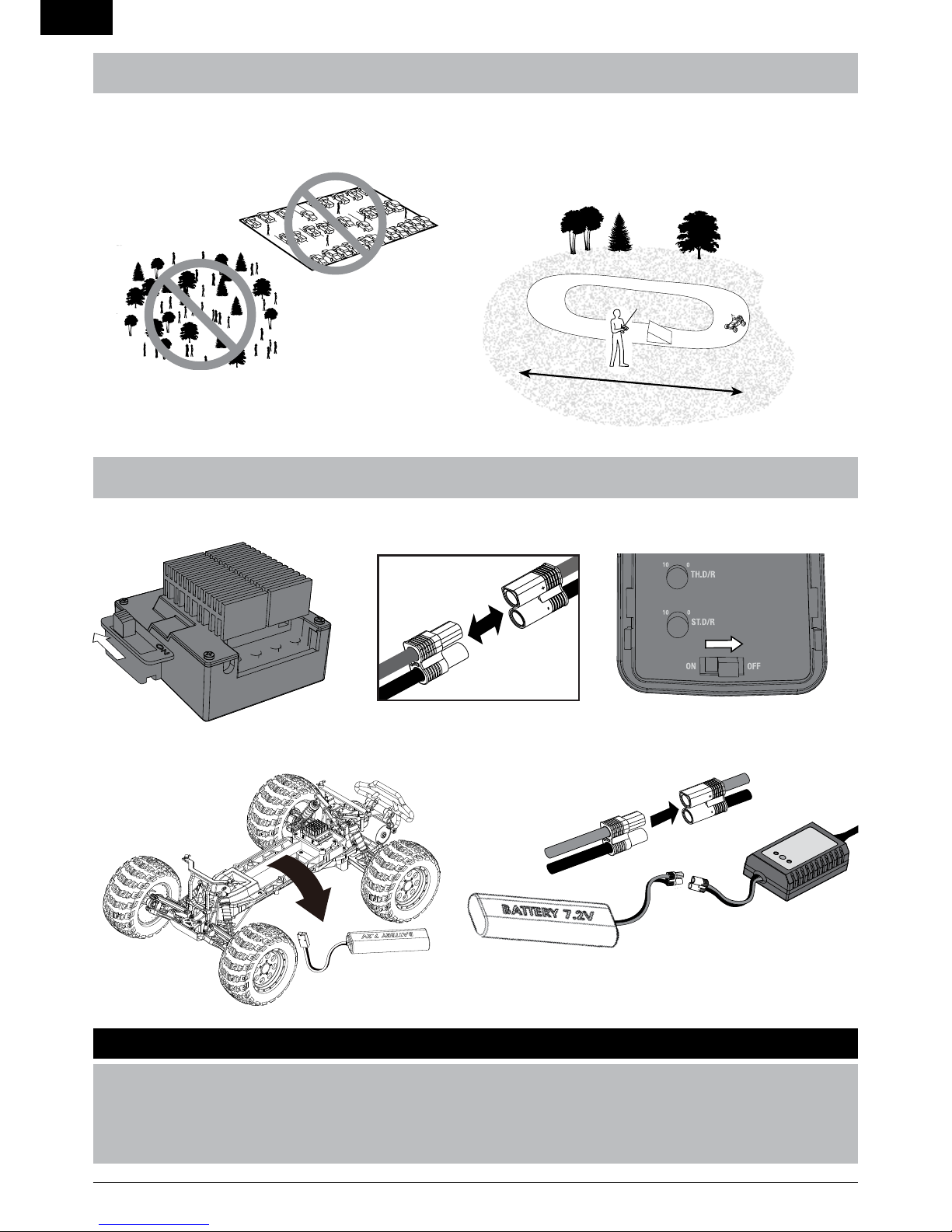
•Alwaysoperateyourmodelinanopenareaawayfromcars,
traffic or people.
•Neveroperatethemodelinthestreetorinpopulatedareas
for any reason.
•Carefullyfollowthedirectionsandwarningsforthisandany
optional support equipment (chargers, rechargeable battery
packs, etc.) you use.
•Keepallchemicals,smallpartsandanythingelectrical
out of the reach of children.
•Ifelectronicsarewaterproof,weneedtoshowthe
waterproof vehicle information in the front of the manual.
•Neverlickorplaceanyportionofthemodelinyourmouth
as it could cause serious injury or even death.
•Exercisecautionwhenusingtoolsandsharpinstruments.
•Takecareduringmaintenanceassomepartsmayhave
sharp edges.
•Immediatelyafterusingyourmodel,doNOTtouchequipment
such as the motor, electronic speed control and battery, because
they generate high temperatures. You may burn yourself seriously
touching them.
•Donotputfingersoranyobjectsinsiderotatingandmovingparts,
as this may cause damage or serious injury.
•Alwaysturnonyourtransmitterbeforeyouturnonthe
receiver in the car. Always turn off the receiver before
turning your transmitter off.
•Keepthewheelsofthemodeloffthegroundwhen
checking the operation of the radio equipment.
WARNING: Read the ENTIRE instruction manual to become familiar with the features of the product before operating.
Failure to operate the product correctly can result in damage to the product, personal property and cause serious injury.
ThisisasophisticatedhobbyproductandNOTatoy.Itmustbeoperatedwithcautionandcommonsenseandrequiressomebasicmechanical
ability. Failure to operate this Product in a safe and responsible manner could result in injury or damage to the product or other property. This
product is not intended for use by children without direct adult supervision. Do not attempt disassembly, use with incompatible components
or augment product in any way without the approval of Horizon Hobby, Inc. This manual contains instructions for safety, operation and
maintenance. It is essential to read and follow all the instructions and warnings in the manual, prior to assembly, setup or use,
in order to operate correctly and avoid damage or serious injury.
Age Recommendation: Not for children under 14 years. This is not a toy.
Meaning of Special Language:
The following terms are used throughout the product literature to indicate various levels of potential harm when operating this product:
NOTICE: Procedures, which if not properly followed, create a possibility of physical property damage AND little or no possibility of injury.
CAUTION: Procedures, which if not properly followed, create the probability of physical property damage AND a possibility of serious injury.
WARNING: Procedures, which if not properly followed, create the probability of property damage, collateral damage, and serious injury
ORcreateahighprobabilityofsupercialinjury.
Safety Precautions and Warnings .......................................................2
Water-Resistant Vehicle with Waterproof Electronics ............3
Specifications ...................................................................................4
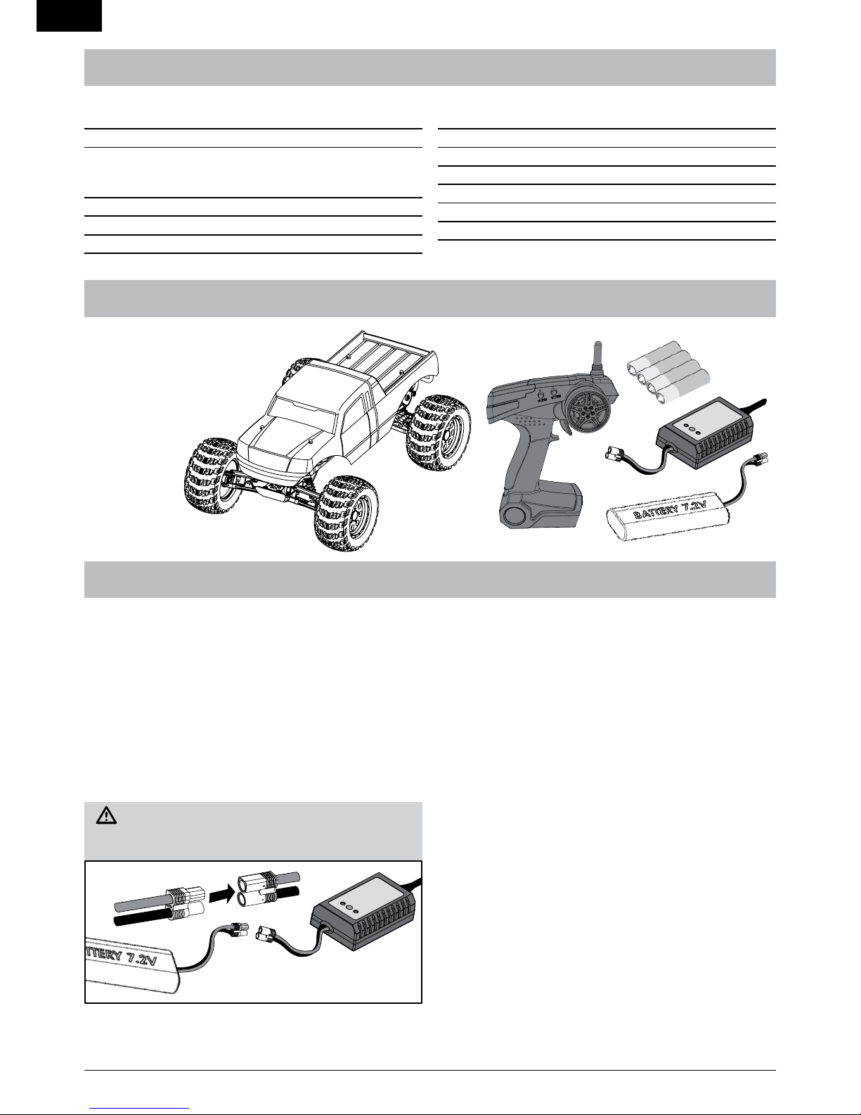
Components.......................................................................................4
Vehicle Preparations .......................................................................4
Charging the Vehicle Battery ...............................................................4
Charging Warnings and Precautions ...................................................4
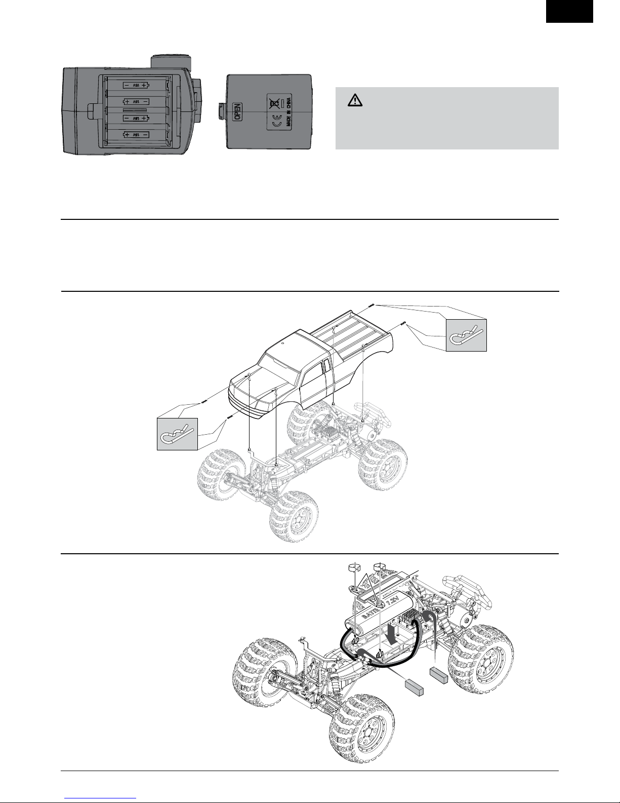
Installing Transmitter Batteries ...........................................................5
Installing the Vehicle Batteries............................................................5
Transmitter Battery Safety Precautions...............................................5
Removing the Vehicle Body .................................................................5
Installing the Battery in the Vehicle ....................................................5
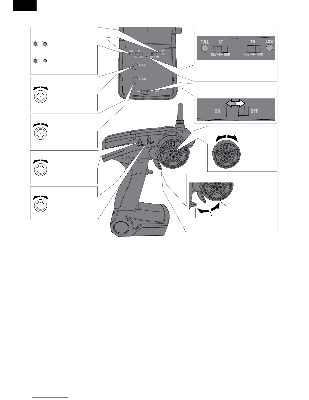
Transmitter controls.............................................................................6
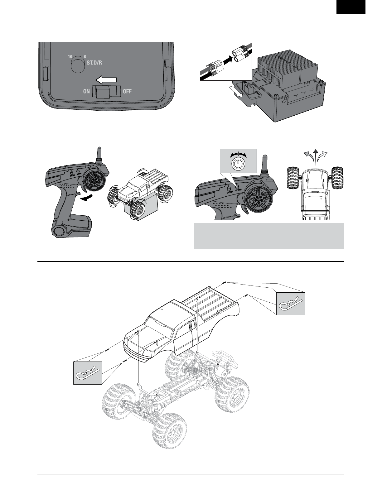
Getting Started.....................................................................................7
Installing the Vehicle Body ..................................................................7
Operation............................................................................................8
When you are Finished....................................................................8
Motor Care.........................................................................................8
Maintenance .....................................................................................9
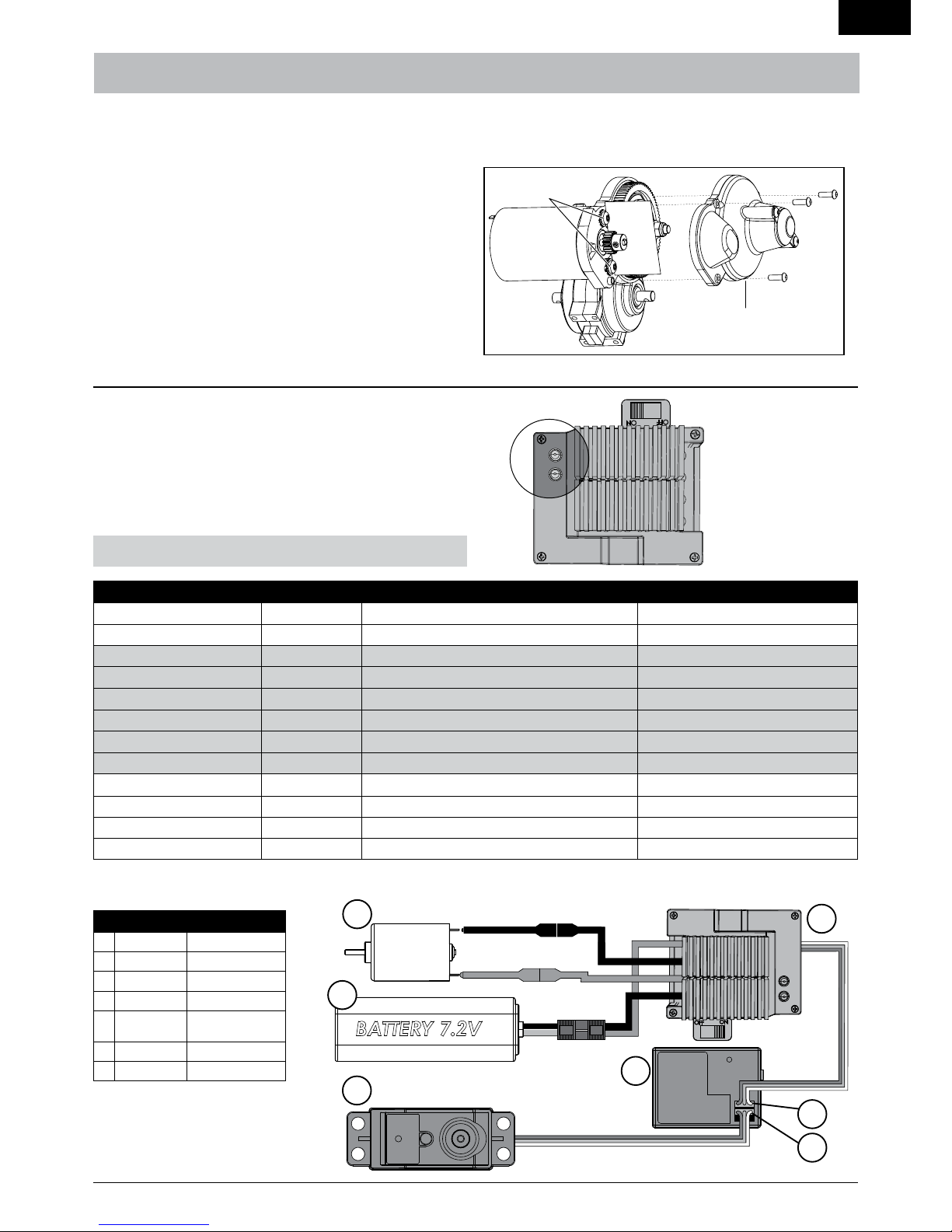
Setting the Gear Mesh.........................................................................9
Electronic Speed Control (ESC)............................................................9
Electrical Layout...................................................................................9
Shock Cleaning....................................................................................10
Fasteners.............................................................................................10
Binding ................................................................................................11
Troubleshooting Guide........................................................................11
Limited Warranty .............................................................................12
Contact Information ............................................................................13
FCC Information................................................................................13
Compliance Information for the European Union......................13
Parts Diagrams.................................................................................14
Parts Lists............................................................................................16
TABLE OF CONTENTS

3
EN
RUCKUS
WATER-RESISTANT VEHICLE WITH WATERPROOF ELECTRONICS
Your new Horizon Hobby vehicle has been designed and built with
a combination of waterproof and water-resistant components to
allow you to operate the product in many “wet conditions,”
including puddles, creeks, wet grass, snow and even rain.
While the entire vehicle is highly water-resistant, it is not completely
waterproofandyourvehicleshouldNOTbetreatedlikeasubmarine.
The various electronic components used in the vehicle, such as the
Electronic Speed Control (ESC), servo(s) and receiver are waterproof,
however, most of the mechanical components are water-resistant
and should not be submerged.
Metal parts, including the bearings, hinge pins, screws and nuts, as
well as the contacts in the electrical cables, will be susceptible to
corrosion if additional maintenance is not performed after running
inwetconditions.Tomaximizethelong-termperformanceofyour
vehicle and to keep the warranty intact, the procedures described in
the “Wet Conditions Maintenance” section below must be performed
regularly if you choose to run in wet conditions. If you are not willing
to perform the additional care and maintenance required, then you
should not operate the vehicle in those conditions.
CAUTION:Failuretoexercisecautionwhileusingthis
product and complying with the following precautions could
result in product malfunction and/or void the warranty.
General Precautions
•Readthroughthewetconditionsmaintenanceproceduresand
make sure that you have all the tools you will need to properly
maintain your vehicle.
•Notallbatteriescanbeusedinwetconditions.Consultthe
battery manufacturer before use. Do not use Li-Po batteries
in wet conditions.
•Mosttransmittersarenotwater-resistant.Consultyour
transmitter’s manual or the manufacturer before operation.
•Neveroperateyourtransmitterorvehiclewherelightning
may be present.
•Donotoperateyourvehiclewhereitcouldcomeincontact
with salt water (ocean water or water on salt-covered roads),
contaminated or polluted water. Salt water is very conductive
and highly corrosive, so use caution.
•Evenminimalwatercontactcanreducethelifeofyourmotorif
it has not been certified as water-resistant or waterproof. If the
motorbecomesexcessivelywet,applyverylightthrottleuntilthe
water is mostly removed from the motor. Running a wet motor at
high speeds may rapidly damage the motor.
•Drivinginwetconditionscanreducethelifeofthemotor.The
additionalresistanceofoperatinginwatercausesexcessstrain.
Alter the gear ratio by using a smaller pinion or larger spur gear.
This will increase torque (and motor life) when running in mud,
deeper puddles, or any wet conditions that will increase the
loadonthemotorforanextendedperiodoftime.
Wet Conditions Maintenance
•Removethebatterypack(s)anddrythecontacts.Ifyouhaveanair
compressor or a can of compressed air, blow out any water that
may be inside the recessed connector housing.
•Removethetires/wheelsfromthevehicleandgentlyrinsethe
mud and dirt off with a garden hose. Avoid rinsing the bearings
and transmission.
NOTICE: Never use a pressure washer to clean your vehicle.
•Useanaircompressororacanofcompressedairtodrythe
vehicle and help remove any water that may have gotten into
small crevices or corners.
•Spraythebearings,drivetrain,fastenersandothermetalparts
with WD-40® solvent or any other water-displacing light oil.
Do not spray the motor.
•Letthevehicleairdrybeforeyoustoreit.Water(andoil)may
continue to drip for a few hours.
•Increasethefrequencyofdisassembly,inspectionandlubrication
of the following:
•Frontandrearaxlehubassemblybearings.
•Alltransmissioncases,gearsanddifferentials.
•Motor—cleanwithanaerosolmotorcleanerand
re-oil the bushings with lightweight motor oil.

4
EN
RUCKUS
Transmitter
Frequency 2.4GHz
Battery AAx4
Servo
Power Supply 4.8V~6V (shared with receiver)
OutputTorque 41.66oz(3kg-cm)
OperatingSpeed 0.23sec/60degreesoftravel
Size 40.5x20x36.8mm
Electronic Speed Control (ESC)
Input Voltage 7.2–8.4V
Electric Capacity (FET) Forward 80 A/240 A
Electric Capacity (FET) Reverse 60 A/160 A
PWM Frequency 1kHz
BEC Voltage 5 V/1 A
Size 27x35x17.3mm
Weight 34–36 g
SPECIFICATIONS
COMPONENTS
VEHICLE PREPARATIONS
1
CHARGINGTHE VEHICLE BATTERY
1. Connect the AC power cord to the power slot on the charger, then
connect the other end of the power cord to an AC power source.
2. The Power LED and Charging LED will turn GREEN when the
charger is connected to the AC power source.
3. Connect the battery pack connector to the charge connector.
4.PresstheOn/Offbuttontochargethebattery.TheCharging
LED turns RED.
5. When the battery pack is fully charged, the Charging
LED will turn GREEN.
6.PresstheOn/Offbuttontostopcharging.Disconnect
the battery pack connector from the charge connector.
CAUTION: If at any time during the charge process the
battery pack(s) becomes hot to the touch, unplug the battery
immediately and discontinue the charge process.
The vehicle battery charger produces 2000 milliAmps (2 Amps) per
hour. Divide the mAh capacity on the label of a battery by 2000 to
knowhowlongbatterychargingwillrequire.Forexample,afully
discharged 1800mAh battery requires 0.9 hours (54 minutes) to charge.
1. ECX™Ruckus®1/10-scale Monster Truck
2. ECX™2.4GHz Transmitter
3. AA (4) Batteries
4. DYN4113 2A Peak Battery Charger
5. Dynamite®Speedpack™7.2V
Ni-MH battery (DYN1050EC)
2
5
3
4
CHARGING WARNINGS AND PRECAUTIONS
•Readallsafetyprecautionsandliteraturepriortouse
of this product.
•Neverallowminorstochargebatterypacks.
•Neverattempttochargedeadordamagedbatteries.
•Neverchargeabatteryifthecablehasbeenpinchedorshorted.
•Neverallowbatteriesorchargerstocomeintocontactwith
moisture at any time.
•Neverchargebatteriesinextremelyhotorcoldplaces
(recommended between 50–80°F or 10–26°C) or place
in direct sunlight.
•AlwaysuseonlyNi-MHrechargeablebatteries.Thischarger
cannot charge batteries such as “heavy duty,” “alkaline battery,”
or “mercury battery.”
•Alwaysconnectthepositiveredlead(+)andnegativeblacklead(-)
terminals of the battery to the charger terminals correctly.
•Alwaysdisconnectthebatteryandchargeraftercharging
and let them cool between charges.
•Alwaysinspectthebatterybeforecharging.
•AlwaysterminateallprocessesandcontactHorizonHobby
if the product malfunctions.
•Alwaysmakesureyouknowthespecificationsofthebattery
to be charged or discharged to ensure it meets the requirements
of this charger.
•Neverconnectmorethanonebatterypacktothischarger
at a time.
•Alwaysconstantlymonitorthetemperatureofthebattery
pack while charging.
•Alwaysendthechargingprocessifthechargerorbatterybecomes
hot to the touch or starts to change form during the charge process.

5
EN
RUCKUS
•Neverinstalldamagedbatteries.
•Neverinstallbatteriesofmixedtypes
or of different ages in the transmitter.
•Alwaysremoveexhaustedbatteries.
•Alwaysremovebatteriesbeforestoringthetransmitter.
•LowbatterypowercanresultinlossofcontroloftheRCvehicle.
TRANSMITTER BATTERY SAFETY PRECAUTIONS
REMOVINGTHE VEHICLE BODY
A B
INSTALLINGTHE BATTERY INTHE VEHICLE
1. Turn the battery clips (A) clockwise
to remove the battery strap (B).
2. Install a fully charged battery.
3. Install the battery strap.
4. Turn the battery clips counterclockwise
to secure the battery strap.
If desired, you can put foam blocks (ECX2015)
in front of the battery so the weight of the
battery increases rear traction or in back
of the battery to increase steering response.
INSTALLINGTRANSMITTER BATTERIES
Install 4 AA alkaline batteries into the transmitter,
following the instructions provided for your radio system.
We recommend using only alkaline AA batteries in the transmitter;
however, it is possible to use rechargeable Ni-MH batteries.
CAUTION: If using rechargeable batteries, charge
only rechargeable batteries. Charging non-rechargeable
batteries may cause the batteries to burst, resulting in
injury to persons and/or damage to property.
NEVERinstalldamagedbatteries,batteriesofmixedtypesorbatteries
ofdifferentagesinthetransmitter.Removeexhaustedbatteries.
NEVER store the transmitter with batteries installed.

6
EN
RUCKUS
TRANSMITTER CONTROLS
Battery Level Indicator
Solid Red and Green:
Battery voltage is
good (above 4V).
Solid Red: Battery
voltage is critically low
(below 4V). Replace
transmitter batteries.
Power Switch
Power on or off the transmitter
Steering Wheel
Control steering.
Right and Left
steering with
ST. REV Switch
on REV (See
Reverse Switch)
ThrottleTrigger
Controls power
to the motor for
forward or reverse
(See TH. REV
switch)
Stop
Reverse
(when TH.
REV switch on R)
Forward
(when TH.
REV switch on R)
Adjusts the neutral
point of the electronic
speed control
ThrottleTrim
Steering Rate
Adjusts the amount the
front wheels move when
the steering wheel is
turned left or right
Adjust to make the
vehicle drive straight
with no input at the
steering wheel
SteeringTrim
Reverse Switch
Allows you to change the direction of steering
(ST. REV) and throttle (TH. REV) controls. (The
default setting for steering and throttle is “REV.”)
Throttle Dual Rate
Adjuststhemaximum
amount throttle the
vehicle can be given

7
EN
RUCKUS
GETTING STARTED
1. Power on the transmitter.
3. Do a test of the transmitter’s control of the vehicle with
the vehicle’s wheels off the ground. 4. Start driving slowly, and, if the vehicle does not go straight,
adjust the steering trim dial on the transmitter.
NOTICE: Seat the motor brushes by driving smoothly on a flat
surfaceduringuseoftherstbatterycharge.Properlyseatingthe
motor brushes will increase the life and performance of the motor.
2. Power on the ESC.
INSTALLINGTHE VEHICLE BODY

8
EN
RUCKUS
•ALWAYSturnonyourtransmitterbeforeyouturnonthe
receiver in the vehicle. Always power off the receiver before
turning your transmitter off.
•ALWAYSoperateyourvehicleinawideopenarea.Operating
the vehicle in a small space or indoors can cause overheating
atlowspeeds.Operatingatlowspeedincreasesheatinthe
electronicspeedcontrol(ESC).Overheatingcandamage
the vehicle and failure may result.
OPERATION
WHENYOU ARE FINISHED
•Seatthemotorbrushesbydrivingsmoothlyonaflatsurface
during use of the first battery charge. Failing to do so can
greatly reduce motor performance and functional life.
•Prolongmotorlifebypreventingoverheatingconditions.
Unduemotorwearresultsfromfrequentturns,stopsand
starts, pushing objects, driving in deep water and tall grass,
and driving continuously up hill.
•Over-temperatureprotectionisinstalledontheESCtoprevent
circuit damage, but cannot protect the motor from driving against
heavy resistance.
MOTOR CARE
1. Power off the Electronic Speed Control (ESC). 2. Disconnect the battery.
4. Remove the battery from the vehicle.
3. Power off the transmitter.
5. Recharge the battery.

9
EN
RUCKUS
MAINTENANCE
ELECTRONIC SPEED CONTROL (ESC)
Low voltage cutoff (LVC) protects the battery from overdischarge by
activating when the battery reaches 1V per cell under load. The ESC
willresetafterapproximately10seconds.Thevehiclecanthenbe
driven slowly back to the driver for battery recharge.
Important: When the motor is disconnected or damaged,
the beep may not be heard.
NOTICE: Continually driving to LVC may damage the battery.
SETTINGTHE GEAR MESH
The gear mesh has already been set at the factory. Setting the gear
mesh is only necessary when changing motors or gears.
You must remove the vehicle’s gear cover (A) to make this adjustment.
Proper gear mesh (how the gear teeth meet) is important to the perfor-
mance of the vehicle. When the gear mesh is too loose, the spur gear
could be damaged by the pinion gear of the motor. If the mesh is too
tight, speed could be limited and the motor and ESC will overheat.
Set the gear mesh by following these simple steps:
1. Loosen the 2 motor screws (B).
2. Put a small piece of paper (C) between the pinion and spur gears.
3. Push the gears together while tightening the motor screws.
4. Rotate the gears to remove the paper. The gearing should
move a small amount.
5. Reinstall the gear cover.
A
C
B
ELECTRICAL LAYOUT
For correct operation, Channels 1
and 2 must be used as shown in the
wiring diagram. The motor can be
disconnected from the ESC at the
connectors in the wiring.
Part # Description
A ECX1072
Motor
B
DYN1050EC Battery 7.2V
C DYN3900
Steering Servo
D ECX9011
Receiver
E DYN4925WP
Electronic Speed
Control (ESC)
F
Channel 1
G
Channel 2
EC3EC3
A
B
CD
E
G
F
Operation LED Color LED Status Sound
NiMHPowerON Flashing Green ON
Li-PoPowerON Flashing Red ON
Stop Solid Green ON
Forward All OFF
Forward (full speed) Red ON
Reverse All OFF
Reverse (full speed) Green ON
Brake All Solid ON
Overheat All LEDs LEDs alternately flashing 1 beep per second
Motor Stalled Red LED Flashing quickly 3 times, stopping, then repeating 1 beep per second
BatteryOverVoltage(over10V) All LEDs Solid Red LED. Green LED flashing once per second 1 beep per second
BatteryUnderVoltage(5.0V) All LEDs Solid Green LED. Red LED flashing once per second 1 beep per 5 seconds

10
EN
RUCKUS
SHOCK CLEANING
Oil-lledshockswillrequireregularmaintenanceduetotheoil
breaking down or getting dirty. This maintenance should be performed
after about every 3 to 5 hours of use, depending on the conditions that
the vehicle is used in.
•Removetheshockfromthevehicle.
•Removethecapfromtheshockbodyanddisposeoffluid.
•Disassembletheshock.CleanthoroughlywithDYN5505.
Dry parts before assembly.
•Re-assembletheshockandrefilltheshockbodywithsilicone
fluid (30 weight recommended).
•Slowlymovetheshaftandpistonupanddowntoremove
air bubbles.
•Movethepistontothemidwaypointofthebodyand
install the cap.
•Wipeoffanyoverflowingfluid.
•Whenproperlyfilled,thepistonshouldreboundabout
3/8 in (9.5mm) after being pushed in fully.
•Re-installtheshockonthevehicle.
Ride Height Adjustment
Ride height is an adjustment that affects the way the vehicle
jumps, turns and goes over bumps. Drop one end of the vehicle from
approximately6inches(152mm)inheightontoaatsurface.When
dropping the front of the vehicle, after the vehicle settles, make
sure the front arms are equal and parallel to the flat surface. Do
the same with the rear to make sure both arms are parallel with
the flat surface.
Lowering the front ride height increases steering, but decreases
traction. Lowering the rear ride height increases traction, but
decreases steering.
Part # Description
ECX1036 Shock Body Set
ECX1037 Shock Caps, Pistons
ECX1038 Shock Parts Set
ECX1039 Front Shock Shaft (2)
ECX1040 Rear Shock Shaft (2)
ECX1041 Front Shock Springs (2)
ECX1042 Rear Shock Springs (2)
ECX1043 ShockO-RingSet
No. Description
TAPPING BINDER HEAD M3x10mm
TAPPING BINDER HEAD M3x12mm
TAPPING FLAT HEAD M3x15mm
TAPPING FLAT HEAD M3x12mm
TAPPING FLAT HEAD M3x10mm
TAPPING BINDER HEAD M3x18mm
TAPPING FLAT HEAD M2x16mm
TAPPING BINDER HEAD M3x16mm
No. Description
WASHER 5x7x0.5mm
E-CLIP E2.5
LOCK WASHER
FLANGED LOCK NUT M4
WASHER 3x8x0.5mm
LOCK NUT M3
WASHER 2x7x0.5mm
SET SHAFT SCREW M3x13mm
No. Description
BUTTON HEX M2.5x4mm
SETSCREW M3x3mm
SETSCREW M3x12mm
STEP SCREW M3x0.5x13.4mm
STEP SCREW M3x0.5x10.5mm
BUTTON HEX M2.5x8mm
STEP SCREW M3x0.5x7.4mm
No. Description
BINDER HEAD M3x8mm
BINDER HEAD M3x12mm
BINDER HEAD M3x20mm
BINDER HEAD M3x25mm
BUTTON HEAD M3x30mm
BUTTON HEAD M2x6mm
TAPPING BUTTON HEAD M3x10mm
REAR SHOCK FRONT SHOCK
Front Shock
ECX1043
ECX1037
ECX1037
ECX1041
ECX1037
ECX1043
Rear Shock
ECX1036
ECX1038
ECX1038
ECX1043
ECX1037
ECX1037
ECX1038
ECX1042
ECX1040
ECX1057
ECX1037
ECX1043
ECX1038
ECX1039
ECX1036
ECX1038
ECX1038
ECX1037
ECX1057
FASTENERS

11
EN
RUCKUS
BINDING
Failsafe
In the unlikely event the radio connection is lost during use, the
receiver will reduce the throttle to idle. The steering channel holds the
last input command. If you power on the receiver before powering on
the transmitter, the receiver enters failsafe mode with throttle at idle.
When you power on the transmitter, normal control resumes.
Binding is the process of programming the receiver of the control unit
torecognizetheGUID(GloballyUniqueIdentier)codeofasingle
specictransmitter.Theincludedtransmitterandreceiverarebound
at the factory. If you need to rebind, follow the instructions below.
1. Power off the transmitter and ESC.
2. Connect a fully charged battery pack to the ESC.
3. Power on the ESC.
4. Remove the front cover. Press the bind button (A) on
the receiver. The RED LED on the receiver flashes rapidly.
5. Power on the transmitter.
6. The RED LED on the receiver turns solid when
the system is bound. Replace the front cover.
You must rebind when you want to use
a different transmitter.
A
Problem Possible Cause Solution
Short Run Time •Batterydamaged/notcharged
•Motordirtyorbrushesworn
•Check/changebattery
•Check/clean/replace
Sluggish Action •Motordirtyorbrushesworn
•Bindindrivetrain
•Vehiclebatteryisnotcharged
•Check/clean/replace
•Clean/adjust
•Replace/recharge
Controls Reversed •ST.REVorTH.REV •Changeswitchposition
Motor/ESC overheat •Over-gearedforthedrivingenvironment •Installsmallerpinion
Doesn’tOperate •Transmitterbatterieslow
•Transmitterpoweredoff
•ESCpoweredoff
•Vehiclebatteryisnotcharged
•Replace/recharge
•PowerOn
•PowerOn
•Replace/recharge
Poor Range •Transmitterbatterieslow
•Transmitterantennaisdamagedorloose
•Receiverantennadamaged
•Replace/recharge
•Check/tighten
•Check/repair/replace
The system will not connect •Transmitterandreceivertooneareachother
•Transmitterandreceivertoonearlarge
metal objects (vehicles, etc.)
•Receiveraccidentallyputinbindmodeso
receiver is no longer bound
•Movetransmitter8–12feet(2.4–3.6m)fromreceiver
•Moveawayfromlargemetalobjects(vehicles,etc.)
•Rebindtransmitterandreceiver
The receiver goes into failsafe
mode a short distance away
from the transmitter
•Checkthereceiverantennatobesureitis
not cut or damaged
•ContactHorizonProductSupport
•Makesurereceiverantennaisinanantennatubeandisabovevehicle
The receiver quits responding
during operation
•Lowbatteryvoltage
•Looseordamagedwiresorconnectors
between battery and receiver
•Completelyrechargebattery
•Doacheckofthewiresandconnectionbetweenbatteryandreceiver.
Repair or replace wires and/or connectors
Receiver loses its bind •Transmitteraccidentallyputinbindmode,
ending bind to receiver
•Bindtransmittertoreceiver
TROUBLESHOOTING GUIDE

12
EN
RUCKUS
What this Warranty Covers
Horizon Hobby, Inc. (“Horizon”) warrants to the original purchaser
that the product purchased (the "Product") will be free from defects
in materials and workmanship at the date of purchase.
What is Not Covered
This warranty is not transferable and does not cover (i) cosmetic
damage, (ii) damage due to acts of God, accident, misuse, abuse,
negligence, commercial use, or due to improper use, installation,
operationormaintenance,(iii)modicationofortoanypartofthe
Product, (iv) attempted service by anyone other than a Horizon
Hobby authorized service center, (v) Product not purchased from an
authorized Horizon dealer, or (vi) Product not compliant with applicable
technical regulations.
OTHERTHANTHEEXPRESSWARRANTYABOVE,HORIZONMAKES
NOOTHERWARRANTYORREPRESENTATION,ANDHEREBY
DISCLAIMSANYANDALLIMPLIEDWARRANTIES,INCLUDING,
WITHOUTLIMITATION,THEIMPLIEDWARRANTIESOFNON-IN-
FRINGEMENT,MERCHANTABILITYANDFITNESSFORAPARTICULAR
PURPOSE.THEPURCHASERACKNOWLEDGESTHATTHEYALONE
HAVEDETERMINEDTHATTHEPRODUCTWILLSUITABLYMEET
THEREQUIREMENTSOFTHEPURCHASER’SINTENDEDUSE.
Purchaser’s Remedy
Horizon’ssoleobligationandpurchaser’ssoleandexclusiveremedy
shall be that Horizon will, at its option, either (i) service, or (ii) replace,
any Product determined by Horizon to be defective. Horizon reserves
the right to inspect any and all Product(s) involved in a warranty claim.
Service or replacement decisions are at the sole discretion of Horizon.
Proofofpurchaseisrequiredforallwarrantyclaims.SERVICEOR
REPLACEMENTASPROVIDEDUNDERTHISWARRANTYISTHEPUR-
CHASER’SSOLEANDEXCLUSIVEREMEDY.
Limitation of Liability
HORIZONSHALLNOTBELIABLEFORSPECIAL,INDIRECT,INCIDENTAL
ORCONSEQUENTIALDAMAGES,LOSSOFPROFITSORPRODUCTION
ORCOMMERCIALLOSSINANYWAY,REGARDLESSOFWHETHER
SUCHCLAIMISBASEDINCONTRACT,WARRANTY,TORT,NEGLI-
GENCE,STRICTLIABILITYORANYOTHERTHEORYOFLIABILITY,
EVENIFHORIZONHASBEENADVISEDOFTHEPOSSIBILITYOFSUCH
DAMAGES.Further,innoeventshalltheliabilityofHorizonexceed
the individual price of the Product on which liability is asserted. As
Horizonhasnocontroloveruse,setup,nalassembly,modication
or misuse, no liability shall be assumed nor accepted for any result-
ing damage or injury. By the act of use, setup or assembly, the user
accepts all resulting liability. If you as the purchaser or user are not
prepared to accept the liability associated with the use of the Product,
purchaser is advised to return the Product immediately in new and
unused condition to the place of purchase.
Law
These terms are governed by Illinois law (without regard to conflict
oflawprincipals).Thiswarrantygivesyouspeciclegalrights,
and you may also have other rights which vary from state to state.
Horizon reserves the right to change or modify this warranty at
any time without notice.
WARRANTY SERVICES
Questions, Assistance, and Repairs
Your local hobby store and/or place of purchase cannot provide war-
rantysupportorservice.Onceassembly,setuporuseoftheProduct
has been started, you must contact your local distributor or Horizon
directly. This will enable Horizon to better answer your questions and
service you in the event that you may need any assistance. For ques-
tions or assistance, please visit our website at www.horizonhobby.
com, submit a Product Support Inquiry, or call 877.504.0233 toll free to
speak to a Product Support representative.
Inspection or Services
If this Product needs to be inspected or serviced and is compliant in
the country you live and use the Product in, please use the Horizon
OnlineServiceRequestsubmissionprocessfoundonourwebsite
or call Horizon to obtain a Return Merchandise Authorization (RMA)
number. Pack the Product securely using a shipping carton. Please note
thatoriginalboxesmaybeincluded,butarenotdesignedtowithstand
the rigors of shipping without additional protection. Ship via a carrier
that provides tracking and insurance for lost or damaged parcels, as
Horizon is not responsible for merchandise until it arrives and is ac-
ceptedatourfacility.AnOnlineServiceRequestisavailableathttp://
www.horizonhobby.com/content/_service-center_render-service-
center. If you do not have internet access, please contact Horizon
Product Support to obtain a RMA number along with instructions for
submitting your product for service. When calling Horizon, you will be
asked to provide your complete name, street address, email address
and phone number where you can be reached during business hours.
When sending product into Horizon, please include your RMA number,
a list of the included items, and a brief summary of the problem. A
copy of your original sales receipt must be included for warranty con-
sideration. Be sure your name, address, and RMA number are clearly
written on the outside of the shipping carton.
NOTICE: Do not ship LiPo batteries to Horizon. If you
have any issue with a LiPo battery, please contact
the appropriate Horizon Product Support office.
Warranty Requirements
For Warranty consideration, you must include your original
sales receipt verifying the proof-of-purchase date. Provided
warranty conditions have been met, your Product will be serviced or
replaced free of charge. Service or replacement decisions are at the
sole discretion of Horizon.
Non-Warranty Repairs
Should your service not be covered by warranty, service will
be completed and payment will be required without notifica-
tion or estimate of the expense unless the expense exceeds
50% of the retail purchase cost. By submitting the item for service
youareagreeingtopaymentoftheservicewithoutnotication.
Service estimates are available upon request. You must include this
request with your item submitted for service. Non-warranty service
estimates will be billed a minimum of ½ hour of labor. In addition you
will be billed for return freight. Horizon accepts money orders and
cashier’schecks,aswellasVisa,MasterCard,AmericanExpress,and
Discover cards. By submitting any item to Horizon for service, you
are agreeing to Horizon’s Terms and Conditions found on our website
http://www.horizonhobby.com/content/_service-center_render-
service-center.
NOTICE: Horizon service is limited to Product compliant
in the country of use and ownership. If non-compliant
product is received by Horizon for service, it will be
returned unserviced at the sole expense of the purchaser.
LIMITED WARRANTY

13
EN
RUCKUS
Declaration of Conformity
(inaccordancewithISO/IEC17050-1)
No. HH2012081601
Product(s): ECX 1/10th Ruckus V2.0
ItemNumber(s): ECX2000SEU,ECX2100SEU
Equipment class: 1
The object of declaration described above is in conformity with
therequirementsofthespecicationslistedbelow,followingthe
provisions of the European R&TTE directive 1999/5/EC and EMC
Directive 2004/108/EC and LVD Directive 2006/95/EC:
EN 300-328 V1.7.1
EN 301 489-1 V1.7.1: 2006
EN 301 489-17 V1.3.2: 2008
EN 60950-1:2006+A12: 2011
EN55022: 2010
EN55024: 2010
EN61000-3-2:2006+A1:2009+A2:2009
EN61000-3-3:2008
Signed for and on behalf of:
Horizon Hobby, Inc.
Champaign,ILUSA
August 16, 2012
Instructions for disposal of WEEE
by users in the European Union
This product must not be disposed of with other waste.
Instead, it is the user’s responsibility to dispose of their waste
equipment by handing it over to a designated collections point
for the recycling of waste electrical and electronic equipment.
The separate collection and recycling of your waste equipment
at the time of disposal will help to conserve natural resources
and ensure that it is recycled in a manner that protects human
health and the environment. For more information about where
you can drop off your waste equipment for recycling, please
contactyourlocalcityofce,yourhouseholdwastedisposal
service or where you purchased the product.
Steven A. Hall
ExecutiveVicePresidentandChiefOperatingOfcer
InternationalOperationsandRiskManagement
Horizon Hobby, Inc.
CONTACT INFORMATION
Country of Purchase Horizon Hobby Address Phone Number/Email Address
UnitedStatesofAmerica Horizon Service Center
(Electronics and engines)
Horizon Product Support
4105 Fieldstone Rd
Champaign, Illinois
61822USA
877-504-0233
productsupport@horizonhobby.com
UnitedKingdom Horizon Hobby Limited Units1-4PloytersRd
Staple Tye
Harlow,Essex
CM18 7NS
UnitedKingdom
+44(0)1279641097
sales@horizonhobby.co.uk
Germany Horizon Technischer Service Christian-Junge-Straße 1
25337 Elmshorn
Germany
+49(0)41212655100
service@horizonhobby.de
France Horizon Hobby SAS 14 Rue Gustave Eiffel
Zoned’ActivitéduRéveilMatin
91230 Montgeron
+33(0)160474470
infofrance@horizonhobby.com
China Horizon Hobby - China Room 506, No. 97 Changshou Rd.
Shanghai, China 200060 +86(021)51809868
info@horizonhobby.com.cn
Thisdevicecomplieswithpart15oftheFCCrules.Operationis
subject to the following two conditions: (1) This device may not cause
harmful interference, and (2) this device must accept any interference
received, including interference that may cause undesired operation.
CAUTION:Changesormodicationsnotexpressly
approved by the party responsible for compliance could
void the user’s authority to operate the equipment.
This product contains a radio transmitter with wireless technology
which has been tested and found to be compliant with the applicable
regulations governing a radio transmitter in the 2.400GHz to
2.4835GHz frequency range.
FCC INFORMATION
COMPLIANCE INFORMATION FORTHE EUROPEAN UNION

14
EN
RUCKUS
M3X20
M3X12
M3x12
M3x15
M3X15
M3X10
M3X12
M3X12
M3X12
M3X12
M3X12
M3X12
M3X18
M3X10
M3X12
M3X15
M3x12
M3x15
M3x15
M3x25
M3X12
M3X10
M3X10
M3X10
M3X12
M3X25
M3X12
M3X12
M3X10
M3X10
M3X12
M3X15
M3X12
M3X12
M3X10
M3X8
M3X10
M3X12
M3X12
M3X3
M2.5X8
M2.5X8
M2.5X4
M3X12
M3X12
M3X18
32 32
6
36 25 3538 33
39 39
22 3434 34
34 34
15
36
42
15331548 3548
1515
33
33
41
33 33 35 33 35 33
36
38 25
M2X16
M2X16
35
12
44
46
25
47
43
43
17
43
43
11
13
13
12
46
12
25
47
3
19
19
28
21
30
13
14
26
31
31
15
15
27 13
20
21
23
7
13
14
15
15
30
8
18
8
20
19
16
2
2
2
72
13
20
31
31
7
20
20
1
5
9
12
22
44
45
12
12
17
13
46
19
7
2
8
8
7
2
2
2
19
10
311
45
29
22
40 33
28
24
20
20
50
39
4
49
28
PARTS DIAGRAM | EXPLOSIONSZEICHNUNG | VUE ÉCLATÉE DES
PIÈCES | ESPLOSO DEL MODELLO CON REFERENZA PEZZI
RECOMMENDED ITEMS
EMPFOHLENE WERKZEUGE
OUTILS RECOMMANDÉS
ATTREZZI CONSIGLIATI

15
EN
RUCKUS
M3X20
M3X12
M3x12
M3x15
M3X15
M3X10
M3X12
M3X12
M3X12
M3X12
M3X12
M3X12
M3X18
M3X10
M3X12
M3X15
M3x12
M3x15
M3x15
M3x25
M3X12
M3X10
M3X10
M3X10
M3X12
M3X25
M3X12
M3X12
M3X10
M3X10
M3X12
M3X15
M3X12
M3X12
M3X10
M3X8
M3X10
M3X12
M3X12
M3X3
M2.5X8
M2.5X8
M2.5X4
M3X12
M3X12
M3X18
32 32
6
36 25 3538 33
39 39
22 3434 34
34 34
15
36
42
15331548 3548
1515
33
33
41
33 33 35 33 35 33
36
38 25
M2X16
M2X16
35
12
44
46
25
47
43
43
17
43
43
11
13
13
12
46
12
25
47
3
19
19
28
21
30
13
14
26
31
31
15
15
27 13
20
21
23
7
13
14
15
15
30
8
18
8
20
19
16
2
2
2
72
13
20
31
31
7
20
20
1
5
9
12
22
44
45
12
12
17
13
46
19
7
2
8
8
7
2
2
2
19
10
311
45
29
22
40 33
28
24
20
20
50
39
4
49
28
Wheninstallingthewheel,makesurethedrivehexisalignedwiththedrivepin.
Whenthedrivehexisremoved,thedrivepincanfalloutoftheaxle.
Bitte achten Sie bei der Radmontage darauf, dass die Radachse im Radmitnehmer sitzt und
dass der der Querstift nicht heraus fällt.
Lorsdel’installationdelaroue,assurez-vousquel'hexagonederoueestalignéaveclagoupille
d'entraînement.Encasdedémontagedel'hexagone,lagoupillepeutsortirdel'axeettomber.
Quando montate le ruote, accertatevi che il trascinatore esagonale sia allineato con la spina
delmozzoruota.Quandotoglieteiltrascinatoreesagonalelaspinapuòslarsidalmozzo.
PARTS DIAGRAM | EXPLOSIONSZEICHNUNG | VUE ÉCLATÉE DES
PIÈCES | ESPLOSO DEL MODELLO CON REFERENZA PEZZI
The slipper clutch can be adjusted
using this locknut (ECX1060). Fully
tighten the locknut. Then loosen
the nut two full turns.
Die Rutschkupplung kann durch
diese Stopmutter eingestellt
werden(ECX1060).ZiehenSiedie
Mutter an und drehen Sie dann
vollezweiUmdrehungenzurück.
Il est possible d’ajuster le
sliper par action sur cet écrou
de blocage (ECX1060). Veillez à
serrer l’écrou de blocage à fond.
Ensuite, devissez l’écrou de
trois tours complets.
La frizione può essere regolata
con questo dado autobloccante
(ECX1060). Prima avvitate comple-
tamente il dado, poi svitatelo 2 giri.

16
EN
RUCKUS
Replacement Parts / Ersatzteile / Pièces de rechange / Pezzi di ricambio
Part # | Nummer
Numéro | Codice Description Beschreibung Description Descrizione
DYN4113
2A Peak Charger 2A Peak Ni-MH Ladegerät 2A Chargeur à détection
de pics 2A Caricabatterie a rileva-
mento di picchi
DYN1050EC
Ni-MH battery Ni-MH akku Batterie Ni-MH Batteria Ni-MH
1
ECX2008 Main Chassis
Chassis Châssis principal Telaio principale
2
ECX1028 Servo Saver Set
Servo Saver Set Jeu de sauvegarde de servo Set salvaservo
3
ECX2011
Cover and Rear Mount Set Abdeckung und hinterer Halter
Set Capotetxationsarrières Copertura e set di montaggio
posteriore
4
ECX1050 SetscrewM3x12(4)
SchraubenSetM3x12(4) JeudevisM3x12(4) GraniM3x12(4)
5
ECX2015 Foam Block
Schaum Block Bloc de mousse Spugna distanziale batteria
6
ECX1052
Motor Screw/Washer Set Motor Screw/Washer Set
Vis Moteur/Set Rondelles Viti per il motore/ set di rondelle
7
ECX1058 Ball Stud (6)
Kugelkopf (6) Rondelle (6) SfereUniball(6)
8
ECX1065 Shoulder Screw Set (8)
Passschrauben Set (8) Jeu de vis d’épaulement (8) Set viti a doppio stadio (8)
9 ECX9011
Receiver
Empfänger Récepteur Ricevente
10 DYN3900
Servo
Servo Servo
Servo
11
ECX1088 Battery Hold Down
Akkuhalter Fixationpourbatterie Piastra fermabatteria
12
ECX2012 Front/Rear Bumper Set
Stoßstange vorne hinten Jeu de pare-chocs avant/arrière Set paraurti ant/post
13 ECX2006
Suspension Arm Mount Set Querlenker Set hinten Jeu de renfort de suspension Supporti braccetti sosp.
14
ECX2204 Mounted Wheel/Tire (2),
Black Rad montiert (2), Schwarz Roue Montée/Pneu (2) , Noire Ruote e gomme montate (2) , Nero
15
ECX1015 Wheel Bearing Set
Radlagersatz Set Jeu de roulement de roue Set cuscinetti ruote
16
ECX1018 Front Suspension Arm Set
Querlenker Set vorne Jeu de bras de suspension avant Braccetti delle sospensioni
anteriori
17
ECX1020 Shock Tower Set
Dämpferbrücke Jeu de support d’amortisseur Supporto ammortizzatori posteriori
18
ECX1035 FrontAxle(2)
Radachse vorne (2) Axeavant(2) Mozzi ruota anteriori (2)
19
ECX1044 Hinge Pin Set
Querlenkerbolzen Set Jeudebroched’axe Set perni sospensioni
20
ECX1046 Camber, Toe Link Set
Spur- Sturzstangenset Jeu de biellette de cambrure,
de pincement Set tiranteria Camber
e convergenza
21
ECX1049 Wheel Pins (4)
Radmitnehmerstifte (4) Broches de roue (4) Spine trascinatori ruote (4)
22
ECX1060 M4 Locknut (4)
M4 Stopmutter (4) Ecrou de blocage M4 (4) Dadi autobloccanti M4 (4)
23
ECX1089 Steering Block Set
Lenkhebel Set Jeu de bloc de direction Fuselli sterzo
24
ECX1019 Rear Suspension Arm Set
Querlenker Set hinten Jeu de bras de suspension arrière Braccetti delle sospensioni
posteriori
25
ECX1021 Transmission Case Set
Getriebegehäuse Ensemble carter de transmission Set scatola trasmissione
26
ECX230000
Driveshaft Set
Antriebswellen Set Ensemble arbre de transmission Set semiassi
27
ECX230001
RearAxle(2)
Wellenmitnehmer hinten (2) Axearrière(2) Mozzi ruota anteriori (2)
28
ECX1045 Hinge Pin Screws (8)
Querlenkerbolzen Schrauben (8) Visdebroched’axe(8) Viti per perni sospensioni (8)
29 DYN4925WP
ESC Regler / ESC CEV Variatore elettronico (ESC)
30 ECX1090
Rear Hub Carrier Set
Hinterer Rad Träger Set Jeu de porte-moyeu arrière Portamozzi posteriori
31
ECX1037
Shock Caps, Pistons Stoßdmämpferkappen Kolben Obturateursd’amortisseur,pistons Set tappi e pistoni ammortizzatori
32 ECX1027
Gear Cover Gear Cover Carter de Réducteur Copertura per ingranaggi
33
ECX1022 Transmission Gear Set
Getriebe Ensemble couronne de
transmission et ingranaggi trasmissione
34
ECX1024 Slipper Clutch Plates, Pads,
Spring
Rutschkupplung Teilesatz Plateauxd’embrayagepatinant,
plaquettes, ressort Piattelli frizione, disco, molla
35
ECX1025 Transmission Idler Shaft,
Drive Pins
Hauptgetriebewelle Set Arbre secondaire de transm-ission,
axesd’entraînement
Alberino intermedio con spina
36
ECX1026 Transmission Drive Shaft (2)
Getreibeausgangswelle (2) Axed’arbredetransmission(2) Mozzi Differenziale (2)
37
ECX1052 Washer Set
UnterlegscheibenSet Jeu de rondelles Set rondelle
38
ECX1055 Bearings10x15x4(2)
Lager10x15x4(2) Roulements10x15x4(2) Cuscinetti10x15x4(2)
39
ECX1059 M3 Locknut (4)
M3 Stopmutter (4) Ecrou de blocage M3 (4) Dadi autobloccanti M3 (4)
40
ECX1076 Spur Gear
Hauptzahnrad Couronne Corona
41 ECX1073
19-Tooth Pinion Gear 19-Tooth Pinion Gear Pignon 10 dents Pignone a 19 denti
42 DYN1172
Motor Motor Moteur Motore
43 ECX1048
Body Clip Body Clip Clips Carrosserie Clippe per carrozzeria
44 ECX2010
Body Post Set Body Post Set Set Plots Carrosserie Set di sostegni per la carrozzeria
45 ECX2009
Body Mount Set Body Mount Set Set Montage Carrosserie Set di montaggio per la carrozzeria
46 ECX2007
Skid Plate Set Skid Plate Set Set Plaque Chassis Set pistre di protezione
47 ECX2013
Rear Holder Set Rear Holder Set Set de Maintien Arrière Set supporto posteriore
48 ECX1023
Top Shaft/Spacer Top Shaft/Spacer Set de Goupilles Set di spessori
49 ECX1033
SetscrewM3x10
Sicherungsschrauben (4) Vis (4) Viti (4)
ECX2201
Printed Body, Green/Black Karosserie bedruckt Grün/
Schwarz Carrosserie décorée, vert/noir Carrozzeria stampata, verde/nero
ECX2202
Printed Body, Metal/Silver Karosserie bedruckt Gun
Metal/Silber Carrosserie décorée,
Métal/argent Carrozzeria stampata, metallo/
argento
ECX9010
Transmitter Sender Émetteur Trasmettitore
Optional Parts / DiverseTeile / Pièces optionnelles / Componenti opzionali
ECX2801
Body, Clear Karosserie unlackiert Carrosserie transparente Carrozzeria, trasparente
ECX2802
Wheels, Black Felgensatz Schwarz Jantes noires Ruote, nere

33334
Created 7/2012
© 2012 Horizon Hobby, Inc.
ECX, Ruckus, Dynamite and Speedpack are trademarks or registered trademarks
of Horizon Hobby, Inc. WD-40 is a registered trademark of WD-40 Manufacturing Company.
ECX2000S | ECX2000SA | ECX2000SEU
ECX2100S | ECX2100SA | ECX2100SEU
www.ecxrc.com
This manual suits for next models
5
Table of contents
Other ECX Motorized Toy Car manuals

ECX
ECX ECX00012T1 User manual

ECX
ECX TORMENT ECX03026 User manual

ECX
ECX TORMENT 03008 User manual

ECX
ECX ECX03131T1 User manual

ECX
ECX Ruckus ECX03002 User manual

ECX
ECX TORMENT ECX01001 User manual

ECX
ECX Torment ECX4000S User manual

ECX
ECX ECX1000S User manual

ECX
ECX BARRAGE ECX01011 User manual

ECX
ECX ECX03130T1 User manual

ECX
ECX RUCKUS TORMENT User manual

ECX
ECX Torment ECX4000S User manual

ECX
ECX Torment ECX03033T1 User manual

ECX
ECX BOOST ECX03032T1 User manual

ECX
ECX Boost ECX03004 User manual

ECX
ECX ECX00013T1 User manual

ECX
ECX Revenge E User manual

ECX
ECX BARRAGE ECX00017T1 User manual

ECX
ECX ROOST 01005T1 User manual

ECX
ECX Circuit ECX03030T1 User manual