manuals.online logo
Brands
  1. Home
  2. •
  3. Brands
  4. •
  5. Edelbrock
  6. •
  7. Automobile Part
  8. •
  9. Edelbrock 6661 User manual

Edelbrock 6661 User manual

2. Remove O2 sensor, being careful not to rupture or
destroy the unit.
W ARNING: Do not clean this unit in any cleaning solvent
and do not rupture wire.
3. Making sure the converter is cool, remove the exhaust
crossover pipe. You may find it helpful to clamp the con -
verter to the crossmember using pieces of wood and C-
clamps.This will allow you to work the crossover pipe
loose from the converter more easily. If the pipe is frozen
to the converter, it can be heated with a Propane torch
(or equivalent) to help loosen the joint.
4. Unbolt air conditioning support bracket on frame and use
a crescent wrench to bend bracket end approximately 5
to move hoses away from exhaust manifold (see Figure
1).
ASSEMBLY - LEFT SIDE
1.Install T.E.S. flange gasket and one 3/8"-16 x 1" bolt, lock
washer, and flat washer at rearmost bolt hole (leave bolt
loose enough to accept T.E.S.).
2.Installleftside T.E.S. manifold from bottom side.
3.Installallbolts and washers on left side and tighten.
4. Replace original equipment spark plug ends on cylinders
#5 and #7 with 60 connectors and boots provided in kit.
DISASSEMBLY - LEFT SIDE
1. Disconnect negative cable from battery.
2. Use penetrating oil on all nuts and bolts to be removed.
This will prevent the possibility of broken or stripped nuts
and bolts.
3. Remove air cleaner system (note position of line and
hose connections).
4. Disconnect A.I.R. (air injection reactor) tube from exhaust
manifold (if applicable).
5. Disconnect spark plug wires.
6. Disconnect temperature sensor wire.
7. Remove bolts and exhaust manifold.
DISASSEMBLY - RIGHT SIDE
1. Remove air cleaner box.
2. Remove air conditioning hose bracket under air cleaner
box (if applicable).
3. Disconnect spark plug wires.
4. Remove dipstick and both sections of dipstick tube.
5. Remove bolts and exhaust manifold .
6. Clean exhaust flange surfaces on cylinder heads at this
time.
7. Drill two 7/32" holes in the inner fender well p anel and pull
heater hoses to panel and secure with clamps provided.
DISASSEMBLY - CROSSOVER PIPE
1. Raise vehicle and support with jackstands.
' 1998 Edelbrock Corp. Rev 4/98
STAINLESS STEEL TUBULAR EXHAUST SYSTEM #6661
Application: 1992-’95 Chevrolet & GMC Suburban; 2500 Series, 2 & 4 W.D.,
7.4L V8 w/T.B.I., automatic & st d. transmission, w/o A.I.R.
INSTRUCTIONS
PLEASE study these instructions carefully before installing your new Tubular Exhaust System (T.E.S.). If you have any
questions or problems, do not hesitate to cont act our Technical Hotline at : 1-800-416-8628.
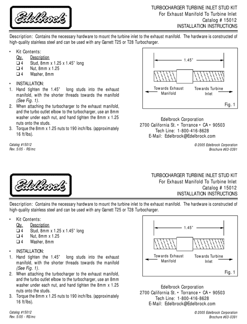
TUBULAR EXHAUST SYSTEM: These components are designed as a system to improve the exhaust efficiency of the
GM 7.4 Liter T.B.I. (Throttle Body Injection) V8 engine. They are constructed of 409 HP st ainless steel to better withst and
the high heat present with the T.B.I. engine, especially when used for towing or other heavy duty applications. The stain-
less steel used for these systems is much more durable than mild steel, although it does not appear different in appear-
ance. These systems come with a coat of black paint for good looks and protection during shipping and storage, and
they can be identified by the part numbers on each of the major components. Note that a magnet will stick to this type of
stainless steel; magnetic attraction is not a valid test for these systems. A performance gain can be expected by the
inst allation of the system. This system requires no welding for installation and ret ains all O.E.M. emissions equipment.
SUGGESTED TOOLS FOR INSTALLATION: This vehicle has some metric fasteners.
3/8 ratchet socket set with extensions and universal 13mm and 15mm swivel sockets
Combination set of open-end wrenches
Jackstands, screwdrivers, pliers, crescent wrench, etc.
Drill motor and 7/32" drill bit
Liquid penetrant, (GM #1052627) anti-seize compound (GM #5613695)
W ARNING: The use of Thermal Wrap materials will void the warranty on your Tubular Exhaust System. Those products
can cause excessive heat and moisture buildup resulting in corrosion of the system.
SPECIAL NOTICE: This Edelbrock part has received an Executive Order number (E.O. #) from the California Air
Resources Board (C.A.R.B.) making it legal for street use on pollution-controlled motor vehicles in all 50 states. To assist
you with emissions equipment certification, we have included a silver fan shroud decal to help testing personnel verify
that this p art is a legal replacement part on the vehicle for which it is cat aloged. The adhesive-backed decal should be
affixed to your fan shroud next to the existing emission and engine specification decal. Do not cover your original equip-
ment specification decal with the Edelbrock fan shroud decal.
NOTE: High temperature spark plug wires and boots are recommended to withstand heat from TES.
5. Re-connect spark plug wires on left side.
6. Re-install temperature sensor wire to temperature sensor.
ASSEMBLY - RIGHT SIDE
1.Install T.E.S. flange gasket and one 3/8"-16 x 1" bolt, lock
washer and flat washer at rearmost bolt hole (leave bolt
loose enough to accept T.E.S.).
2.Installdip stick tube and right side T.E.S. manifold from top
side.
3.Inst all remaining bolt s and lock washers. Use original
equipment stud-bolt to re-attach dip stick bracket.
4. Align all p art s and tighten all right side bolt s at this time.
5. Replace original equipment spark plug ends on cylinders
#4, #6 and #8 with 60 connectors and boots provided in
kit.
6. Re-connect right side spark plug wires.
7. Discard O.E.M. heat stove pipe and replace with flexible
tubing supplied (if applicable).
8. To prevent contact with the hot T.E.S. tubing, use nylon tie
wrap (supplied) to secure the heater hose to the a.c.
dryer.
PLEASE complete and mail your warranty card. Be sure to write the model number (#6661) in the Part #____ space.
THANK YOU.
Figure 1
Bend air conditioning support bracket approximately 5 using crescent wrench. Be sure that there is adequate clearance
between the hose’s aluminum tubing and right side inner fender panel af ter support bracket is bent.
CROSSOVER PIPE ASSEMBLY
1. Slip crossover pipe into Y-pipe assembly and extension
tube onto Y-pipe assembly outlet (do not clamp).
2. Place donut gaskets on extensions and slip tube into
mufflerinlet. Align p art s and start flange bolt s.
3. Check alignment of all parts then secure bolt s.
4.Install U-clamps and tighten all nut s and bolt s.
5. Re-inst all O2 sensor. Use anti-seize on threads of sensor
and torque to 30 ft./lbs. Re-route O2 sensor wire from
wire loom to O2 sensor making sure all wires are clear of
exhaust system (O2 sensor extension wire is included in
kit).
6. Lower vehicle to the ground.
CAUTION: Before operating you vehicle, check to
ensure that there is adequate clearance between all
part s of your TES (including A.I.R. tubes) and all brake
lines, fuel lines, sp ark plug wires, etc.
HARDWARE SUPPLIED
1- Manifold lef t side #25-9057
1- Manifold right side #25-9096
1- Extension pipe right side #25-
9563
1- Extension pipe left side #25-9562
1- Muffler extension #25-9564
4- Flat washers, 3/8"
16- Hex header bolts, 3/8"-16 x 1"
1- Flange connector
1- U-clamp, 2-1/2"
1- U-clamp, 3"
2- Chevy V8 port gaskets
2- Donut gaskets, 2-1/2"
1- Flex tubing, heat stove to air
cleaner
4- Hex bolt, 3/8"-16 x 2"
20- Lock washers, 3/8"
2- Tie wraps, 10"
1- Bolt 3/8-16 x 1-3/4"
1- S pacer tube 5/8 x .724"
2- Band-clamps
2- Hex nuts, 10-32
2- Hex cap screws, 10-32 x 1"
5- S park plug boots
5- Spark plug boot ends
2-Star washers; 3/16"

Other Edelbrock Automobile Part manuals

Edelbrock 29575 User manual

Edelbrock

Edelbrock 29575 User manual

Edelbrock 65232 User manual

Edelbrock

Edelbrock 65232 User manual

Edelbrock 6879 User manual

Edelbrock

Edelbrock 6879 User manual

Edelbrock Russell 641540 User manual

Edelbrock

Edelbrock Russell 641540 User manual

Edelbrock Russell 694540 User manual

Edelbrock

Edelbrock Russell 694540 User manual

Edelbrock 5645 User manual

Edelbrock

Edelbrock 5645 User manual

Edelbrock 7111 User manual

Edelbrock

Edelbrock 7111 User manual

Edelbrock VICTOR 8841 Instruction manual

Edelbrock

Edelbrock VICTOR 8841 Instruction manual

Edelbrock 71836 User manual

Edelbrock

Edelbrock 71836 User manual

Edelbrock 71001 User manual

Edelbrock

Edelbrock 71001 User manual

Edelbrock PERFORMER-PLUS 2167 User manual

Edelbrock

Edelbrock PERFORMER-PLUS 2167 User manual

Edelbrock 25-9492 User manual

Edelbrock

Edelbrock 25-9492 User manual

Edelbrock 4790 User manual

Edelbrock

Edelbrock 4790 User manual

Edelbrock 1795 User manual

Edelbrock

Edelbrock 1795 User manual

Edelbrock 8135 User manual

Edelbrock

Edelbrock 8135 User manual

Edelbrock QwikData 91001 User manual

Edelbrock

Edelbrock QwikData 91001 User manual

Edelbrock 5769 User manual

Edelbrock

Edelbrock 5769 User manual

Edelbrock 2121 User manual

Edelbrock

Edelbrock 2121 User manual

Edelbrock Performer 70070 User manual

Edelbrock

Edelbrock Performer 70070 User manual

Edelbrock 3638 User manual

Edelbrock

Edelbrock 3638 User manual

Edelbrock 77509 User manual

Edelbrock

Edelbrock 77509 User manual

Edelbrock 5788 User manual

Edelbrock

Edelbrock 5788 User manual

Edelbrock 2801 User manual

Edelbrock

Edelbrock 2801 User manual

Edelbrock 4254 User manual

Edelbrock

Edelbrock 4254 User manual

Popular Automobile Part manuals by other brands

Alphasonik PCP15LDE owner's manual

Alphasonik

Alphasonik PCP15LDE owner's manual

BENDIX A-18 TRAILER ABS manual

BENDIX

BENDIX A-18 TRAILER ABS manual

Art G 463 installation manual

Art

Art G 463 installation manual

Accel 140025 installation instructions

Accel

Accel 140025 installation instructions

Airaid 400-941 installation instructions

Airaid

Airaid 400-941 installation instructions

Landoll 930E Operator's manual

Landoll

Landoll 930E Operator's manual

TTE PZ439-C0181-00 installation manual

TTE

TTE PZ439-C0181-00 installation manual

AUTOTECH 10.425.1125GK-1125K installation instructions

AUTOTECH

AUTOTECH 10.425.1125GK-1125K installation instructions

Evinrude Speedometer/Depth Sounder owner's manual

Evinrude

Evinrude Speedometer/Depth Sounder owner's manual

Snapper 63178 parts manual

Snapper

Snapper 63178 parts manual

Atwood MPD 87850 Installation and operation manual

Atwood

Atwood MPD 87850 Installation and operation manual

Toyota PW405-05000 installation instructions

Toyota

Toyota PW405-05000 installation instructions

SAF-HOLLAND B9 Maintenance Instruction

SAF-HOLLAND

SAF-HOLLAND B9 Maintenance Instruction

Murphy Digital Time Meters HD35-CD product manual

Murphy

Murphy Digital Time Meters HD35-CD product manual

AUTOTECH 10.202.3012K 3022K installation instructions

AUTOTECH

AUTOTECH 10.202.3012K 3022K installation instructions

Vetus Uniflex 12 installation instructions

Vetus

Vetus Uniflex 12 installation instructions

Warn 61854 installation instructions

Warn

Warn 61854 installation instructions

SPL TRE Z34 installation instructions

SPL

SPL TRE Z34 installation instructions

manuals.online logo
manuals.online logoBrands
  • About & Mission
  • Contact us
  • Privacy Policy
  • Terms and Conditions

Copyright 2025 Manuals.Online. All Rights Reserved.