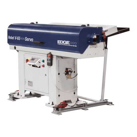
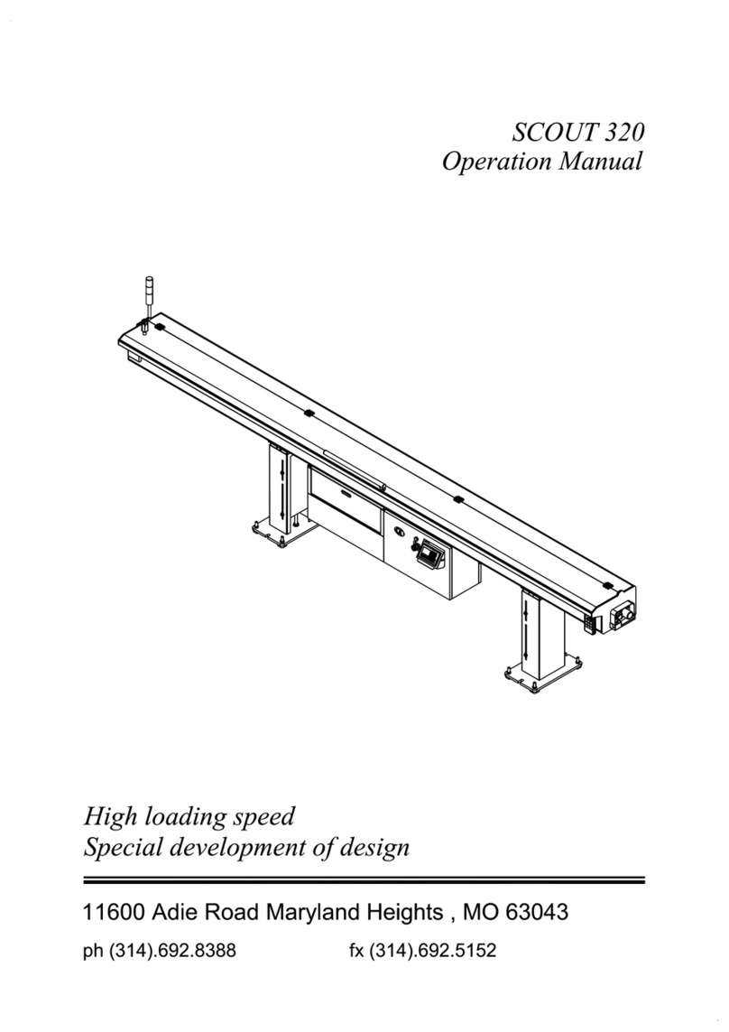
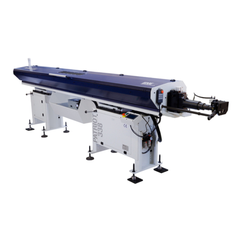
Edge Technologies Minuteman 320 SE User manual

Minuteman 320 SE
OPERATIONS MANUALOPERATIONS MANUAL
Version 13.1

MINUTEMAN320
HYDRODYNAMICAUTOMATICBARFEEDER
MM-320
MANUALFOR USEAND MAINTENANCE
REV. 13.1 DATE 2020/07/08 COD BMM103032
S/H

MINUTEMAN 320
i
Table of Contents
Section Page
1. General Information
1.1 Contents of this Manual ……………………………………………………… 1
1.2 Machine Safety ………………………………………………………………. 2
1.3 Indemnification………………………………………………………………… 2
1.4 Hardware and Software Changes…………………………………………… 2
1.5 Machine Data Plate…………………………………………………………… 3
1.6 Technical Support …………………………………………………………….. 3
2. Technical Information
2.1 Description of the Machine …………………………………….……….......... 4
2.2 Machine Footprint and Installation Area………………………….…………..6
2.3 Specifications and Capacities ……………………………………….……….. 8
2.3.2 Bar Feeder Oil Requirements ………………………………………………... 8
2.3.3 Guide Channel Specifications ……………………………………………….. 9
2.3.4 Compressed air supply including oil ………………………………………….13
2.4 Safety ……….....………………………………………………………….…..... 14
2.4.2 Covers …………………………………………………………………………...14
2.4.3 Lathe Door Safety …………………………………………………….…..........14
2.5 Emergency Stop Buttons………………………..…………………………......15
2.6 Electrical Safety…………………………………………………..…..…………16
2.6.2 Electrical Connection…………………………………………….………..…… 17
2.6.3 Glossary of Terms ……………………………………………………………...18
2.6.4 Signal Functionality and Explanation …………………………………………19
3. Transportation and Handling
3.1 Unpacking the Bar Feeder ….……………………………………….………...25
3.2 Transportation and Hoisting ………………………………………….………..26
4. Installation
4.1 Lathe Preparation …………………………………….……………….………..27
4.2 Typical Installation Guide ………………………………………………...……28
4.2.2 Swiss Headstock Shipped Components …………………………….……….29
4.2.3 Fixed Headstock Shipped Components ………………………………..…… 30
4.2.4 Bar feeder Install Process ….. …………………………………………….…..30
4.3 Distance from Lathe ……………………………………………….………….. 33
4.4 Height Adjustment ……………………………………………..……….………34
4.5 String Alignment…………………………………………………………….......36
4.6 Laser Alignment………. ……………………….………………………….……38

MINUTEMAN 320
ii
4.7 Axial Shifting …………………………………...…………….… ……………...39
4.8 Setting Axial Track Synchronization Switches …………………………….. 45
4.9 Change Axial Swiss Mode to Chucker Mode ………………………………..47
4.10 Change Chucker Mode to Swiss Mode ………………………………………48
4.11 Axial Track Programing Tech Tip ……………………………………………..49
4.12 Nose Block Alignment …….……………………………………………………50
4.13 Anchoring…..………………………………………………………………….…52
4.14 Installation Components ……………………………………………………… 53
4.15 Spindle Liner...…………….…….……...………………………………….……54
4.16 Telescoping Nose ……………………………………………………………....55
4.17 Hard Nose ……………..…………………………………………….…………. 60
4.18 MAVD Installation ……………………………………………………..………. 61
4.19 AVD Centering ………………………………………………………………….64
4.20 Synchronization Connecting Rod ………………………………..……………66
4.21 Drip Pan ………………………………………………………………………… 69
4.22 Hardnose Oil Collector ………………………………………………………... 71
5. Systems and Adjustments
5.1 Bar Feeder Component Locations…..………………….……….…………….72
5.2 Magazine Adjustment …….……………………………………….…..............73
5.3 Movable Anti-Vibration Device/MAVD/AVD Adjustment ..........…….…...... 75
5.3.2 MAVD/AVD Block Sets ……………..………………………………..……….. 79
5.4 AVD Roller/Block Replacement ………………………………………..…….. 71
5.5 Pusher Drive Belt …………….…………………………………………………82
5.6 Synchronization System ……………………………………………………….83
5.7 Channel Set Components ….……………………………………..………….. 86
5.8 Pre-Run Setup Card ……………………………………………………..……. 88
5.9 Pre-feed Pusher and Pusher …………………………………………….……89
5.10 Rotating Tip …………………………………………………………………..…91
5.11 Channel Set Replacement ………………..…………………….…………..…93
5.12 Material Measurement sensor/Cutting sensor ……………………………… 96
5.13 Gripper Assembly ……………………………………………………………… 97
5.14 Shuttle - Extraction / Introduction Cylinder …………...…………………….. 99
5.15 Procedure for Checking Bar Straightness ……………………....…...…..…..100
5.15.1 Bar Stock Preparation ……………………………………………………….…101
5.16 Vibration Troubleshooting Check List ……………….………………………. 102
6. Control Operation and HMI Description
6.1 HMI Operation Description ……………………………………….…………... 103
6.2 Handheld Pendant ………………………………………………..…………….106
6.3 Power Up ……………………………………………………………………….. 107
6.4 Basic Movement Functions ……….………………………..……...................108
6.4.1 Advance / retreat at low-speed ……………………………….……………….108
6.4.2 Automatic work operation ……………………………………….……………..108

MINUTEMAN 320
iii
6.5 Loading and Unloading Bar Stock …………………………………..………..109
6.6 Tower Light………………………………………………………………...…….111
7.0 Parameters and Program
7.0 Programming ……………………………………………………………………112
7.1 F1 – F4 Parameter Screen Settings Worksheets ………………………..….114
F1 Turning Parameter
Part Length + Cutoff Tool Width ……………………………...……………….117
Collet Open Pusher Speed ……… ………………………..………………….117
Collet Open Pusher Torque ………...………………………………………....117
Collet Close Pusher Speed ……………………………………………..……..117
Collet Close Pusher Torque ……………………….…………………………..118
Manual Pusher Speed …….. …………………………………….……………118
Manual Pusher Torque …..………………………...…………………………. 118
Movable Anti-Vib Opening Pos .………………………...…………………….119
First Feeding Speed ……………………………………………………………119
Oil Pump Shutoff Position ……………..…………..…………………………..119
Long Feed Safety ………….……………………………………….…………..120
Short Feed Safety ……………………………………………….…..………… 120
Sync Device Disengage Position ………………..……...…………….………121
Fixed Headstock:Feeding slowdown position ……………………..….……..121
2nd End of Bar ………………………………………………..………………….122
Pecking Cycles …………………………….………………………….……….. 122
F2 Fixed Parameter
Facing Position ………………………………………………….…...………… 123
Maximum Pusher Forward Travel …………………………………..……….. 124
First Anti-Vibration Opening Position ………………...………………………124
2nd Anti-Vibration Opening Position …………………………………….……125
3rd Anti-Vibration Opening Position …………………………...………………125
4th Anti-Vibration Opening Position ……………………………………...……126
First Feed Max Travel ……………………………………….….…………….. 126
Cycle Start Delay after Bar Change ………………...………………..………127
Movable Anti-Vib Reclose Pos …………………..…………………….…….. 127
Bar Change Return Delay ………………...………...…………………………127
Push After Collet Close ………………...………………...……………………128
Closed Collet Timeout …………………………………………………….……128
Open Collet Timeout …………………………………………...………………128
Bar Change Return Speed ………………………….…………………...…… 129
Maximum Pushback Collet Open ……………………….….….…………….. 130
Cycle Start Pulse Timer (0 = latch) ………….……...………………..……… 130
Pusher Length …………………..……………………………………….…….. 130
F3 System Function
Demo Mode On ………………...……………….…...…………………………131
Push Swiss ………………...………………...……….…………………………131
Cont Feed Off ……………………………………….……………………..……131
Table of contents
Other Edge Technologies Industrial Equipment manuals


