EdgeStar CWR460DZ User manual

1
WINE CELLAR
SERVICE MANUAL
CAUTION
BEFORE SERVICING
T H E
UNIT, READ
THE"SAFETY
PRECAUTIONS"
IN THIS MANUAL.
DUAL ZONE MODEL:CWR460DZ

2
CONTENTS
SAFETY PRECAUTIONS ..…………………………………………………………………………….…………………………………….…2
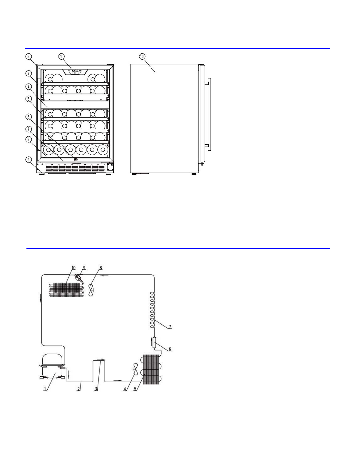
NAME OF PARTS…………………………………………………………………………………………………..……..…….………………3
REFRIGERANT CYCLE DIAGRAM…………………………………………………………………………………………...………..…….3
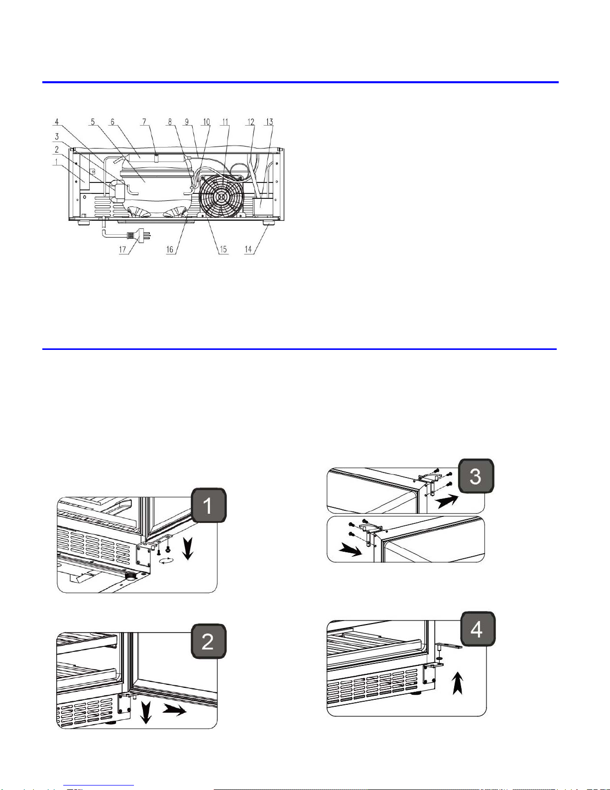
COMPRESSOR ROOM VIEW AND PARTS LIST…………………………………………………..…….……………….………..……....4
HOW TO REVERSE THE DOOR SWING……………………………………………………………………….……………………..…...4-5
HOW TO ATTACHING THE DOOR HANDLE…………………………………………………………….………………………………….5
HOW TO REMOVE THE SHELVES………………….…………………………………………………………..……..……………….…….6
HOW TO REPLACE THE MAIN PARTS………………………………………………………………………………..…………………6-11
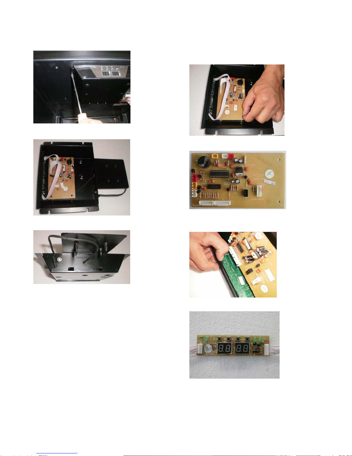
REPLACING THE CONTROL PCB , DISPLAY PCB ,UPPER ZONE SENSER & UPPER ZONE LED ASSEMBLY ….....…….…6-7
REPLACE THE POWER PCB & TRANSFORME…………………..…………………………………….…………...……………..…..…..8
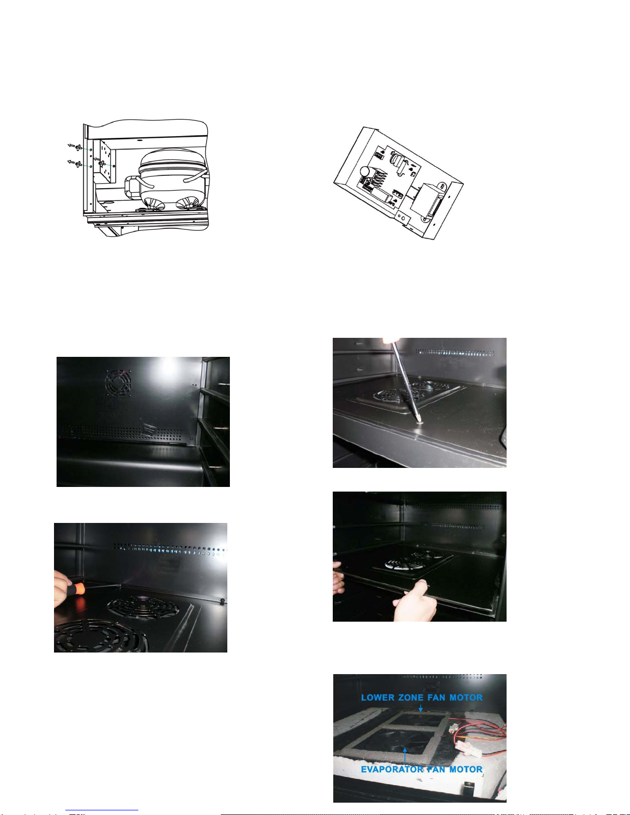
REPLACING THE LOWER ZONE LED LIGHT ASSEMBLY ,EVAPORATOR, PTC HEATER, FAN MOTORS & SENSORS….8-10
REPLACE THE CONDENSER FAN MOTOR ,COMPRESSOR STARTER & PROTECTOR………..………………………...…….. 11
ADJUSTMENT………………………………………………………………………………………………….…………..….………...….12-14
COOLING SYSTEM FAULTS……………..………...…………………………………………………………………….….…..…….……..12
PTC HEATER FAULTS……………..………...……………………………………………………………………..….……………….…12-13
NOISE OF WINE COOLLER……………..………...……………………………………………………………………………...………….13
EVAPORATOR FREEZING……...………………………………………………………………………………………..………………13-14
DESCRIPTION OF CONTROL PCB & POWER PCB………………………………………………………………………….….……….14
TROUBLESHOOTING…………………………………………………………………………………………………..……………………..15
TROUBLES SHOOTING GUIDE……………………………………………………………………………………..…..…………….….….15
SAFETY PRECAUTIONS
Please read the followingsbefore servicing your wine storage
1. Check if an electric leakage occurs in the set.
2. To prevent electric shock, unplug prior to servicing.
3. In case of testing with power on, wear rubber
gloves to prevent electric shock.
4. If you use any appliances, check regular current,
voltage and capacity.
5. Don't touch metal products in cold freezer with wet
hand. It may cause frostbite.
6. Prevent water flowing to electric elements in
mechanical parts.
7. When servicing evaporator part, wear cotton
gloves without fail. It is to prevent wound by
sharp fin of evaporator.
8. Leave a breakage of refrigerating cycle to a
heavy service center. The gas in cycle inside
may soil ambient air.
9. Never clean appliance parts with flammable fluids.
The fumes can create a fire hazard or explosion.

3
1. NAME OF PARTS
1. DIGITAL CONTROL PANEL
2. GLASS DOOR
3. STAINLESS STEEL HANDLE
4. MIDDLE PARTITION
5. LARGE SHELVES
6. SECURITY LOCK
7. BOTTOM SHELF
8. BOTTOM GRILLE
9. LEVELING LEGS
10. CABINET
2. REFRIGERANT CYCLE DIAGRAM
1. Compressor
2. Hot Pipe
3. Condenser (Internal)
4. Condenser Fan
5. Condenser (External)
6. Dry Filter
7. Capillary
8. Evaporator Fan
9. Accumulator
10. Evaporator

4
3. COMPRESSOR ROOM VIEW AND PARTS LIST
1. Junction Box
2. Electrical Box of Compressor
3. Process Pipe
4. Outlet Pipe of Condenser
5. Compressor
6. Dry Filter
7. Dry Filter Clamp
8. Suction Pipe
9. Capillary
10. Discharge Pipe
11. Condenser Fan Motor
12. Drain Pipe
13. Water Drip Tray
14. Rear Leveling Leg
15. Compressor Base
16. Compressor Leg
17. Power Supply Cord with Plug
4. HOW TO REVERSE THE DOOR SWING
This appliance has the capability of the door opening from either the left or right side. The unit is delivered
to you with the door opening from the left side. Should you desire to reverse the opening direction, please
follow these instructions.
Note: All parts removed must be saved to do the reinstatement of door.
1. Open the glass door and remove the two screws
under the right bottom corner of the glass door that
are used to hold the lower hinge to the glass door.
Be careful to hold the glass door with hands from
dropping after removing the screws.
2. Pull down to remove the glass door and place it on a
padded surface to prevent scratching it.
3. Remove the right upper hinge . Install the left upper
hinge from the plastic bag that includes the
instruction manual.
4. Remove the two decoration screws underneath the lower
left corner of glass door.Then install and tighten them at
the opposite designated holes..Remove the lower
door hinge supporter and bush.

5
5. Remove the lower door hinge from the right side.
Remove the three screws that are used to fix the
bottom grille with cabinet then install the three
screws at the designated position at the right side.
6. Install the lower door hinge to the designated
position at the left side.
7. Install the lower hinge supporter together with the
bush to the designated position.
8. Locate and press the glass door up into the upper
hinge pivot and install the two lock screws to connect
the lower hinge with the glass door and tighten them
before the door is leveled.Then remove the handle
from the left side and install it on the right side of the
door.
5. HOW TO ATTACHING THE DOOR HANDLE
1. Pull away the door gasket○
a around the area where the handle is to be installed.(AS INDICATED IN
ILLUSTRATION 1)
NOTE: The gasket is easily displaced by hand ,no tools are necessary.
2. Using a “一” type head screwdriver remove the two pre-installed decorative plugs○
b from the back of door.
Some wine cellar items have no decorative plugs. (AS INDICATED IN ILLUSTRATION 1)
NOTE: Save the decorative plugs for future use .
3. Insert the two “+” type head screws○
c with the lock washers○
d and flat washers○
e through the gasket side
of the door frame until the screws pass right through the door. (AS INDICATED IN ILLUSTRATION 2)
4. Align the handle○
f with the screws and tighten using a “+” type head screwdriver until the handle sets flush
against the door frame. (AS INDICATED IN ILLUSTRATION 2)
NOTE: Do not overtighten as this will cause damage to the handle assembly.
5. Replace the door gasket to its original position.

6
6. HOW TO REMOVE THE SHELVES
To prevent damaging the door gasket, make sure to have the door all the way opened when pulling the bottom
shelf out of the rail compartment.
For easy access to the storage content, you must pull the shelf approximately 1/2 out of the rail compartment,
however this unit was designed with a plastic post on each sides of the shelf track to prevent bottles from
falling.
When removing the shelf out of the inner rail, make sure to remove all items first. Then move the shelf to the
position where the notch of shelf is exactly under the plastic post and lift the shelf. In order to replace the shelf,
repeat steps described above in reverse.
7. HOW TO REPLACE THE MAIN PARTS
7.1 REPLACING THE CONTROL PCB, DISPLAY PCB, UPPER ZONE SENSER & UPPER ZONE LED
ASSEMBLY
1. Remove all the shelves”.
2. Remove one screw that are used to fix the lamp
cover with the cabinet.
3. Take away the lamp cover.
4. Disconnect the wire of LED assembly.
5. Press the plastic nail supporting the LED assembly
with forefinger and thumb,pull the LED assembly
upward,take away it ,then you can replace the new
LED assembly.

7
6. Remove four screws that are used to fix control
PCB box with the cabinet.
7. Disconnect all the wires and pull out the control
PCB box.
8. The upper zone senser is located in the following
position.
9. Press the plastic nail supporting the control PCB
with forefinger and thumb, pull the control PCB
upward,take away it ,then you can replace the
new control PCB.
10. The control PCB is such following figure.
11. Disjoin the claws of the display PCB fixing and take
out the display PCB.
12. The display PCB is such following figure.

8
7.2 REPLACING THE POWER PCB AND TRANSFORMER
1. Remove the three screws that are used to fix the
junction box with the cabinet in the compressor room.
2. Disconnect all connectors on the Power PCB in the
junction box then you can replace the Power PCB
and Transformer.
7.3 REPLACING THELOWERZONELEDLIGHTASSEMBLY,EVAPORATOR, PTC HEATER, FAN MOTORS &
SENSORS
1. Remove all the shelves according to “How to
remove the shelves”.
2. The lower zone sensor and PTC heater fan motor
are located in the following position.
3. Remove the two screws that are used to connect the
top plate of middle partition with the rear air duct
cover.
4. Remove the two screws that are used to connect the
top plate of middle partition with the bottom plate of
middle partition.
5. Pull out the top plate of middle partition.
6. The lower zone fan motor & evaporator fan motor
are located in the following position.(The evaporator
fan motor connect to red wire and the lower zone fan
motor connect to yellow wire.)

9
7. Disconnect the wires then you can replace the
evaporator fan motor and lower zone fan motor.
8. Remove two screws that are used to fix the bottom
plate of middle partition with the cabinet.
9. Remove two screws that are used to fix the bottom
plate of middle partition with the rear air duct cover.
10. Remove one screw that are used to fix the light
cover with the bottom plate of middle partition.
11. Disconnect the housing from the LED light
assembly.In this step, If it’s necessary, you can
replace the LED light assembly.
12.Remove the the bottom plate of middle partition.
13.remove the screws that are used to fix the rear air
duct cover with the cabinet.
14.The evaporator is located in the following position.

10
15.The defrost senser is located in the following position.
16.The PTC heater is located in the following position.
17.Remove the fixing screws then you can replace the
PTC heater.
18.For details of how to replace the upper zone sensor
& lower zone sensor,please follow these instructions.
A. Disconnect all the wires the pull out the rear air duct
cover. Press the nails fixing the senser cover use
screwdriver at the back of the rear air duct cover.
B. Take away the sensor cover from the rear air duct
cover.
C. Take away the sensor from sensor cover.
D. Remove the nails from sensor cover & replace the
new sensor.
E. Press the nails at the ends of the sensor cover use
screwdriver.

11
7.4 REPLACING THE CONDENSER FAN MOTOR ,COMPRESSOR PTC STARTER AND OVERLOAD
PROTECTOR
1. Remove the two screws that are used to fix the
condenser fan motor with the compressor base.
2. Remove the three screws that are used to fix the
junction box with the cabinet.
3. Disconnect the condenser fan motor cables on the
power PCB then you can replace the condenser fan
motor.
4. Remove the clamp that is used to fix the junction
box of compressor .
5. Remove the junction box cover.
6. Disconnect the compressor PTC starter and overload
protector cable with compressor. Now you can
replace the compressor PTC starter and overload
protector.

12
8. ADJUSTMENT
8.1 COOLING SYSTEM FAULTS
HOW TO DIAGNOSE FAULTS
It should take approximately 3 hours to reach the lowest setting temperature of 5℃for an empty unit (assuming
ambient temp of 32 degrees centigrade and continuous operation). If not, check the compressor, cooling fans,
controller, and sensors. If all these are working normally, there is probably a cooling system’s fault.
HOW TO REPAIR THE DEFAULT
1. Check the compressor
Turn on the unit and check there is electricity current flowing to the compressor using a caliper type Amp
meter, the current should be within 0.8 to 2 Amps. If the readings are not in this range, turn off and cut off the
discharge pipe and suction pipe (See COMPRESSOR ROOM VIEW AND PARTS LIST) from the compressor,
then turn the unit on again (in this case only run the compressor for a few minuets, so as to avoid the
compressor absorb moist air) and recheck the current and if there is pressure at the outlet pipe. If the current
reading is still out of range specified above and no pressure from the compressor outlet, replace the whole
compressor.
2. Check the cooling system pipe work
Carefully check the cooling system after verifying the compressor is working normally. Then follow the procedure
below.
1>. Then cut off process pipe and check the refrigerant. If there is not enough refrigerant, the fault of the refrigerant
system should be caused by the leaking. If the refrigerant is sufficient., it is probably jamed in the capillary.
2>.If the fault is on the cooling system,.
A. Infuse 0.8-1.5MP nitrogen by process pipe. test the leakage if the cooling system of the soldering point with the
soap water. Check from the the soldering point arround the compressor, and if everything is ok, remove the air-
duct board and check the soldering point around evaporator. please see the remove method and the procedure
as “6.3 REPLACING THE EVAPORATOR, PTC HEATER, CONTROL PCB,FAN MOTORS & SENSORS”.
B. Make sure the cooling system of the soldering point is normally, Then cut off the capilary around the dry filter,and
infuse 0.8-1MP nitrogen by process pipe, and please put the hand close to the cut kerf of the capilary. If there is a
little gas leak form the terminal, it means normal, or it is jamed.
C. If all the soldering point is not leaking and the capillary isn’t jamed, there are two possibility, one is leakage in the
inner condenser, another is the damage on the parts(such as evaporator,condenser and so on)in the cooling
system. If it is the inner damage, it can not be repaired, and if the damage on the parts, replace them.
3>. Make sure that there is not leakage in the cooling system, refill the refrigerant.
3. Refill the refrigerant:
1>. Using the vacuum pump form a vacuum in the system, via the joint of the low-pressure process pipe on the
compressor , the high-pressure pipeline is on the process pipe of the filter. Apply the vacuum pump for
approximately 20 minutes. Until the vacuum is lower than 100Pa. Then solder the compressor process pipe of
the filter. Keep the vacuum running while soldering this joint
2>.Fill Cooling system with refrigerant via the process pipe. (The refrigerant is R134a. Regarding refrigerant quantity
Please refer to the instruction at back label of wine cellar). Then solder the compressor process pipe after the
system is charged with refrigerant.
8.2 PTC HEATER FAULTS
HOW TO DIAGNOSE FAULTS
If the temperature of refrigeration compartment is 2℃lower than setting temperature for an empty unit (assuming
ambient temp of over 0 degrees centigrade and continuous operation and normal temperature of the freezing
compartment), the heater fan and PTC should run normally,otherwise check the heater fan and PTC heater. If both
are working normally, there is probably a heating system fault.
HOW TO REPAIR THE DEFAULT
1. How to check the heater fan.
If the temperature of refrigeration compartment is lower than set temperature but heater fan does not function, after

13
verifying no bad connections replace the fan unit .
2. How to check the PTC heater
Check the resistance of PTC heater using a Multimeter; the reading should be approx 1.5 KΩ(assuming normal
temperature), if open circuits Replace the PTC heater having once verified the connections to the PTC
heater.Replace new one.
3. If no fault in the fan or PTC heater, replace the main PCB,
8.3 NOISE OF WINE COOLER
COMPRESSOR NOISE
1. The working of motor and piston motion will cause noise when compressor working. So if noise is steady and not
exceeds 42 dB, it’s normal. If noise is not steady or very high, it’s compressor fault and it should be repaired or
replaced.
2. If compressor’s shock absorption rubber is hardening or damaged, or fixing screw of compressor is too tight or
loose, it will cause noise. The settlement is to change new shock absorption rubber or adjust fixing screws.
FAN NOISE
1. When the fans are running , the vanes are circumrotating rapidly and the air flows, which will cause steady and
standard noise. The noise should not exceed 32dB and it is normal.
2. If the noise is extremely high and abnormal, the cause maybe as below
a. The axis of the fan is broken
b. The fan is broken and lost balance
REFRIGERANT JET NOISE
COMPLAINT: If here is intermittent noise like a water spray from the capillary.
CAUSE: The end of the capillary in the evaporator is in the wrong position, or there are rough edges on the end of
the capillary
REMEDY:
1>. Heat the soldered joint of the capillary (“A” of Fig.8), then remove the capillary from the evaporator and smooth
the end with an eraser. (Caution: do not allow any particles into capillary unit)
2>. Replace the capillary into the evaporator, then solder it back into the correct position (not exceeding 15mm in
the evaporator) and pack the joint with anti vibration compound
3>. Recharge with refrigerant.
CAPILLARY VIBRATION NOISE
COMPLAINT: high frequency impact noise in capillary Zone.
CAUSE:
1>. The capillary being insert too deep into the evaporator, so when the refrigerant is Jetting, the end of vibrating
capillary will hit the inside of the evaporator.
2>. Vibration from the capillary touching the inside of the cabinet or air duct board, then when refrigerant is jetting.
REMEDY:
1>. If the capillary is inserted too deep, heat it with the solder, solder it again(Please noted, the deep inserted is
not bigger than 15mm), and vacuumize it and add the refrigerant.
2>. If the capillary touch the inner cabinet and the air duct panel, adjust the position of the capillary and add the
incabloc plastic.
OIL JAMMED NOISE
COMPLAINT: intermittent and deep jet noise coming from inside of the capillary.
CAUSE: Compressor oil flowing into the cooling system pipe work because of wine cooler lean during
transportation, and the jetting oil in the capillary cause noise.
REMEDY:Clean the cooling system pipe, and recharge with refrigerant
8.4 EVAPORATOR FREEZING
CAUSE:The gasket is not air-proof, or the door is not closed well, cause much water fill in the the cabinet, and the
water got frozen when it encounter the cold air, sometimes the ice is too thick, and it will block the fan or
broken the fan.

14
REMEDY:
1>. Replace the door gasket or close the door well. If the door gasket is slightly not air-proof, it can be repaired
by the heat dryer.Aiming at the distortion of the gasket with the heat dryer, and move up and down until it
expand to the normal state. When it is cool, check it with the door closed, if there is any distortion, dry it
again until it fix for the door.
2 >.If the fan is Jamed seriously or breacken, replace it with the new fan.
9. DESCRIPTION OF CONTROL PCB & POWER PCB
CONTROL PCB
1.To Evaporator Fan Motor(Red)
2.To Lower Zone Fan Motor(Yellow)
3.To PTC Heater Fan Motor(White)
4.To Upper Zone Sensor(Yellow)
5.To Lower Zone Sensor(White)
6.To Defrost Sensor(Red)
7.To LED Light Assembly
8.To Power PCB
9.To Display PCB
POWER PCB
1. To Trasformer Input L,N
2. To Power L,N
3. To Trasformer Output
4. To Condenser Fan Motor
5. To PTC Heater
6. To Compressor
7. To Control PCB

15
10. TROUBLESHOOTING
10.1 Troubleshooting Guide
P
R
OBLEM
POSSIBLE CAUSE
Wine Chiller does not operate. Not plugged in.
The appliance is turned off.
The circuit breaker tripped or a blown fuse.
Wine Chiller is not cold enough.
Check the temperature control setting.
External environment may require a higher
setting.
The door is opened too often.
The door is not closed completely.
The door gasket does not seal properly.
Turns on and off frequently.
The room temperature is hotter than normal.
A large amount of contents has been added to the
wine chiller.
The door is opened too often.
The door is not closed completely.
The temperature control is not set correctly.
The door gasket does not seal properly.
The light does not work. Not plugged in.
The circuit breaker tripped or a blown fuse.
The bulb has burned out.
The light button is “OFF”.
Vibrations. Check to assure that the Wine Chiller is level.
The Wine Chiller seems to make too much noise.
The rattling noise may come from the flow of the
refrigerant, which is normal.
As each cycle ends, you may hear gurgling
sounds caused by the flow of refrigerant in your
Wine Chiller.
Contraction and expansion of the inside walls
may cause popping and crackling noises.
The Wine Chiller is not level.
The door will not close properly.
The Wine Chiller is not level.
The door was reversed and not properly installed.
The gasket is dirty.
The shelves are out of position.
Display error code “E3” or “E4”.
The defrost sensor is failed.This sensor is
connected to the main control PCB in red color
wires.
Display error code “E7” or “E8”. The Lower Zone Sensor is failed. This sensor is
connected to the main control PCB in white color
wires
Display error code “E1” or “E2”. The Upper Zone Sensor is failed. This sensor is
connected to the main control PCB in yellow color
wires
Other manuals for CWR460DZ
1
Table of contents
Other EdgeStar Wine Cooler manuals

EdgeStar
EdgeStar AVALLON User manual

EdgeStar
EdgeStar TWR325ESS User manual

EdgeStar
EdgeStar CWF440SZ User manual

EdgeStar
EdgeStar TWR182ESS User manual

EdgeStar
EdgeStar CWB2886FD User manual

EdgeStar
EdgeStar CWR260DZ User manual

EdgeStar
EdgeStar CWB2150FD User manual

EdgeStar
EdgeStar CWR450DZ User manual

EdgeStar
EdgeStar CWR265SZ User manual
Popular Wine Cooler manuals by other brands

Danby
Danby DWC018A1BDB Owner's use and care guide

Eurocave
Eurocave INOA 25 instruction manual

Avanti
Avanti WCR5450DZ instruction manual

Vinotemp
Vinotemp VT24 instruction manual

Gastrodomus
Gastrodomus CW 500 instruction manual

GE
GE PWR04FANBS - Profile - 20in Wine Center Dimensions and installation information