EDWANZ group DEUTRONIC D-IBM2900 User manual

Deutronic Elektronik GmbH
Deutronicstr. 5, D - 84166 Adlkofen
Tel.: +49 8707 920-0
Fax: +49 8707 1004
http://www.deutronic.com
D-IBM2900 Stand: 08.03.2022 Seite 1 von 25
Operation Manual
D-IBM2900

Deutronic Elektronik GmbH
Deutronicstr. 5, D - 84166 Adlkofen
Tel.: +49 8707 920-0
Fax: +49 8707 1004
http://www.deutronic.com
D-IBM2900 Stand: 08.03.2022 Seite 2 von 25
Table of Content
Operation Manual ................................................................................................................. 1
D-IBM2900 ............................................................................................................................ 1
Warnings and Categories ...................................................................................................... 4
Intended se .................................................................................................................... 5
Mounting and Installation ................................................................................................. 5
Service, Maintenance and Support ................................................................................... 6
Accessory and Spare Parts ................................................................................................ 6
Environment Protection .................................................................................................... 6
Product Description ............................................................................................................... 7
LED-Display: ..................................................................................................................... 8
Components/Connections to the device: ......................................................................... 9
Technical Data .................................................................................................................12
Installation and Commissioning ............................................................................................13
Check before the initial Commissioning ..........................................................................13
Connecting the battery and Commissioning ....................................................................13
Transport and Storage..........................................................................................................16
Discharging Time .............................................................................................................17
Storage over two Weeks ..................................................................................................17
Exchange Battery Modules ..............................................................................................19
Error Detection .....................................................................................................................20
Total device: ....................................................................................................................20
Check of the Functionality of the Battery Modules: .........................................................20
Overview..........................................................................................................................21
Packaging and Dispatch .......................................................................................................22
Disposal ...............................................................................................................................25

Deutronic Elektronik GmbH
Deutronicstr. 5, D - 84166 Adlkofen
Tel.: +49 8707 920-0
Fax: +49 8707 1004
http://www.deutronic.com
D-IBM2900 Stand: 08.03.2022 Seite 3 von 25
The following installation and safety notes must be followed before commissioning the D-
IBM2900-3AC or D-IBM2900-1AC (hereinafter referred to as device).
To recognize existing danger potentials and minimize the risk of personal injury and
property damage, important information is provided to the user (also referred to as system
integrator).
This document does not raise any claim to completeness and considers the dangers known
to the manufacturer.
The device may only be operated by qualified and trained personnel.
The device must be considered as a system component. The system integrator is
responsible for the applicability of the device in the application, including risk analysis. The
model-specific data sheets must always be considered.
Keep this instruction easily accessible at all times.
The content is valid for the following products:
•D-IBM2900-3AC
•D-IBM2900-1AC

Deutronic Elektronik GmbH
Deutronicstr. 5, D - 84166 Adlkofen
Tel.: +49 8707 920-0
Fax: +49 8707 1004
http://www.deutronic.com
D-IBM2900 Stand: 08.03.2022 Seite 4 von 25
Warnings and Categories
Warnings must always be observed and are therefore marked specially. They include
information on personal injuries and property damage so that accidents and damages can
be avoided.
Device Labelling
Device and Documentation Labelling
Read th
e operation manual
Information
Warning of electrical voltage
Note
General warning sign, describes the imminent
danger that can lead to grievous bodily harm or
to death.
-
Additional warnings and notes on the device

Deutronic Elektronik GmbH
Deutronicstr. 5, D - 84166 Adlkofen
Tel.: +49 8707 920-0
Fax: +49 8707 1004
http://www.deutronic.com
D-IBM2900 Stand: 08.03.2022 Seite 5 von 25
General applicable safety notes
se eye protection
Observe handling
instructions
se hand protection
Intended Use
This product is exclusively intended for the product description in this chapter. Each further
use is not intended and Deutronic does not assume liability for the damages incurred by
this. The risk is borne solely by the user/operator.
Mounting and Installation
- Wear your personal protection equipment
- Mounting and installation of the product only by qualified personnel.
- Mains/DC cables may only be used completely unrolled to guarantee a sufficient
cooling!
- Ensure a safe locking of the plug connectors to guarantee operational safety and
avoid damages. In case of wear, the cable must be replaced immediately!
- Disconnecting the plug connection during use is prohibited.
- The devices may only installed in locations that meet the climatic and technical
conditions specified by Deutronic (see technical data). D
- Deutronic is not liable for damage caused by improper handling or incorrect
installation.
- Only carry out works on parts of the device when it is switched off.
- Protect from direct sunlight.
- Protect from heat sources.
- The device must be protected from water and humidity. Water penetration damages
the battery.
- The device must be mounted in such a way that an operation is possible and the
device status can be read by the user.
- If the operating position is wrong, there is risk of injury from tipping.
- It is forbidden to change the device mechanically such as drilling holes to attach
additional mounting points.
- Any modification to the device can lead to life-threatening operating conditions or
fire.

Deutronic Elektronik GmbH
Deutronicstr. 5, D - 84166 Adlkofen
Tel.: +49 8707 920-0
Fax: +49 8707 1004
http://www.deutronic.com
D-IBM2900 Stand: 08.03.2022 Seite 6 von 25
Service, Maintenance and Support
Service, maintenance and support are carried out by Deutronic or partners of Deutronic.
Accessor and Spare Parts
Accessories and spare parts are obtained from:
Deutronic Elektronik GmbH
Deutronicstraße 5
D-84166 Adlkofen
Tel: +49 8707 920-0
sales(at)deutronic.com
Environmental Protection
The products by Deutronic are designed with eco-design in mind to minimize their impact
on the environment. The following characteristics are considered as standard by Deutronic
during the design of our products:
•The products by Deutronic are made out of high-quality materials to maximize their
lifespan.
•The product design allows the separation of different materials for reprocessing and
efficient recycling.
•Deutronic is always working to further develop its products and to continuously
reduce the environmental impact of them.
Deutronic’s products serve to use energy more efficiently and thereby reduce the everyday
environmental impact. Deutronic tries to mitigate the impact on people and the
environment during the entire product cycle and to return as much as possible to the
material cycle. It is important that the user handles all products with care and uses them
efficiently.
For information on the return and disposal of the products, see chapter Disposal.

Deutronic Elektronik GmbH
Deutronicstr. 5, D - 84166 Adlkofen
Tel.: +49 8707 920-0
Fax: +49 8707 1004
http://www.deutronic.com
D-IBM2900 Stand: 08.03.2022 Seite 7 von 25
Product Description
The device serves as a device that’s pre-switched to the Deutronic battery charger to ensure
uninterruptible voltage supply in production areas where no conveyor supply is possible. A
unit consists of 8 battery modules with 16S1P Samsung INR18650-29E, fused by a 15A BMS.
The charging technology for the battery modules is integrated.
Deutronic Elektronik GmbH
Deutronicstr. 5, D - 84166 Adlkofen
Tel.: +49 8707 920-0
Fax: +49 8707 1004
http://www.deutronic.com
D-IBM2900 Stand: 08.03.2022 Seite 8 von 25
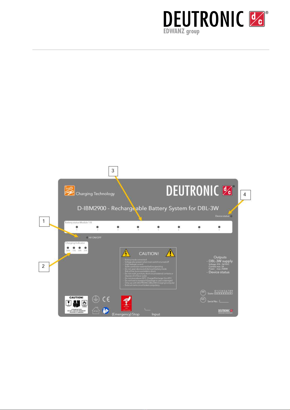
LED-Displa :
1.
HV ON/OFF (Battery)
2.
Charging condition 25%, 50%, 75%, 100%
3.
Battery module state (from Gen3)
4.
Device error (from Gen3)

Deutronic Elektronik GmbH
Deutronicstr. 5, D - 84166 Adlkofen
Tel.: +49 8707 920-0
Fax: +49 8707 1004
http://www.deutronic.com
D-IBM2900 Stand: 08.03.2022 Seite 9 von 25
Components/Connections to the device:
1.
(Emergency)Off switch draw release, protection class: IP66/IP69k
2.
Fan
3.
Input plug connector Harting HAN 6E/B, 6-pole, male
(1AC with HAN 4-pole)
PIN ”1”: L1
PIN ”2”: L2
PIN ”3”: N (assignment not required)
PIN ”4”: L3
PIN ”5”: Interlock safety circuit
PIN ”6”: Interlock safety circuit
GND: PE (contacts external)
Assignment of the connection of the center conductor N is not necessary!
Jumper Pin 5 and 6 (safety circuit): A jumper in the supply line between Pin5 and Pin6
ensures that the device cannot be activated if the plug is not properly attached to the device.
The jumper must be provided in the supply line.
4.
Device output Cable connection with connection socket
Harting HAN 6E/B, 6-pole, female
PIN ”1”: + VDC
PIN ”2”: - VDC
PIN ”3”: not assigned
PIN ”4”: not assigned
PIN ”5”: not assigned
PIN ”6”: not assigned
GND: PE (contacts external)
Deutronic Elektronik GmbH
Deutronicstr. 5, D - 84166 Adlkofen
Tel.: +49 8707 920-0
Fax: +49 8707 1004
http://www.deutronic.com
D-IBM2900 Stand: 08.03.2022 Seite 10 von 25
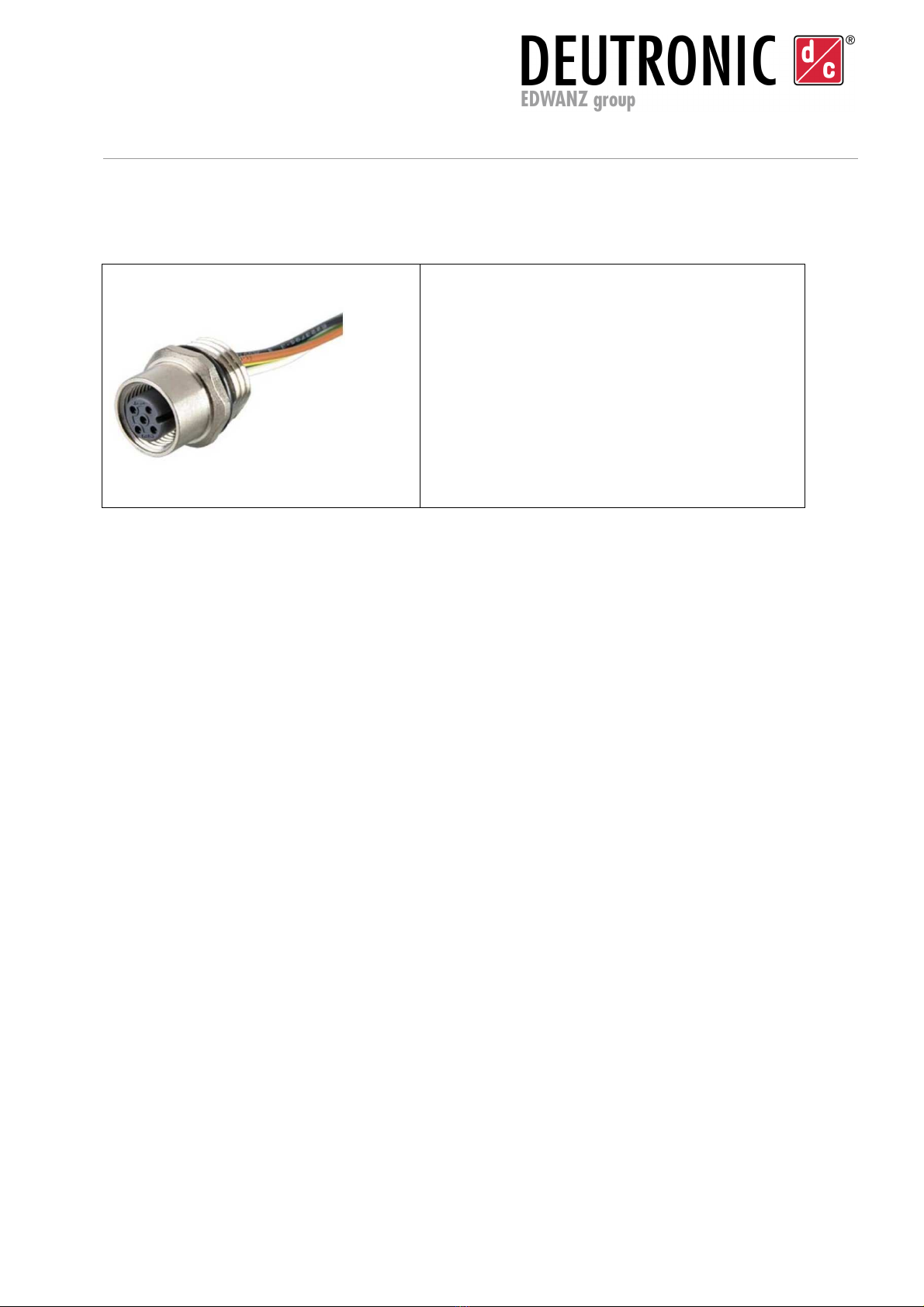
5.
Output device error (only 3AC) CONEC plug 43-01001
An error evaluation of an external system can
only be carried out via a NO/NC relay contact
via a NO/NC relay contact
PIN ”1”: brown, center contact/ switching contact
PIN ”2”: white, normally open
PIN ”3”: blue, normally closed
PIN ”4”: black, not assigned
PIN ”5”: green/yellow, not assigned
Functionality Device Error:
From D-IBM2900 Gen3 on, the device are equipped with an error output in form of a
potential-free contact (NO/NC relays contact in the device). This can be used to implement
an error evaluation via an external system (e.g. PLC).
When all accumulators have reached the minimum voltage of approx. 58V, the NO contact
is closed. The relay is always supplied with voltage as soon as all accumulator modules are
in a functional state and charged. It will not open again until one of the battery voltages
drops below 51V, the battery is defective, or the cell temperature has risen above 70°C.
The fault activation occurs immediately (without any time delay) and is independent of the
supply situation of the device. Thus, even before the power supply to the DBL is
interrupted, the fault is detected and can be rectified.
The intelligent charging technology attempts to charge a defective battery, which no longer
has any internal voltage, up to 12 times with interruptions for approx. 10 sec. After that, no
further charging attempt is made. This causes the error signal to be interrupted up to 12
times during this time, but then to be evaluated continuously. After an overtemperature
error, which does not occur during normal operation, the D-IBM must therefore be
disconnected from the mains for 30 sec. Disconnected from the mains. After that it goes
back to normal operation. A device with a defective battery module shows the behavior
after the mains connection that it clears the error 12 times for approx. 10 seconds, but then
remains continuously on fault.

Deutronic Elektronik GmbH
Deutronicstr. 5, D - 84166 Adlkofen
Tel.: +49 8707 920-0
Fax: +49 8707 1004
http://www.deutronic.com
D-IBM2900 Stand: 08.03.2022 Seite 11 von 25

Deutronic Elektronik GmbH
Deutronicstr. 5, D - 84166 Adlkofen
Tel.: +49 8707 920-0
Fax: +49 8707 1004
http://www.deutronic.com
D-IBM2900 Stand: 08.03.2022 Seite 12 von 25
Technical Data
D-IBM2900-3AC
Input
Input voltage range 320 – 550VAC
Protection class I
Inrush current:: Inrush current impulse, actively controlled <= 70A +/- 10%
Power consumption during
full load
<10A (internal device fuse)
Transient overvoltage
protection
EN60335
Input fuse External 3 pole LS switch 16A, preconnect characteristic B
Idle power (Stand-by): <60 Watt
The AC/DC converters feature Power Factor Correction current
limiting
Output
Output voltage: Battery operation: 410 - 550VDC
Mains operation: 430 - 740VDC (rectifier voltage from bypass)
Nominal voltage: 460VDC
Length of the output line: 2 m
Output safety circuit fuse 1000VDC 6A IEC60269-4
Overall efficiency >77%
Operating Conditions Industrial environment
Mechanical Data/ Environmental Influences
Protection class: IP20
Operation temperatures: 0 to +45°C
Environment temperature: 0 to +45°C
Storage temperature: -10 to + 45°C
Cooling: Active, with fan
Rel. humidity 5 to 95% humidity, non-condensing
Isolation voltage: 1000 VDC of all inputs and outputs against PE
Housing: Plastic and aluminum
Dimensions: Ca. 450x550x170 mm
Deutronic Elektronik GmbH
Deutronicstr. 5, D - 84166 Adlkofen
Tel.: +49 8707 920-0
Fax: +49 8707 1004
http://www.deutronic.com
D-IBM2900 Stand: 08.03.2022 Seite 13 von 25
Installation and Commissioning
Check before the initial Commissioning
•Check the delivery immediately after receipt for completeness and any transport
damage, e.g. mechanical damage to the device housing, as well as to cables or
accessories.
•If there is any damage, the transport company must be notified immediately.
•If damage to the device, cables or accessories is detected or suspected, the
installation and commissioning must not be continued under any circumstances.
•In this case, the device must be marked as defective.
•Do not continue to use the device after a hard impact or damage caused by a fall.
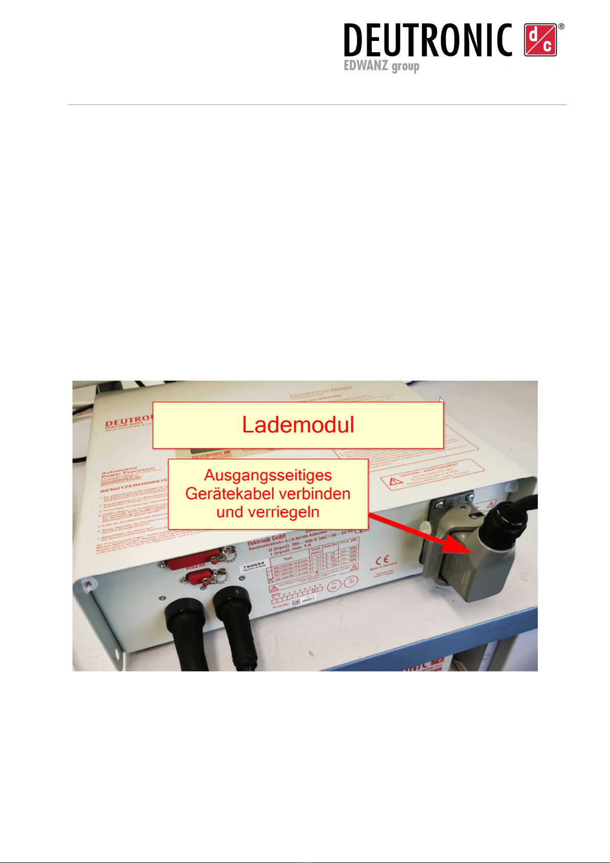
Connecting the batter and Commissioning
1. Connect and lock the output side (fixed) cable from the device to the charging
module.

Deutronic Elektronik GmbH
Deutronicstr. 5, D - 84166 Adlkofen
Tel.: +49 8707 920-0
Fax: +49 8707 1004
http://www.deutronic.com
D-IBM2900 Stand: 08.03.2022 Seite 14 von 25
2. Connect the power cable to the supply mains and lock it.
3. Release the emergency off and check the charging indicator. Charging indicator
lights up.

Deutronic Elektronik GmbH
Deutronicstr. 5, D - 84166 Adlkofen
Tel.: +49 8707 920-0
Fax: +49 8707 1004
http://www.deutronic.com
D-IBM2900 Stand: 08.03.2022 Seite 15 von 25
Charging indicator:
1x Green = 50%
2x Green = 75%
3x Green = 100%
All LEDs off means that the device is discharged, no sufficient capacity available which is
done automatically.

Deutronic Elektronik GmbH
Deutronicstr. 5, D - 84166 Adlkofen
Tel.: +49 8707 920-0
Fax: +49 8707 1004
http://www.deutronic.com
D-IBM2900 Stand: 08.03.2022 Seite 16 von 25
Transport and Storage
Possible damages to the internal battery technology due to defects of the
housing (visual inspection).
Check the device for damages
Do not commission defective batteries!
- The storage of batteries below -10°C and above 45°C can lead to
damages.
-
Humidity during storage must be within 5
-
95%. Non
-
condensing.
- If the storage takes longer than 2 weeks, it is recommended to disconnect
the battery packs from the whole system.

Deutronic Elektronik GmbH
Deutronicstr. 5, D - 84166 Adlkofen
Tel.: +49 8707 920-0
Fax: +49 8707 1004
http://www.deutronic.com
D-IBM2900 Stand: 08.03.2022 Seite 17 von 25
Discharging Time
The following are empirical values for the discharge duration of the D-IBM2900-3AC at the
following ambient conditions:
- Ambient temperature 20°C
- Start SOC: 100%
- Start SOH: 100% (as new battery modules)
The Gen2/3 devices are shipped with a SOC of approx. 20% and in "transport mode"
(unplugged battery modules) and are discharged in this state after approx. 6 weeks.
Passive D-IBM2900, Safety Circuit open:
As soon as the D-IBM2900 has been commissioned (battery modules plugged in), the
master board with the higher-level BMS is active and constantly monitors the overall system.
Therefore, in case of longer standstill times >24 hours and missing voltage supply via the
three-phase connection (400VAC) - i.e. in pure battery operation - the safety circuit (see
chapter 0- 3. Input connector) PIN 5 and 6 should be opened. This can also be done by
actuating the (emergency) off switch (see chapter 0 - 1. (Emergency) off switch). If the safety
circuit is opened at a SOC=100%, the discharge duration is approx. 80 hours.
Storage over two Weeks
If storage is planned for longer than 2 weeks, we recommend deactivating the individual
battery packs within the storage module to prevent deep discharge of the individual
modules. The state of charge should ideally be between 50% and 75% before deactivation.
1. make sure that the emergency stop switch is actuated! LED HV ON and SOC
(100%, 75%, 50% and 25%) are off.
2. To do this, open the maintenance cover on the rear of the device by loosening
the 8 fastening screws.

Deutronic Elektronik GmbH
Deutronicstr. 5, D - 84166 Adlkofen
Tel.: +49 8707 920-0
Fax: +49 8707 1004
http://www.deutronic.com
D-IBM2900 Stand: 08.03.2022 Seite 18 von 25
3. Then disconnect the 8 connection terminals and insert them into the dummy
plug trays provided for this purpose on the left side of the battery connections.

Deutronic Elektronik GmbH
Deutronicstr. 5, D - 84166 Adlkofen
Tel.: +49 8707 920-0
Fax: +49 8707 1004
http://www.deutronic.com
D-IBM2900 Stand: 08.03.2022 Seite 19 von 25
Exchange Batter Modules
1. Open the maintenance flap on the rear of the device to allow access to the battery
modules.
2. nplug all battery modules such as shown in “Fehler! Verweisquelle konnte nicht
gefunden werden.
3. Carefully pull out the battery module to be replaced
4. connect all battery modules
5. Close the maintenance flap

Deutronic Elektronik GmbH
Deutronicstr. 5, D - 84166 Adlkofen
Tel.: +49 8707 920-0
Fax: +49 8707 1004
http://www.deutronic.com
D-IBM2900 Stand: 08.03.2022 Seite 20 von 25
Error Detection
Total device:
As soon as the system is supplied with supply voltage, the charging process starts
automatically.
Missing energy is recharged until reaching 100% of the battery condition.
Charging is automatically finished, when the storage is full. The device is designed for the
permanent connection. The four LED red (25%) and the three LED green (50%, 75% and
100%) shine. Additionally, the correct function can also be recognized by the HV O LED.
A malfunction is given, if, despite correct connection of the device to the power
supply, the HV ON LED does not light up. (The D-IBM 2900 must be replaced)
Consequence: The DBL charging computer is not supplied with voltage and the SOC
display remains permanently off.
Deactivate, by pressing the emergency off button, the D IBM and disconnect the device
connections. Replace the D-IBM and recommission it in reverse order. If the battery charge
is below 25% SOC (all LED off), it can take up to 15 minutes until the HV on LED shines and
the SOC display displays the charging condition. A full charge will then take approximately
2,5h. As soon as the HV On LED lights up, the connected DBL charging computer can be
used to its full extent. The charging activity is not affected by this.
Check of the Functionalit of the Batter Modules:
1. In case of a longer storage time, the device must be supplied with mains voltage
before the check to “wake“ the battery modules from sleep mode. To do this, the
emergency off must be unlocked again. The charging technology supplies the
batteries autonomously, so that the functioning modules are charged to be able to
be measured.
2. The LEDs of the battery modules (1 to 8) light up insofar as the SOC allows this.
3. If the LED of a battery module does not light up, then it is suspected that it is not
functional. In this case the module could be unplugged (see picture below) to check
the module voltage (this should be between 51V and 67.2V).
4. If necessary exchange the battery modules.
Table of contents
Other EDWANZ group Diagnostic Equipment manuals


