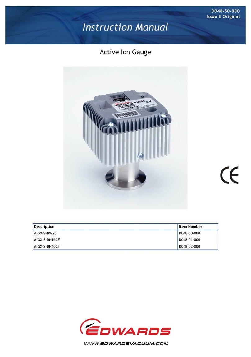
Edwards ASG2-1000-1/8 NPT User manual

D357-35-880
Issue A
Instruction Manual
Active Strain Gauge
Description Item Number
ASG2-1000-1/8 NPT D357-35-000
ASG2-1000-NW16 D357-36-000
ASG2-2000-1/8 NPT D357-37-000
ASG2-2000-NW16 D357-38-000

This product has been manufactured under a quality management system certified to ISO 9001:2008
Declaration of Conformity
We, Edwards Limited,
Crawley Business Quarter,
Manor Royal,
Crawley,
West Sussex, RH10 9LW, UK
declare under our sole responsibility, as manufacturer and person within the EU authorised
to assemble the technical file, that the product(s)
Active Strain Gauge 2
ASG2-1000-1/8 NPT D357-35-000
ASG2-1000-NW16 D357-36-000
ASG2-2000-1/8 NPT D357-37-000
ASG2-2000-NW16 D357-38-000
to which this declaration relates is in conformity with the following standard(s) or other
normative document(s)
EN61326-2-3: 2013 Electrical equipment for measurement, control and laboratory
(Class B Emissions, Use. EMC requirements. Particular requirements. Test
Basic Immunity) configuration, operational conditions and performance criteria
for transducers with integrated or remote signal conditioning
EN50581:2012 Technical Documentation for the Assessment of Electrical and
Electronic Products with respect to the Restriction of Hazardous
Substances
and fulfils all the relevant provisions of
2014/30/EU Electromagnetic Compatibility (EMC) Directive
2012/19/EU Waste from Electrical and Electronic Equipment (WEEE) Directive
2011/65/EU Restriction of Certain Hazardous Substances (RoHS) Directive
Note: This declaration covers all product serial numbers from the date this Declaration was
signed onwards.
15.07.2015, Eastbourne
Larry
Marini,
Senior
Technical Manage
r
Date and Place
P200-06-900 Issue C

© Edwards Limited 2012. All rights reserved. Page i
Edwards and the Edwards logo are trademarks of Edwards Limited.
Contents
D357-35-880 Issue A
Contents
Section Page
1 Introduction .......................................................................................1
1.1 Scope of this manual .................................................................................................... 1
1.2 Description ................................................................................................................ 1
1.3 Gas dependency .......................................................................................................... 1
2 Technical data ....................................................................................3
2.1 Mechanical data .......................................................................................................... 3
2.2 Performance, operation and storage conditions .................................................................... 3
2.3 Electrical data ............................................................................................................ 4
2.4 Material exposed to vacuum ........................................................................................... 4
3 Installation .........................................................................................5
3.1 Unpack and inspect ...................................................................................................... 5
3.2 Fit the ASG2 to the vacuum system ................................................................................... 5
3.3 Electrical connections ................................................................................................... 5
3.3.1 Connect to Edwards controller ........................................................................................ 5
3.3.2 Connect to your own supply and control equipment ............................................................... 5
4 Operation ..........................................................................................9
4.1 Pressure measurement .................................................................................................. 9
5 Maintenance ..................................................................................... 11
5.1 Zero adjustment ........................................................................................................11
5.2 Cleaning ..................................................................................................................12
6 Storage and disposal ........................................................................... 13
6.1 Storage ...................................................................................................................13
6.2 Disposal ...................................................................................................................13
7 Spares and accessories ......................................................................... 15
7.1 Introduction .............................................................................................................15
7.2 Accessories ...............................................................................................................15
For return of equipment, complete the HS Forms at the end of this manual.
Illustrations
Figure Page
1 General views of ASG2 .................................................................................................. 2
2 Dimensions of ASG2 ...................................................................................................... 4
3 Pins on the ASG2 (viewed from above) ............................................................................... 6
4 Pins on the ASG2 adapter cable socket .............................................................................. 6
5 Schematic diagram of typical electrical connections using 4 pin DIN connector .............................. 7
6 Schematic diagram of typical electrical connections using the ASG2 adapter cable ......................... 7
7 Zero and span setting detail ..........................................................................................11
gea/0212/07/12

© Edwards Limited 2012. All rights reserved. Page 1
Edwards and the Edwards logo are trademarks of Edwards Limited.
Introduction
D357-35-880 Issue A
1Introduction
1.1 Scope of this manual
This manual provides installation, operation and maintenance instructions for the Edwards ASG2 (Active Strain
Gauge). You must use the ASG2 as specified in this manual.
Read this manual before you install and operate the ASG2. Important safety information is highlighted as WARNING
and CAUTION instructions; you must obey these instructions. The use of WARNINGS and CAUTIONS is defined below.
CAUTION
Cautions are given where failure to observe the instruction could result in damage to the equipment, associated
equipment or process.
The unit used through this manual conforms to the SI international system of units of measurement.
The following symbols appear on the ASG2:
1.2 Description
The ASG2, shown in Figure 1, is a strain gauge. The measurement range of the ASG2-1000 is 1000 to 1 mbar. The
range of the ASG2-2000 is 2000 to 1 mbar.
The ASG2 requires a 12 to 32 V d.c. power supply: it has a 0 to 10 V d.c. linear analogue output which is related to
pressure. The ASG2 is compatible with all of the Edwards TICs (Turbo/Instrument Controllers), with the ADD (Active
Digital Display) and with the enhanced ADC (Active Digital Controller). Alternatively, you can use an independent
power supply for the ASG2 and can read the ASG2 output signal with a voltmeter or an analogue-to-digital converter.
A standard Active gauge cable plus an ASG2 adapter cable are used to connect the Edwards controller. These are
available as accessories (refer to Section 7.2). To connect to an electrical supply and voltmeter, the 4-way connector
on the gauge head can be used.
A gauge identification signalis incorporated in the adapter cable: this is used by Edwards controllers to identify which
type of active gauge is connected.
1.3 Gas dependency
The pressure sensing technique depends on the deflection of a metal diaphragm. The measurement is therefore
completely independent of gas type.
WARNING
Warnings are given where failure to observe the instruction could result in injury or death to
persons.
Warning - refer to accompanying documentation.
Edwards offers European customers a recycling service.

D357-35-880 Issue A
Page 2 © Edwards Limited 2012. All rights reserved.
Edwards and the Edwards logo are trademarks of Edwards Limited.
Introduction
Figure 1 - General views of ASG2

© Edwards Limited 2012. All rights reserved. Page 3
Edwards and the Edwards logo are trademarks of Edwards Limited.
Technical data
D357-35-880 Issue A
2Technicaldata
2.1 Mechanical data
2.2 Performance, operation and storage conditions
Dimensions See Figure 2
Mass 0.15 kg (NW16)
0.13 kg (1/8” NPT)
Volume of gauge tube
NW16 2.78 cm3
1/8 inch NPT 2.74 cm3
Enclosing rating IP65
Ambient temperature
operation -40 to +80 °C
storage -40 to +80 °C
Compensated temperature -10 to +50 °C
Ambient humidity (operating) 10 to 90% (non-condensing)
Pressure containment 200 bar
Maximum over pressure 4 x full scale with negligible calibration change
Pressure range
ASG2-1000 1000 to 1 mbar
ASG2-2000 2000 to 1 mbar
Accuracy ±0.2% full scale
Stability 0.1% full scale per year
Temperature co-efficient 0.03% full scale per °C

D357-35-880 Issue A
Page 4 © Edwards Limited 2012. All rights reserved.
Edwards and the Edwards logo are trademarks of Edwards Limited.
Technical data
2.3 Electrical data
Note: The relationship between the output signal voltage and the pressure is linear with 10 V corresponding to
the full scale of the gauge (e.g. for 1000 mbar full scale gauge 10 V is equivalent to 1000 mbar, 1 V is
equivalent to 100 mbar, 0.1 V is equivalent to 10 mbar etc).
2.4 Material exposed to vacuum
Stainless Steel 316L
Hastelloy C276
Figure 2 - Dimensions of ASG2
Electrical supply
Voltage 12 to 32 V d.c.
Maximum power 0.1 W
Electrical connector DIN 43650 Form A
Pressure output signal
Nominal range 0 ≤output ≤10 V d.c.
Impedance 51 Ω
Min load >10 kΩ

© Edwards Limited 2012. All rights reserved. Page 5
Edwards and the Edwards logo are trademarks of Edwards Limited.
Installation
D357-35-880 Issue A
3 Installation
3.1 Unpack and inspect
Remove all packing material and protective covers and check the ASG2.
If the ASG2 is damaged, notify your supplier and the carrier in writing within three days; state the Item Number of
the ASG2 together with your order number and your supplier’s invoice number. Retain all packing materials for
inspection. Do not use the ASG2 if it is damaged.
If the ASG2 is not to be used immediately, replace the protective covers. Store the ASG2 in suitable conditions as
described in Section 6.
3.2 Fit the ASG2 to the vacuum system
The ASG2 can be mounted in any orientation. To avoid the build-up of debris or condensable material in the body
tube of the ASG2 we recommend that you install the ASG2 vertically as shown in Figure 2.
To connect the ASG2 to your vacuum system:
Use an O-Ring / centring ring or Co-seal and clamp to connect an NW16 flange to a similar flange on the
vacuum system.
Use a stepped O-Ring carrier or Co-seal to connect an ASG2 with a NW16 flange to a NW10 flange.
Use PTFE tape for 1/8 inch NPT connection.
3.3 Electrical connections
3.3.1 Connect to Edwards controller
Connect the ASG2 to the controller using an adapter cable and an active gauge cable (refer to Section 7).
3.3.2 Connect to your own supply and control equipment
Note: Do not connect the electrical supply common to the signal common. If you do, the ASG2 output signal will
be inaccurate.
If connection is to be made using the 4 pin DIN connector, the pin allocations are as shown in Figure 3.
WARNING
Do not use o-ring/centring rings above atmospheric pressure. A coseal should be used instead.
WARNING
If the ASG2 malfunctions, the ASG2 pressure output may be incorrect. If such a failure could cause
injury to persons or damage equipment, you must install a suitable control system to indicate the
failure and, if necessary, to close down your process system.

D357-35-880 Issue A
Page 6 © Edwards Limited 2012. All rights reserved.
Edwards and the Edwards logo are trademarks of Edwards Limited.
Installation
Figure 3 - Pins on the ASG2 (viewed from above)
If connection using an FCC68 connector is preferred, the ASG2 adapter cable may be used and the pin allocations are
as shown in Figure 4.
Figure 4 - Pins on the ASG2 adapter cable socket
Schematic diagrams of the recommended electrical connections to the ASG2 are shown in Figure 5 and 6.
Pin number Use
1 Electrical supply positive voltage
2 Electrical supply common
3 Pressure measurement output signal
4Outputcommon
Pin number Use
1 Electrical supply positive voltage
2 Electrical supply common
3 Pressure measurement output signal
4 Gauge identification signal
5 Signal common
6 No connection
7 No connection
8 No connection

© Edwards Limited 2012. All rights reserved. Page 7
Edwards and the Edwards logo are trademarks of Edwards Limited.
Installation
D357-35-880 Issue A
Figure 5 - Schematic diagram of typical electrical connections using 4 pin DIN connector
Figure 6 - Schematic diagram of typical electrical connections using the ASG2 adapter cable
1. ASG2 electrical connector socket
2. Cable electrical connector plug
3. Electrical supply
4. Voltmeter
1. Adapter cable electrical connector socket
2. Cable electrical connector plug
3. Electrical supply
4. Voltmeter

D357-35-880 Issue A
Page 8 © Edwards Limited 2012. All rights reserved.
Edwards and the Edwards logo are trademarks of Edwards Limited.
This page has been intentionally left blank.

© Edwards Limited 2012. All rights reserved. Page 9
Edwards and the Edwards logo are trademarks of Edwards Limited.
Operation
D357-35-880 Issue A
4 Operation
4.1 Pressure measurement
For most accurate pressure measurement the procedure in Section 5.1 should be used to zero the gauge.
If you connect the ASG2 to an Edwards controller, the pressure measured by the ASG2 is shown on the display.
If you connect the signal output of the ASG2 to a voltmeter, convert the measured voltage to the corresponding
pressure value using the following formula:
Voltage
10
pressurescaleFull
Pressure ×=

D357-35-880 Issue A
Page 10 © Edwards Limited 2012. All rights reserved.
Edwards and the Edwards logo are trademarks of Edwards Limited.
This page has been intentionally left blank.

© Edwards Limited 2012. All rights reserved. Page 11
Edwards and the Edwards logo are trademarks of Edwards Limited.
Maintenance
D357-35-880 Issue A
5Maintenance
5.1 Zero adjustment
All diaphragm type gauges can exhibit a small drift in zero as a result of frequent cycling, over pressuring or
contamination. This can be corrected by carrying out a zero adjustment.
To zero the ASG2, first evacuate thesystem to a pressure whosevalue is insignificant when comparedto the required
measuring accuracy. Table 1 suggests the pressures that should be achieved for zeroing to give maximum accuracy.
Once the zeroing pressure has been achieved the ASG2 pressure display should be adjusted to zero. This can be done
using the zero setting potentiometer which is located within the ASG2 enclosure. The second potentiometer is for
setting the gauge span and should not be adjusted without appropriate calibration equipment.
Referring to Figure 7, in order to access the zero and span potentiometers unscrew the DIN connector and remove it
from the gauge. Unscrew the retaining ring and carefully remove the mating half of the DIN connector from the back
of the gauge. The potentiometers are now accessible inside the gauge enclosure. The DIN connector can be
reconnected to the gauge whilst the zero/span adjustment is performed.
If the ASG2 is used with an Edwards Controller then the zero adjustment can be made at the display rather than at
the gauge head if this is more convenient (refer to the Controller’s instructions for details).
Figure 7 - Zero and span setting detail
Table 1 - Zeroing pressure
Transducer Full Range (mbar) Zeroing Pressure (mbar)
2000 < 0.02
1000 < 0.01

D357-35-880 Issue A
Page 12 © Edwards Limited 2012. All rights reserved.
Edwards and the Edwards logo are trademarks of Edwards Limited.
Maintenance
5.2 Cleaning
If the gas being measured contains oil vapour or other condensable products, the diaphragm may periodically become
contaminated which may cause shifts in both zero and span. Any clean solvent that is compatible with stainless steel
316L and Hastelloy C276 may be used to dissolve the condensate and flush out the pressure inlet port.
Note: Do not use any ultrasonic procedure in cleaning the gauge since that may damage the unit.

© Edwards Limited 2012. All rights reserved. Page 13
Edwards and the Edwards logo are trademarks of Edwards Limited.
Storage and disposal
D357-35-880 Issue A
6 Storage and disposal
6.1 Storage
Return the ASG2 to its protective packaging and store the ASG2 in clean dry conditions until required for use. Do not
exceed the storage temperature conditions specified in Section 2.
When required for use, prepare and install the ASG2 as described in Section 3.
6.2 Disposal
Dispose of the ASG2 and any components safely in accordance with all local and national safety and environmental
requirements.
Alternatively, you may be able to recycle the ASG2 and/or cables; contact Edwards or your supplier for advice (also
see below).
The ASG2 and associated cables are within the scope of the European Directive on Waste Electrical and Electronic
Equipment, 2002/96/EC. Edwards offers European customers a recycling service for the ASG2/cables at the end of
the product’s life. Contact Edwards for advice on how to return the ASG2/cables for recycling.
Particular care must be taken if the ASG2 has been contaminated with dangerous process substances.

D357-35-880 Issue A
Page 14 © Edwards Limited 2012. All rights reserved.
Edwards and the Edwards logo are trademarks of Edwards Limited.
This page has been intentionally left blank.

© Edwards Limited 2012. All rights reserved. Page 15
Edwards and the Edwards logo are trademarks of Edwards Limited.
Spares and accessories
D357-35-880 Issue A
7 Spares and accessories
7.1 Introduction
Edwards products, spares and accessories are available from Edwards companies in Belgium, Brazil, Canada, France,
Germany, Great Britain, Hong Kong, Italy, Japan, Korea, Switzerland, U.S.A, and a world wide network of
distributors. The majority of these centres employ Service Engineers who have undergone comprehensive Edwards
training courses.
When you maintain this Edwards product, we recommend you use only Edwards maintenance and service kits.
Order spare parts and accessories from your nearest Edwards company or distributor. When you order, please state
for each part required:
Model and Item Number of your equipment
Serial number (if any)
Item Number and description of part
7.2 Accessories
The adapter cable for use with the Edwards Active Gauge Controllers or Active Digital Displays is:
There are different lengths of cable to connect from the Edwards ASG2 to the adapter cable. They are as follows:
ASG2 adapter cable 0.5 m D400-03-160
Cable length Item Number
0.5 m 18 inches D400-01-005
1 m 3 feet D400-01-010
3 m 10 feet D400-01-030
5 m 15 feet D400-01-050
10 m 30 feet D400-01-100
15 m 50 feet D400-01-150
25 m 80 feet D400-01-250
50 m 150 feet D400-01-500
100 m 325 feet D400-01-999

D357-35-880 Issue A
Page 16 © Edwards Limited 2012. All rights reserved.
Edwards and the Edwards logo are trademarks of Edwards Limited.
This page has been intentionally left blank.
This manual suits for next models
3
Table of contents
Other Edwards Controllers manuals
Edwards
Edwards 4-NET-CAT Assembly instructions

Edwards
Edwards D397-00-000 User manual

Edwards
Edwards EXC120 User manual
Edwards
Edwards PC2K User manual
Edwards
Edwards D395-90-000 User manual
Edwards
Edwards D395-92-000 User manual

Edwards
Edwards iTIM E73/A1/T1 User manual

Edwards
Edwards CXS User manual

Edwards
Edwards 4-NET-TP-HC Assembly instructions
Edwards
Edwards AIGX-D-NW25 User manual


