Edwards CXS User manual

P601-01-340
Issue B
Original Instructions
Instruction Manual
CXS Control Box
Description Item Number
CXS Control Box 7.5 kW M528-XX-XXX
CXS Control Box 7.5 kW - MK2 water circuit M529-XX-XXX
CXS Control Box 11 kW M538-XX-XXX

CXS Exd Control Box
Voltage
1 = High volt
2 = Low volt
M5 0
Booster Kit
0 = No EH Booster kit
1 = EH Booster kit
Amps
0 = No trip amps
1 = 1 trip amp
2 = 2 trip amps
3 = 3 trip amps
4 = 4 trip amps
Controls
0 = No control
1 = Ethernet
2 = Profibus
3 = MicroTIM
4 = Ethernet & Profibus
5 = Ethernet & MicroTIM
6 = Profibus & MicroTIM
7 = Ethernet & Profibus
& MicroTIM
Product Family Name
28 = 7.5 kW
29 = 7.5 kW MK2 water circuit
38 = 11 kW

© Edwards Limited 2018. All rights reserved. Page 1
Edwards and the Edwards logo are trademarks of Edwards Limited.
Instruction Manual for CXS Control Box
P601-01-340 Issue B
Note: Please note that the contents of this instruction manual will be embedded in the instruction manual for the
complete CXS system.
1 Instruction Manual for CXS Control Box
The CXS control box is a flame-proof Exd enclosure that forms part of the Edwards CXS chemical dry pump system.
It houses the controls to operate and control the pump. Figures 1and 2show external views of the CXS control box.
Figure 1 - Control box front view
Figure 2 - Control box rear view
1. Top face
2. Customer 3PH supply in
3. PDT diagnostics port
4. Display module feedthrough
5. Front lid
1. Customer 3PH supply in
2. Booster 3PH out
3. Booster thermistor cable
4. Customer connections
5. CXS DP 3PH motor out
6. Pump facing side
7. Gland plate safety looms
8. Access plate motor terminations

P601-01-340 Issue B
Page 2 © Edwards Limited 2018. All rights reserved.
Edwards and the Edwards logo are trademarks of Edwards Limited.
Instruction Manual for CXS Control Box
Components must not be added to the control box. Some of the entries are for connection to the CXS pump, display
module or ancillaries (e.g. boosters) and must be closed with suitable fittings, i.e. either suitable rated stopping
plugs or cable and cable glands, as detailed below in Table 4.
The only entries allowed for connection to the user's equipment/services are marked with a # and must be closed
with suitable fittings as detailed below in Table 5.
Figure 3 - Control box front view fasteners and holes
Figure 4 - Control box rear view fasteners and holes
1. ISO 4762 M8 x 1.25 x 40-12.9 ENP 27522-051 4 POSITIONS
2. Thread form ISO 965-1 M32 x 1.5-6H
3. Thread form ISO 965-1 M25 x 1.5-6H
4. Inspect cover joint to ensure maximum 40 µm gap
requirement is complied with
1. Thread form ISO 965-1 M20 x 1.5-6H
2. ISO 4762 M8 x 1.25 x 40-12.9 ENP 27522-051
4 POSITIONS
3. Thread form ISO 965-1 M32 x 1.5-6H
4. ISO 4762 M8 x 1.25 x 40-12.9 ENP 27522-051
4 POSITIONS
5. A maximum of 9 cable glands may be fitted on this
plate
6. Inspect plate-box joint to ensure max 40 µm gap
requirement is complied with
7. Thread form 1/2-20 UNF 2B BS1580 3 positions
8. Thread form ISO 965-1 M8 x 1.25-6H

© Edwards Limited 2018. All rights reserved. Page 3
Edwards and the Edwards logo are trademarks of Edwards Limited.
Certification of the CXS control box
P601-01-340 Issue B
Figure 5 - Control box top view fasteners and holes
2 Certification of the CXS control box
The CXS control box can be safely operated in Zone 1 atmospheres containing IIB gases with the temperature class
T4. The certified ambient conditions are as follows:
-20°C ≥Tamb ≥40°C for all non pump facing sides
-20°C ≥Tamb ≥70°C for the pump facing side
Explosion protection certification
II 2G Ex db IIBG T4 Gb
Table 1 - Rated operational voltage and current
The CXS control box complies with the following standards:
EN60079-0
EN60079-1
2.1 IP rating
The IP rating of the box is IP65 and is therefore suitable for outdoor use.
High Volt Low Volt
Rated operational voltage 380 - 460V 180 - 230V
Rated operational current CXS160 12 Amps 23 Amps
CXS160/EH500 15.2 Amps 29.1 Amps
CXS160/EH1200 17.9 Amps 34.9 Amps
CXS250 13 Amps 31 Amps
CXS250/EH1200 16.7 Amps 37.1 Amps
CXS250/EH2600 19.4 Amps 42.9 Amps
1. Thread form ISO 965-1 M20 x 1.5-6H
6 positions
2. Thread form ISO 965-1 M32 x 1.5-6H

P601-01-340 Issue B
Page 4 © Edwards Limited 2018. All rights reserved.
Edwards and the Edwards logo are trademarks of Edwards Limited.
Materials of construction
2.2 Cooling water data
Cooling water is required to cool the CXS pump system, including elements within the CXS control box. Refer to
Table 2 for the minimum requirement based on the control box certification.
Note: If the pump is operated at lower temperatures higher flow rates may be required for reliable operation.
Table 2 - Cooling water data
3 Materials of construction
Table 3 - Materials of construction
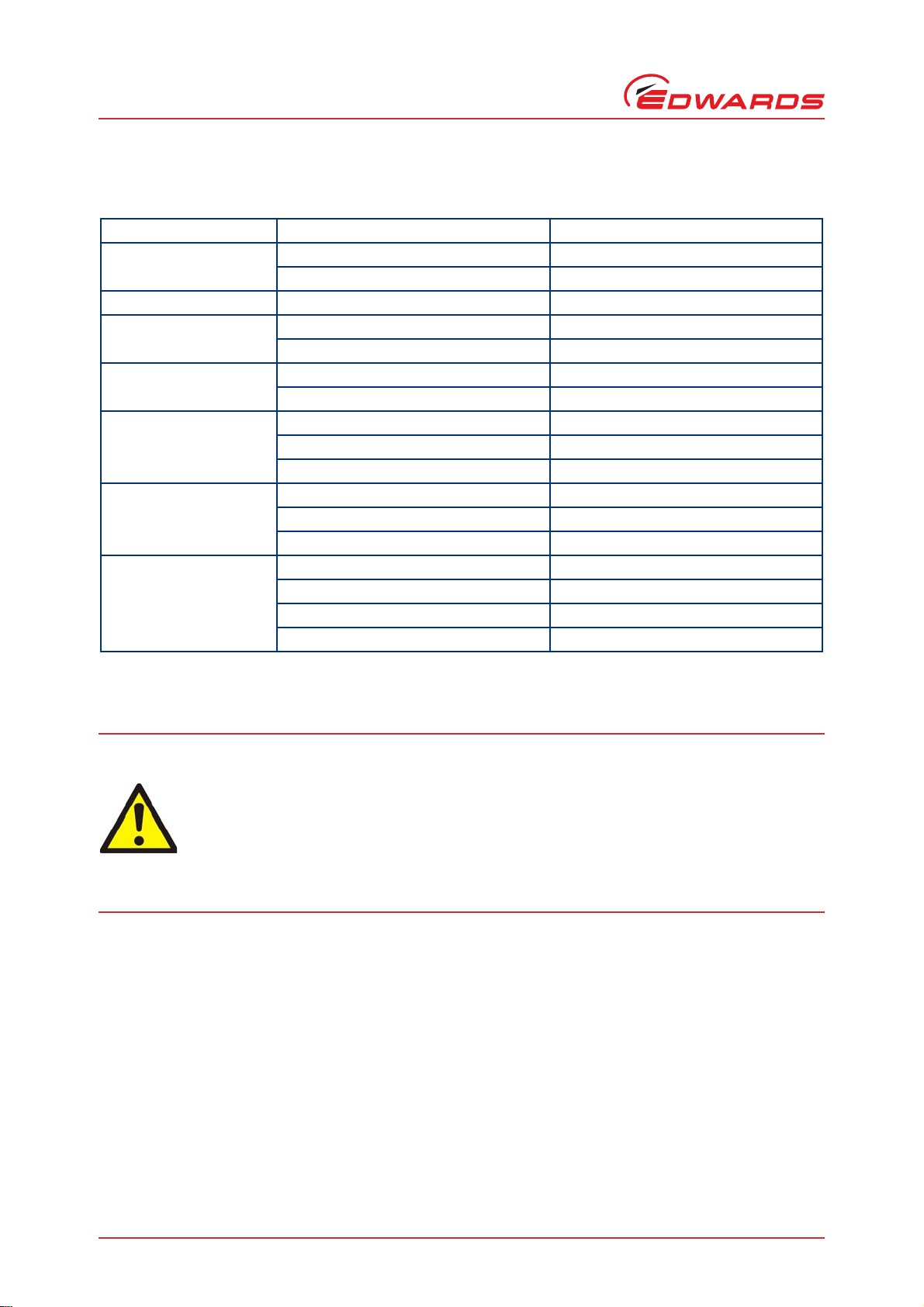
4 Instructions for use
In order to operate the CXS system the mains power supply must be connected to the control box.
The mains power connector and the interface connections must be made using the combination of tested cable glands
and cables listed in Table 4 or by using alternative cables (suitably electrically rated) along with certified Exd
compound glands.
Table 4 - Cable and cable glands for customer connection
Please refer to Figures 3, 4and 5for the type and size of thread.
The installation may only be performed by qualified personnel, which have been suitably trained for this purpose.
All suitable national regulations of the country of use have to be followed.
Any unused entry threads should be sealed with an appropriate Exd rated blanking plug.
4.1 Opening the control box
When opening the control box either by taking off the front lid or one of the cable gland plates or cover plates, you
must ensure that the flame-path surfaces are kept clean and scratch-free. Please refer to Figures 6to 10.
Minimum water supply 4 l/min
Cooling water temperature 5°C - 35°C
Control box Aluminium Alloy AISi7MgKT6
Cable gland plates and lid Aluminium Alloy AW-6082-T6
Where used Tested cable Tested gland
Mains in LAPP 1121377 Hawke, E1WF/25/M25 + Reducer ARB/M32/M25
Customer I/F LAPP 1135762 - 12 way PEPPERS E1WF/16/M20
LAPP 1135762 - 12 way Hawke A501-453-Os-uni
LAPP 1125025 - 25 way PEPPERS E1WF/20s/M20
LAPP 1125025 - 25 way Hawke A501-453-A-uni
LAPP 1135818 - 18 way PEPPERS E1WF/20s/M20
LAPP 0031052 - 16 way x 0.34 Hawke A501-453-A-uni

© Edwards Limited 2018. All rights reserved. Page 5
Edwards and the Edwards logo are trademarks of Edwards Limited.
Instructions for use
P601-01-340 Issue B
Figure 6 - Flame path on control box
Figure 7 - Flame path on lid facing control box
1. 21.3 mm minimum
2. 14 mm minimum
Note: Dimensions in mm

P601-01-340 Issue B
Page 6 © Edwards Limited 2018. All rights reserved.
Edwards and the Edwards logo are trademarks of Edwards Limited.
Instructions for use
Figure 8 - Control box pump facing side safety loom and terminal cover gland plates flame paths
Figure 9 - Safety loom gland plate flame path
Note: Dimensions in mm

© Edwards Limited 2018. All rights reserved. Page 7
Edwards and the Edwards logo are trademarks of Edwards Limited.
Instructions for use
P601-01-340 Issue B
Figure 10 - Terminal cover flame path
1. Unscrew the fasteners on the lid and/or cover/gland plates.
2. Open and remove the lid or plates carefully (the lid is hinged - it is advised not to remove it completely unless
necessary).
3. Store the lid and/or plates in a way to ensure that no damage will be made to the flame-path surfaces.
4. When fitting the lid and/or plates take special care that the flame-paths are not damaged.
5. Tighten the fasteners using the specified tightening torque.
6. Check the gaps between the gland plates and control box and lid and control box to the specification given in
Figure 4.
You must use the fasteners provided with the box or source replacements to the specification below. After
unscrewing the fasteners, keep them in a safe place and ensure they are clean and undamaged if re-using them.
Specification for replacement fasteners:
M8x1.25 6g 12.9 ENP ISO4762
The following table lists the cable/gland combinations that have been tested and approved, for use with the
connections to the CXS system and ancillaries (eg booster pump), in addition to the mains and interface combinations
listed in Section 4.1. These connections will be made by Edwards during the manufacture of the CXS system.
Connections must be made using the following combination of tested cable glands and cables or by using alternative
cables (suitably electrically rated) along with certified Exd compound glands.
WARNING
Any scratches or damage on the flame-path surfaces (refer to Figures 6to 10) will impair the
explosion protection of the CXS Exd control box. Handle all enclosure covers with care. If any
flame-path surface is damaged you must replace that part before re-using the enclosure.
Note: Dimensions in mm

P601-01-340 Issue B
Page 8 © Edwards Limited 2018. All rights reserved.
Edwards and the Edwards logo are trademarks of Edwards Limited.
Instructions for use
List of tested cable glands and cable combinations:
Table 5 - Certified cable glands and cable combinations
* Temperatures at the entry point for the motor cable can be as high as 77°C under rated conditions. If
another cable than the ones listed in Table 5 are chosen, this higher temperature rating has to be taken into
account.
Where used Cable Cable gland
Booster thermistor Lapp 0035004 PEPPERS E1WF/R/16/M20
Lapp 0035004 Hawke A501-453-uni-Os
Booster power Lapp 1121367 - 6mm CY Peppers E1WF/20/M20
Booster N2 supply Lapp 0010000 PEPPERS A3LF/16
Lapp 0010012 Hawke A501-421-A
Sensor cable Lapp 0010012 PEPPERS A3LF/20
Lapp 0010000 Hawke A501-421-Os
Display box interface/ Trip
amp loom/ Cat.2 loom/
PID loom
DEF STAN 61-12, 7-2-25 PEPPERS A3LF/20
DEF STAN 61-12, 7-2-25 Hawke A501-421-A
LAPP 0028051 16 x 0.34 PEPPERS A3LF/20s
CXS Motor power * LAPP 1119614 A3LF/25/M25
LAPP 0011169 A3LF/25/M25
LAPP 1121372 A3LF/25/M25
Solenoid Valve cable Lapp 1119103 PEPPERS A3LF/16
Lapp 1119103 Hawke A501-421-Os
DANFOSS H05 V2v2 -F 3G075 PEPPERS A3LF/16
DANFOSS H05 V2v2 -F 3G075 Hawke A501-421-Os
WARNING
Entries must be fitted with the gland/cable combinations detailed in this manual, or by using
alternative cables (suitably electrically rated) along with certified Exd compound glands,
otherwise the explosion protection can no longer be guaranteed.
All unused entries in the enclosure must be closed using certified Exd blanking/stopping plugs to
guarantee the explosion protection of the control box. If any entries are left open the explosion
protection of the control box can no longer be guaranteed. Refer to Figure 4 for information on
thread type on all entries.

© Edwards Limited 2018. All rights reserved. Page 9
Edwards and the Edwards logo are trademarks of Edwards Limited.
Servicing and Maintenance
P601-01-340 Issue B
5 Servicing and Maintenance
WARNING
Risk of electric shock. Ensure that the power supply to the control box is disconnected before you
start maintenance work.
WARNING
Risk of electric shock. Allow 15 minutes before you open the control box when it has been de-
energised.
WARNING
Risk of damage to equipment or injury to people. Ensure that only suitably trained and authorized
personnel perform work on the control box.

P601-01-340 Issue B
Page 10 © Edwards Limited 2018. All rights reserved.
Edwards and the Edwards logo are trademarks of Edwards Limited.
This page has been intentionally left blank.

This page has been intentionally left blank.

This page has been intentionally left blank.

Return the equipment or components for service
Before you send your equipment to us for service or for any other reason, you must send us a
completed Declaration of Contamination of Vacuum Equipment and Components – Form HS2. The
HS2 form tells us if any substances found in the equipment are hazardous, which is important for
the safety of our employees and all other people involved in the service of your equipment. The
hazard information also lets us select the correct procedures to service your equipment.
We provide instructions for completing the form in the Declaration of Contamination of Vacuum
equipment and Components – Procedure HS1.
If you are returning a vacuum pump, note the following:
If a pump is configured to suit the application, make a record of the configuration before
returning the pump. All replacement pumps will be supplied with default factory settings.
Do not return a pump with accessories fitted. Remove all accessories and retain them for
future use.
The instruction in the returns procedure to drain all fluids does not apply to the lubricant in
pump oil reservoirs.
Download the latest documents from www.edwardsvacuum.com/HSForms/, follow the procedure in
HS1, fill in the electronic HS2 form, print it, sign it, and return the signed copy to Edwards.
Note: If we do not receive a completed HS2 form, we will not accept the return of the
equipment.
P80081000, Issue A

P800‐80‐000IssueT
edwardsvacuum.com
Other manuals for CXS
1
Table of contents
Other Edwards Controllers manuals

Edwards
Edwards AIGX-S-NW25 User manual

Edwards
Edwards EXC120 User manual

Edwards
Edwards D395-92-000 User manual

Edwards
Edwards AIGX-D-NW25 User manual

Edwards
Edwards ASG2-1000-1/8 NPT User manual

Edwards
Edwards PGC202 User manual

Edwards
Edwards iTIM E73/A1/T1 User manual

Edwards
Edwards PGC201 User manual

Edwards
Edwards 4-NET-CAT Assembly instructions

Edwards
Edwards D397-00-000 User manual