eGauge Systems LLC EG30xx User manual

eGauge Model
EG30xx Owner’s Manual
(v1.4)
eGauge Systems LLC
4730 Walnut St, Suite 110
Boulder, CO 80301
http://egauge.net/
877.EGAUGE1
November 3, 2016

EG30xx Owner’s Manual 2 INSTALLATION
1 Introduction
Thank you and congratulations to your purchase of an eGauge device! Properly
installed, the device will be able to record and report energy usage and production
for years to come.
The first and second section of this manual describes installation and commis-
sioning of the product. The third section provides operating instructions and is
followed by a section on equipment maintenance. The appendices provide the
device specifications and a reference to troubleshooting information.
Please visit the eGauge support site to verify you have the latest version of this
manual. There, you can also find additional training materials, tutorial videos,
configuration guide, and CT-selection guides:
http://egauge.net/support/
2 Installation
Installation must be performed by a licensed electrician according to all applicable
local, national, and international codes.
CAUTION: The eGauge power connector carries high voltage. For safety, the
device must be installed in a suitably rated enclosure. The enclosure must have
a screw-on or locking cover that prevents accidental touching of the power
connector or any other metallic parts.
2.1 What’s included in the box
•1×EG30xx device
•1×Power plug (5-position 7.62mm plug)
•0–12×Current transformers (CTs) w/8ft wires & plug (as ordered)
•1×HomePlug AV wall-outlet adapter w/5ft Ethernet cable (if ordered with
an EG301x)
November 3, 2016 2

2 INSTALLATION EG30xx Owner’s Manual
2.2 Materials required for installation
•Per phase: 1×15A circuit breaker or single multi-pole breaker
•Black, red, and white stranded AWG14 wire; length depending on installa-
tion location. Blue wire is needed in addition for 3-phase installations.
•Electrical tape
•Conduit and couplings as needed
•If required, appropriately rated external NEMA enclosure
2.3 Tools required for installation
•#0 slotted screw driver (needed if length of CT-wires needs to be adjusted)
•Circuit-breaker finder (ring-out tool)
•Voltage meter
Additionally, for device commissioning and installation verification:
•Clamp-on AC current meter
•Laptop with Ethernet cable
2.4 Nomenclature and Symbols
In the US, residences typically receive power through split-phase power distribu-
tion which is provided through two hot legs, a neutral, and a protective ground.
Most commercial and industrial buildings receive power through 3-phase power
distribution provided through 3 hot phases, a neutral and protective ground.
Throughout the rest of this document, we use the term “phase” to refer both to the
phases of 3-phase power distribution as well as the two legs used in split-phase
power distribution.
The following table describes the symbols used on the device:
3 November 3, 2016

EG30xx Owner’s Manual 2 INSTALLATION
Symbol: Description:
Caution, risk of danger.
2.4.1 Measurement Category
Measurement Category III is for measurements performed in the building installa-
tion. Examples are measurements on distribution boards, circuit-breakers, wiring,
including cables, bus-bars, junction boxes, switches, socket-outlets in the fixed
installation, and equipment for industrial use and some other equipment, for ex-
ample, stationary motors with permanent connection to the fixed installation.
2.5 Safety Warnings
Please follow the installation instructions in this manual for wiring diagram and
proper selection of CTs.
To reduce the risk of electric shock:
•Do not connect device to a circuit operating at >277 Vrms to neutral.
•Always open or disconnect circuits from Power Distribution System of
building before installing or servicing the unit or attached current trans-
formers.
2.6 Installation Location
The eGauge is usually installed near the power-distribution panel of a building,
where there is easy access to the power circuits to be measured.
The eGauge is permanently connected equipment. A 15A circuit-breaker shall be
included (one per phase) in close proximity of the device and within easy reach
of the operator. The breakers shall be marked as the disconnecting device for
eGauge. The breakers shall be wired to the device in compliance with the NFPA 8
National Electrical Code using a conductor size of at least AWG14.
November 3, 2016 4
2 INSTALLATION EG30xx Owner’s Manual
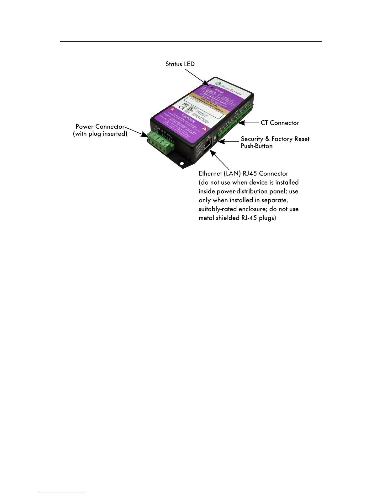
Figure 1: eGauge inputs and outputs
The eGauge is a component and must be installed inside a suitable enclosure. The
enclosure eGauge is installed in must be rated according to the environment it
is used in. For example, outdoor installations require an outdoor-rated enclosure
(e.g., IPX4/NEMA4).
Select an installation location that is not exposed to direct sunlight or the elements.
Otherwise, the warranty may be voided.
Do not install the device in a way that would make it difficult to operate the dis-
connecting device (circuit breakers).
2.7 Device Overview
As shown in Figure 1, the eGauge has two input connectors: the Power Connec-
tor is a 5-pin connector used to wire the device to the building supply. The CT
Connector is used to connect up to 12 current transformers (CTs).
The unit also has an Ethernet port (RJ45 connector) which can be used to hard-
wire the device to a Local Area Network (LAN). However, this port must not
5 November 3, 2016

EG30xx Owner’s Manual 2 INSTALLATION
be used when the device is installed inside a power-distribution panel. In that
case, the port must be covered by the plastic cap that shipped with the unit. The
Ethernet port may be used only when the device is installed in its own, suitably-
rated enclosure exterior to a distribution panel. Shielded RJ-45 plugs must not
be used.
2.7.1 Status LED
The Status LED is an installation aid. When powered on, the LED will briefly
turn yellow, then blue. The blue color indicates that the device is powered up and
recording data.
Green LED
A green LED indicates sufficiently high average speed or signal for the EG30xx’s
specific mode of communication. Note the LED will not turn green if the Ethernet
port is used.
Dark Blue LED
A blue LED indicates low or no speed/signal for the EG30xx’s specific mode of
communication.
Note the eGauge may occasionally switch from green to dark blue, as the signal
quality can vary over time. This is not to be mistaken with alternating to cyan
(light blue).
Blinking on-and-off
An LED that blinks on and off indicates the eGauge is accessible from the Internet
(see Section 4.2).
Alternating to cyan
An LED alternating between dark blue (or green) to cyan every second indicates
the eGauge cannot obtain a DHCP address from the network. A dark blue LED
alternating to cyan can indicate no connection to the network.
Blinking red
An LED blinking red indicates the eGauge is overheating. Let the device cool by
turning it off for a period of time.
For a complete list of Status LED colors and blink patterns, please see the question
“What do the different colors on the Status LED mean?” in the Frequently Asked
Questions Section at:
http://egauge.net/support/
November 3, 2016 6

2 INSTALLATION EG30xx Owner’s Manual
2.7.2 Power Connector
This connector is shown in Figure 2 and the pin-out is as follows:
Pin: Name: Description:
1L1 Wire to phase 1 of building supply.
2NWire to building’s Neutral.
3L2 Wire to phase 2 of building supply for split- and three-phase
installs.
4 Unused. Leave unconnected.
5L3 Wire to phase 3 of building supply for three-phase installs.
Figure 2: Power Connector
The Power Connector is CAT III rated (for measurements performed in the build-
ing installation, such as circuit breakers). Pin L1 serves three purposes: it powers
the device (2W typical, 7.5W maximum), the voltage on the line is measured
to calculate power used/generated on phase L1, and on model EG301x devices it
carries the power-line signal for communicating with the HomePlug AV wall-plug
adapter. The pin must be wired to the building’s power supply with a voltage in
the range from 85–277Vrms (to neutral). In contrast, pins L2 and L3 are used
purely as voltage-taps so power used/generated on phases L2 and L3 can be cal-
culated. Wiring these pins is necessary only if there are CTs measuring current(s)
on L2/L3. The voltage on these lines can be 0-277Vrms (Vac or Vdc). The input
impedance for L2 and L3 is approximately 950kΩat 60Hz. By connecting L2 or
L3 to a DC-voltage, it becomes possible to monitor, for example, the voltage on a
battery backup.
CAUTION: Note that L1, L2, and L3 are all coupled to Neutral. Thus, when
using L2 and/or L3 to monitor, e.g., the voltage on a backup-battery, ensure
that it is safe to wire the other pole of the battery to Neutral (pin N).
7 November 3, 2016

EG30xx Owner’s Manual 2 INSTALLATION
2.7.3 CT Connector
This connector is shown in Figure 3. It provides 12 positions for the CT plugs
illustrated in Figure 7. The silk-screened numbers indicate which CT should be
connected to which pair of pins. Pins that are to receive the black wire of the CTs
are marked with a circle with black interior, pins for the white wires are marked
with a circle with white interior.
The CT Connector is rated for wiring one to twelve units of the CTs listed in
Section B.6. The input voltage rating is 0.333Vrms at the rated current. The input
impedance is approximately 10kΩat 60Hz.
Figure 3: CT Connector
CAUTION: The pins of the CT Connector are at a potential of 2.5V relative
to Neutral (pin Non the Power Connector). Do not connect these pins to any
of the Power Connector pins or the device may be damaged!
NOTE: There is no risk of damage if a CT plug is accidentally inserted such
that it straddles the pins for two different CTs. If this happens, the eGauge will
not be able to measure power properly but otherwise there are no ill effects. To
correct the problem, simply remove and re-insert the plug at the right position.
2.7.4 Ethernet (LAN) Connector
This connector is shown in Figure 4. It provides hard-wired Ethernet connectivity
via an RJ45 plug.
November 3, 2016 8

2 INSTALLATION EG30xx Owner’s Manual
Figure 4: Ethernet Connector
The green LED in the top-left corner of the connector turns on (green) when an
Ethernet cable is plugged in and a valid Ethernet carrier signal has been detected.
The LED goes dark briefly whenever data is being exchanged over the cable. The
yellow LED in the top-right corner of the connectors is a speed indicator. It turns
on (yellow) operating at 100Mbps and is off (dark) when operating at 10Mbps.
CAUTION: For safety-reasons, this port must not be used when the device
is installed inside a power-distribution panel. In that case, the port must be
covered by the plastic cap that shipped with the unit. The Ethernet port may
be used only when the device is installed in its own, suitably-rated enclosure.
CAUTION: Shielded RJ-45 plugs should not be used when connecting via
Ethernet to the eGauge, as a fault can occur by creating a ground fault between
the eGauge Ethernet sheathing and a switch or hub’s power system.
2.7.5 Push Button
Figure 5 is a close-up of the push-button hole (below the lock symbol). Use a
standard 0.8mm paper clip to activate the push-button located directly behind the
hole.
The push button can be used to (a) setup HomePlug AV encryption for model
EG301x devices, (b) to reset the device to factory defaults. The function per-
formed depends on the length of time that the button is being pushed:
9 November 3, 2016
EG30xx Owner’s Manual 2 INSTALLATION
Figure 5: Push Button Hole
Push Duration: Status LED: Description:
0.5 – 3 sec rapidly blinks
blue & black
Join mode: device will attempt
to join an existing HomePlug AV
network.
13 – 16 sec rapidly blinks
red & blue
Leave mode: device randomizes
its HomePlug AV encryption key
thus leaving any networks it may
have been a member of.
20 – 30 sec rapidly blinks
red & green
Factory reset: device restores
itself to factory defaults.
Between the durations listed in the table, the Status LED will be solid green,
indicating that it is safe to release the push button without causing any action. A
solid red Status LED indicates the current action is unavailable.
2.7.6 Time Reference
During normal operation, the eGauge maintains accurate time by synchronizing
with an NTP server, such as one of the public servers available at ntp.org. Since
NTP provides atomic-clock accuracy, there is usually no need to set the time man-
ually.
When the NTP server is not accessible, either temporarily (e.g., after a power
failure) or permanently (e.g., at a remote site), the eGauge relies on a battery-
backed real-time clock to maintain proper time.
The battery backup is designed only to cover relatively short power outages.
Specifically, after a week of charging, the battery is able to maintain proper time
for about one day. It takes about two months to fully charge the battery and, once
fully charged, the battery is able to maintain proper time for about a week. Should
the eGauge remain without power for longer than that, proper time will be lost.
November 3, 2016 10

2 INSTALLATION EG30xx Owner’s Manual
When power is restored after such an event, the eGauge will attempt to restore
proper time via the NTP server. If unavailable, the device will fall back to using
the time that was in effect when the last data item was recorded prior to the power
failure. The proper time must then be restored later on, either manually via the
device’s Settings→Date & Time page or by provisioning an NTP server that is
accessible.
2.8 Wiring Diagram
2.8.1 Typical Residential (Split-Phase) Installation
Figure 6 is a schematic wiring diagram showing a typical split-phase installation
where the eGauge is used to measure the amount of power being supplied by the
power utility (CTs 1–2) and the power supplied by a single-phase solar inverter
(CT 3). For simplicity, circuit-breakers are not shown.
Figure 6: Wiring Diagram for a Typical Split-Phase Installation
2.8.2 Other Installations
For commercial three-phase installation as well as many other installation and
configuration-scenarios, please refer to the Configuration Guide, available at:
http://egauge.net/support/
11 November 3, 2016

EG30xx Owner’s Manual 2 INSTALLATION
2.9 Installation steps
1. If you are planning on using the hard-wired Ethernet port, skip to Step 3 (use
of communication other than HomePlug requires installation in a separate
enclosure). Otherwise, you are planning on using the built-in HomePlug AV
power-line available with model EG301x devices:
(a) Find a spot at the installation site that has both an available power
outlet and a nearby Ethernet port (for access to the LAN).
(b) Plug the HomePlug AV adapter into the outlet.
(c) Connect the HomePlug AV adapter to the Ethernet port with the sup-
plied Ethernet cable.
2. Use a circuit-breaker-finder to locate the breaker for the outlet into which
the HomePlug AV adapter is plugged into. Designate the breaker’s phase
as L1. In split-phase installations, label the other phase L2. In 3-phase
installations, label the other two phases L2 and L3 (order does not matter,
as long as the labeling is applied consistently throughout the installation).
3. Install the new breaker(s) in the power-distribution panel such that they pro-
vide access to all phases.
4. Open the breakers so there is no power on the breaker contacts.
5. Mount the eGauge either inside the power-distribution panel (if permitted,
space is available, and Ethernet port is not being used) or inside a suitable
enclosure near the power distribution panel.
6. Wire the 5-position plug as follows:
(a) Black wire: pin labeled L1 to breaker for phase L1.
(b) White wire: pin labeled Nto Neutral.
(c) Red wire: pin labeled L2 to breaker for phase L2.
(d) Blue wire: pin labeled L3 to breaker for phase L3 (3-phase installa-
tions only).
7. Insert the 2-pin CT plugs into the CT Connector on the eGauge and record
the amperage of the CT, the phase being measured, and the item being mea-
sured in the table in Appendix D.
November 3, 2016 12

2 INSTALLATION EG30xx Owner’s Manual
Figure 7: Correct wiring for 2-pin CT plug
NOTE: Ensure that the stickers on the CTs point towards what is being
measured.
If it is necessary to shorten or lengthen the CT wires, ensure that the CT
wires are connected as shown in Figure 7.
8. Close the newly installed breakers. This should cause the eGauge to power
up and, within a few seconds, the Status LED should turn blue. The LED
will turn green if good signal with the HomePlug adapter or wireless net-
work is established (the EG300x Status LED will never turn green). The
LED will start to blink when the device is connected to d.egauge.net.
At that point, it can be found at http://egauge.net/devices/. For
this to work, the device needs to be able to make an outgoing TCP connec-
tion to port 8082 of host d.egauge.net.
9. Label the newly installed breakers as “eGauge Disconnect” so the cus-
tomer can readily find them if it becomes necessary to power-cycle or turn
off the eGauge device for any reason.
IMPORTANT: Labeling the breaker(s) is essential. Do not skip that step.
Occasionally, it may be necessary to power-cycle the device. The breaker(s)
provide the only safe way to do that, so for safety-reasons, it is important that
the end-customer is able to identify the eGauge breaker(s) without having to
open any enclosures.
13 November 3, 2016

EG30xx Owner’s Manual 3 COMMISSIONING
3 Commissioning
After installation, it is essential to verify that the device is operating properly and
measuring the expected quantities. Each device ships with a default configuration
that may or may not match your installation situation. In general, it is therefore
necessary to adjust the settings to match your situation. Please see the Configura-
tion Guide for details (available at http://egauge.net/support/).
For revenue-grade accuracy compliance, the eGauge must be paired with revenue-
grade CTs tested and supported by eGauge. Please contact eGauge Systems for
details.
Use a laptop or another computer to connect to the device’s built-in web-server
(see next section). Then, as described in the Configuration Guide, Tools→Chan-
nel Checker can be used to confirm that:
1. All voltages have the expected values (use voltage meter to verify).
2. All CTs report the expected currents (use clamp-on current meter to verify).
3. CTs are indeed installed on the phases set under Settings→Installation.
The voltage between the wire that the CT is clamped onto and the power-
plug pin (L1-L3) that corresponds to the phase it is configured for should
be zero Volts.
4. All reported power values have expected polarity and power-factors. As a
general rule, eGauge convention requires that power coming into the site
shows as positive values and power being consumed at or diverted from the
site shows as negative values.
Also confirm that the eGauge dash-board shows a red line for total consumption.
Assuming all power coming into a site is measured by the device, this line should
never dip into the negative. As a final check, it is helpful to turn on and off some
large loads to confirm everything operates as expected. If there is a renewable
energy system on site, turning it on/off should not appreciably affect the red line
(total consumption).
November 3, 2016 14
4 OPERATION EG30xx Owner’s Manual
4 Operation
4.1 Accessing your eGauge for the first time
Once the eGauge is installed, you can access it from any computer on your Local
Area Network (LAN) with a compatible web-browser (see spec-sheet). To start,
enter the following Web address into your web-browser:
Microsoft Windows: http://devname/
All other computers: http://devname.local/
where devname is the name of the device (e.g., eGauge9999). For example,
to access device eGauge9999, you would enter the following URL into your
browser:
Microsoft Windows: http://egauge9999/
All other computers: http://egauge9999.local/
NOTE: If you wish to use the .local names on Microsoft Windows com-
puters, it is necessary to install Apple’s Bonjour technology. This technology
can be downloaded and installed free of charge from the following URL:
http://support.apple.com/kb/DL999
An example of the eGauge dashboard can be seen in Figure 8. Tutorials for us-
ing the dashboard are available at http://egauge.net/support/. Online
help is available via the Help link at the top-right of the dashboard.
4.2 Accessing your eGauge from the Internet
To access the eGauge from the Internet, open a compatible web-browser and then
visit the Web page at: http://egauge.net/devices/.
Type the name of your device into the search box on that page (or any unique part
of it) and then click on the the matching entry.
15 November 3, 2016

EG30xx Owner’s Manual 4 OPERATION
Figure 8: eGauge dashboard
November 3, 2016 16

4 OPERATION EG30xx Owner’s Manual
Alternatively, you can directly enter the following web address into your browser:
http://devname.egaug.es/ where devname is the name of your device
(e.g., “eGauge9999”).
You can also use the above URL as an alternative means to connect to your device
directly through your LAN. To accomplish that, click on the LAN Access link on
the top right of the page, once the device’s dashboard has loaded. This directs
your browser to access the device directly (through your LAN rather than going
through egauge.net). This is both faster and allows you to access the device
even at times when your Internet-connection may not be working properly. Please
bookmark the address displayed in the browser after the page referred to by the
LAN Access link has finished loading.
NOTE: From time to time, the address of your eGauge may change and the
bookmark will stop working. Should this happen, repeat the above steps and
update the bookmark with the new address. Usually, this happens infrequently,
if at all. However, since it can happen, we recommend using the connection-
methods described in the previous section whenever possible. Alternatively, a
static (fixed) address can be configured for the device. See the next section for
details.
The eGauge proxy service is best-effort and not guaranteed to be available at all
times. See the Proxy Server Statement on http://www.egauge.net/policy/ for more
details.
4.3 Configuring a Static IP Address
The eGauge normally automatically obtains its IP address and associated infor-
mation through a service called Dynamic Host Configuration Protocol (DHCP). If
you cannot or do not wish to run this service on your LAN, the device will default
to using IP address 192.168.1.88, so the device can be accessed as:
http://192.168.1.88/
Your computer’s IP address must be configured to be on the same range as this
default address. If another device ends up using the same address, or a static IP
address is required, you may configure one from Settings→Network Settings.
17 November 3, 2016

EG30xx Owner’s Manual 5 MAINTENANCE
Please visit http://egauge.net/support and check the Documents sec-
tion for additional documentation on connecting directly to an eGauge and assign-
ing a static IP address.
4.4 Verifying the Proper Time
When the Internet is not available to the eGauge, it may be necessary to set the date
and time manually. To verify that the eGauge has the proper time, use a browser
to go to the device’s dashboard (see previous sections), then click on Settings,
then on Date & Time. If the displayed date and/or time is wrong, please enter the
correct values and then click on Save. Please repeat this step from time to time,
especially after prolonged power outages lasting more than a few hours.
4.5 Passwords and Saving Settings
By default, changes may be made using user-name owner and password default.
You must connect to the eGauge directly over the local network before making
changes. This can be accomplished by clicking the LAN Access link in the upper-
right hand menu on the eGauge main interface. Credentials and remote adminis-
tration can be managed in Settings→Access Control.
5 Maintenance
The eGauge is designed to be maintenance free. No preventive maintenance or
inspections are required.
Should it become necessary to clean the eGauge, disconnect it from the building
supply by turning off the breakers labeled “eGauge Disconnect”, remove the
device, and clean it with a soft cloth. If a cleaning fluid is needed, use 70%
isopropyl alcohol. Wait until all cleaning fluid has evaporated before reinstalling
the device and turning the breakers back on.
The device has no replaceable batteries and no replaceable fuses.
November 3, 2016 18

A FCC COMPLIANCE EG30xx Owner’s Manual
A FCC Compliance
A.1 Compliance Statement
This equipment has been tested and found to comply with the limits for a Class B
digital device, pursuant to part 15 of the FCC Rules. These limits are designed to
provide reasonable protection against harmful interference in a residential installa-
tion. This equipment generates, uses and can radiate radio frequency energy and,
if not installed and used in accordance with the instructions, may cause harmful
interference to radio communications. However, there is no guarantee that inter-
ference will not occur in a particular installation. If this equipment does cause
harmful interference to radio or television reception, which can be determined
by turning the equipment off and on, the user is encouraged to try to correct the
interference by one or more of the following measures:
•Reorient or relocate the receiving antenna.
•Increase the separation between the equipment and receiver.
•Connect the equipment into an outlet on a circuit different from that to
which the receiver is connected.
•Consult the dealer or an experienced radio/TV technician for help.
A.2 Radiation Exposure Statement
This equipment complies with FCC radiation exposure set for an uncontrolled en-
vironment. In order to avoid the possibility of exceeding the FCC radio frequency
exposure limits, human proximity to the antenna shall not be less than 20cm dur-
ing normal operation. Antenna(s) used with this transmitter must not be used in
conjunction or co-located with any other transmitter or antenna.
CAUTION: Changes or modifications to the equipment not expressly ap-
proved by eGauge Systems LLC could void the user’s authority to operate the
equipment.
19 November 3, 2016

EG30xx Owner’s Manual B SPECIFICATIONS
B Specifications
B.1 Applicable Model Numbers
This manual applies to all eGauge models ranging from EG3000 through EG3099.
B.2 Electrical Rating of the Product
85-277Vrms, 1-3 phases, 50-60 Hz, 7.5W peak (2W typical).
B.3 Environmental Conditions
Suitable for indoor and outdoor use (with proper enclosure), Pollution Degree 2,
Measurement Category III. Not to be used at altitudes above 4000m. Voltage
fluctuations not to exceed ±10%. Temperature range: -30–70◦C (-22–158◦F).
Maximum relative humidity 80% up to 31◦C, decreasing linearly to 50% at 40◦C.
B.4 CE Immunity Statement
Performance criteria: At field-strengths up to 10V/m, no change of state or stored
data, may exhibit temporary variation in analogue input values.
B.5 Regulatory Certificates
Listed device under IEC 61010-1 (2004 edition)
CAN/CSA-C22.2 No. 61010-1
FCC 47CFR Part 15 Class B
CISPR 16-1, EN55024, EN61000-4, ENV 50204
RCM
The eGauge system is a Listed Device, certified to be used with CTs with the following
specifications: UR and CSA, 0.333Vrms output at rated current, and 600V insulation.
November 3, 2016 20
This manual suits for next models
1
Table of contents
Other eGauge Systems LLC Data Logger manuals


