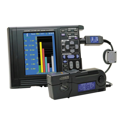
Hioki HiLogger 3145-20 User manual

3145-20 Instruction Manual
NOISE HiLOGGER
3145-20
NOISE HiLOGGER
April 2013 Revised edition 5 3145A981-05 13-04H
Instruction Manual
Contains explanation and
instructions regarding the
3145-20 NOISE HiLOGGER’s
operating method and functions.


Contents
i
1
2
3
4
5
6
7
8
9
A
Index
Contents
Introduction.................................................................................1
Verifying Package Contents.......................................................2
Safety Information ......................................................................3
Operating Precautions................................................................5
Chapter 1 Overview__________________________ 7
1.1 Product Overview .........................................................7
1.2 Features .......................................................................8
1.3 Measuring Principle ......................................................9
1.3.1 Monitor Measuring and Logging Measuring ...........10
1.3.2 Merits of the Measurement Method of this
Instrument ...............................................................11
1.4 Names and Functions of Parts ...................................12
1.5 Display Screen ...........................................................16
1.5.1 Screen Layout .........................................................16
1.5.2 Logging Screen .......................................................17
1.5.3 Monitor Screen .......................................................20
1.5.4 Icon Summary .........................................................22
1.5.5 Submenus ...............................................................24
Chapter 2 Measurement Preparations _____25
2.1 Attaching the Strap .....................................................26
2.2 Install the Ferrite Cores ..............................................27
2.3 Connecting the AC Adapter .......................................28
2.4 Supplying Power with the Battery Pack .....................29
2.4.1 Installing the Battery Pack ......................................29
2.4.2 Charging the Battery Pack ......................................30
2.4.3 Battery Pack Life .....................................................32
2.5 Connect the CLAMP ON NOISE SENSOR ................33
2.6 Turning the Power On and Off ...................................36
2.7 Using the PC Card .....................................................37
2.7.1 Inserting the PC card ..............................................37
2.7.2 PC Card Initialization ..............................................38
2.8 Pre-Operation Inspection ...........................................40

Contents
ii
Chapter 3 Measurement____________________ 41
3.1 The Measurement Process ....................................... 42
3.2 Check the Current Input (Monitor Measurement) ...... 43
3.3 Record Changes Over Time (Logging Measurement) 45
3.4 "O.F." Display and "U.F." Display .............................. 50
Chapter 4 Useful Functions ________________ 51
4.1 View the Latest Logging Measurement Value or
Peak Value ................................................................ 52
4.2 Check Using a Bar Graph (Monitor Measurement) ... 52
4.3 View Past Waveforms (Scroll Function) .................... 53
4.3.1 Scrolling the Waveform ..........................................53
4.3.2 Auto Scrolling .........................................................54
4.4 A/B Cursor Measurement .......................................... 55
4.5 Using the Alarm Function .......................................... 56
4.5.1 Settings on the Logging Screen or the
Monitor Screen. ......................................................56
4.5.2 Setting on the Set Up Screen .................................59
4.5.3 Take the Alarm Reference Value (Monitor Screen) 65
4.6 Adding Event Marks to Waveforms ........................... 66
4.6.1 How to Add an Event Mark .....................................66
4.6.2 Searching Event Marks ..........................................67
4.7 Highlighting a Specific Band ...................................... 68
4.8 Preventing Malfunctions (Key Lock) .......................... 69
4.9 Saving the Display Screen to PC Card
(Screen Capture) 70
Chapter 5
Setting the Measurement Conditions______ 71
5.1 Inputting Comments .................................................. 72
5.1.1 Comment Input Method Details ..............................73
5.2 Setting the Input Type ............................................... 74
5.3 Setting the Range ...................................................... 75
5.4 Setting the Recording Interval ................................... 76
5.5 Setting the Recording Time ....................................... 77
5.6 Setting the Waveform Color ...................................... 79

Contents
iii
1
2
3
4
5
6
7
8
9
A
Index
Chapter 6 Saving and Reading Data________81
6.1 Saving Data during Measurement ..............................82
6.1.1 Select "3145 Form" .................................................82
6.1.2 Filenames ...............................................................83
6.1.3 Save Mode ..............................................................84
6.1.4 Specify the File Save Target ...................................89
6.2 Planning to Save Text after Measurement .................90
6.3 Saving Data after Measurement ................................91
6.4 Saving Settings Data ..................................................94
6.5 Reading Measurement and Settings Data .................97
6.6 File Operation .............................................................99
6.6.1 Moving between Folders .......................................100
6.6.2 Deleting Files and Folders ....................................101
6.6.3 Creating Folders ...................................................102
6.6.4 Changing File Names and Folder Names .............104
6.6.5 Changing the File Order .......................................105
6.7 Calculation Method for “3145 Form” Files ................106
6.8 Content Format for Text Format Files ......................107
Chapter 7 System Screen_________________ 109
7.1 Env (Environment) Screen .......................................110
7.1.1 Start Key Receive Condition
(Malfunction Prevention) 110
7.1.2 Start Backup After Power Loss .............................111
7.1.3 Grid Type ..............................................................112
7.1.4 Time Format when Saving Text ............................113
7.1.5 External Trigger Input (Event Marker) ..................114
7.1.6 External Trigger Filter ...........................................115
7.1.7 Copy Key Function (Monitor) ................................116
7.1.8 Save Color ............................................................117
7.1.9 Backlight Saver .....................................................118
7.1.10Backlight Brightness .............................................119
7.1.11Screen Color Scheme ...........................................120
7.1.12Display Language .................................................121
7.2 Setting Screen ..........................................................122
7.2.1 Saving Settings .....................................................122
7.2.2 Loading Setting Conditions ...................................124
7.2.3 Deleting Setting Conditions ..................................125
7.2.4 Automatically Loading ...........................................126
Contents
iv
7.2.5 Auto Setup ............................................................126
7.3 Init (Initialization) Screen ......................................... 127
7.3.1 Setting the Clock ..................................................127
7.3.2 Erasing Logging Measurement Data ....................128
7.3.3 System Reset .......................................................129
7.3.4 Self-check .............................................................130
Chapter 8 Using the CD ___________________131
8.1 CD Contents ............................................................ 131
8.2 Installing the Software ............................................. 132
8.3 Running the Software .............................................. 133
8.4 Deleting the Application (Uninstall) .......................... 134
8.5 Opening the Instruction Manual (PDF Format) ........ 135
Chapter 9 Specifications__________________137
9.1 General Specifications ............................................. 137
9.2 Input Area Specifications ......................................... 140
9.3 Accuracy .................................................................. 142
9.4 Function Specifications ............................................ 143
9.5 Application Software Specifications ......................... 146
Chapter 10 Maintenance and Service_____147
10.1 Troubleshooting ....................................................... 148
10.1.1Before Returning for Repair ..................................148
10.1.2System Reset .......................................................149
10.2 Warning Messages .................................................. 150
10.3 Cleaning .................................................................. 152
10.4 Replacing the Backup Battery ................................. 153
10.5 Removing the Battery Before Discarding the
Instrument 154
Appendix____________________________________ A1
Appendix 1 The Carrying Case ......................................................A1
Appendix 2 Trigger Terminals ........................................................A2
Appendix 2.1EXT TRIG Terminal .............................................A2
Appendix 2.2TRIG OUT Terminal .............................................A5
Appendix 3 Glossary of Terms.......................................................A7

Introduction
1
Thank you for purchasing the HIOKI "Model 3145-20 NOISE HiLOG-
GER." To obtain maximum performance from the instrument, please
read this manual first, and keep it handy for future reference.
The following instruction manuals are included with the 3145-20 NOISE
HiLOGGER. Refer to them as they pertain to your usage of the instru-
ment.
Use the optional Clamp on Noise Sensor for measuring current. Read
the instruction manual included with the Clamp on Noise Sensor and fol-
low all safety precautions.
User's License The "DATA VIEWER for 3145" software is included with the instrument.
This software requires a license agreement. Please use it only after
reading and accepting the license agreement at the back of the book.
Registered
Trademarks Windows, Microsoft Excel, and MS-DOS are registered trademarks of
Microsoft Corporation in the United States and/or other countries.
Introduction
Manuals Contents
1Measurement Guide
Read first.
Offers an introduction to the 3145-
20's basic measuring method for first
time users.
2Instruction Manual
(this manual)
Contains explanation and instructions
regarding the instrument's operating
method and functions.
CD Contents
3"DATA VIEWER for
3145"
Instruction Manual
Contains information about PC soft-
ware which can analyze the measure-
ment data recorded by the
instrument.
4"Communications"
Instruction Manual
Explainsthecommunicationfunctions
which can be used via the LAN and
RS-232C interfaces.
5"Communication
Commands"
Instruction Manual
Explains the commands for remote
control of the instrument via the LAN
and RS-232C interfaces.

Verifying Package Contents
2
• When you receive the instrument, inspect it carefully to ensure that no damage occurred
during shipping. In particular, check the accessories, panel switches, and connectors. If
damage is evident, or if it fails to operate according to the specifications, contact your
dealer or Hioki representative.
• Use the original packing materials when transporting the instrument, if possible.
Please check to make sure that no items are missing from your package.
Options Model 9754 CLAMP ON NOISE SENSOR
Model 9418-15 AC ADAPTER
Model 9447 BATTERY PACK (7.2 V, 2400 mAh)
Model 9643 CHARGE STAND (For the 9447 BATTERY PACK)
Model 9612 RS-232C CABLE
(9-pin mini DIN to 9-pin Dsub, cross cable, for PC)
Model 9721 RS-232C CABLE
(9-pin mini DIN to 9-pin Dsub, straight cable, for modem)
Model 9726 PC CARD 128M
Model 9727 PC CARD 256M
Model 9728 PC CARD 512M
Model 9729 PC CARD 1G
Model 9642 LAN CABLE
Verifying Package Contents
Carrying case........................................1
Strap......................................................1
CD (Software, Instruction Manuals)
...................................................................1
Instruction Manual (this manual)/
Measurement Guide..................each one
• "DATA VIEWER for 3145"
Software and Instruction Manual
• "Communications”
Instruction Manual
• "Communication Commands"
Instruction Manual
Model 3145-20 NOISE HiLOGGER ......1
Accessories
Model 9418-15 AC ADAPTER..............1
Ferrite cores..........................................3

Safety Information
3
Safety
Symbols This manual contains information and warnings essential for safe opera-
tion of the instrument and for maintaining it in safe operating condition.
Before using it, be sure to carefully read the following safety precautions.
The following symbols in this manual indicate the relative importance of
cautions and warnings.
Safety Information
This instrument is designed to comply with IEC 61010 Safety Stan-
dards, and has been thoroughly tested for safety prior to ship-
ment. However, mishandling during use could result in injury or
death, as well as damage to the instrument. Using the instrument
in a way not described in this manual may negate the provided
safety features.
Be certain that you understand the instructions and precautions in
the manual before use. We disclaim any responsibility for acci-
dents or injuries not resulting directly from instrument defects.
Notation
In the manual, the symbol indicates particularly impor-
tant information that the user should read before using
the instrument.
The symbol printed on the instrument indicates that
the user should refer to a corresponding topic in the man-
ual (marked with the symbol) before using the relevant
function.
Indicates a grounding terminal.
Indicates DC (Direct Current).
Indicates the ON side of the power switch.
Indicates the OFF side of the power switch.
Indicates that incorrect operation presents an extreme
hazard that could result in serious injury or death to the
user.
Indicates that incorrect operation presents a significant
hazard that could result in serious injury or death to the
user.
Indicates that incorrect operation presents a possibility of
injury to the user or damage to the instrument.
Indicates advisory items related to performance or correct
operation of the instrument.

Safety Information
4
Others
Accuracy We define measurement tolerances in terms of rdg. (reading) value, with
the following meanings:
rdg. (reading or displayed value)
The value currently being measured and indicated on the measuring
instrument.
To ensure safe operation of measurement instrument, IEC 61010 establishes safety stan-
dards for various electrical environments, categorized as CAT II to CAT IV, and called mea-
surement categories.
Using a measurement instrument in an envi-
ronment designated with a higher-numbered
category than that for which the instrument is
rated could result in a severe accident, and
must be carefully avoided.
Use of a measurement instrument that is not
CAT-rated in CAT II to CAT IV measurement
applications could result in a severe accident,
and must be carefully avoided.
Indicates a prohibited action.
p Indicates the location of reference information.
Indicates quick references for operation and remedies for
troubleshooting.
*Indicates that descriptive information is provided below.
Measurement categories
CAT II Primary electrical circuits in equipment connected to an AC electrical
outlet by a power cord (portable tools, household appliances, etc.)
CAT II covers directly measuring electrical outlet receptacles.
CAT III Primary electrical circuits of heavy equipment (fixed installations) con-
nected directly to the distribution panel, and feeders from the distribution
panel to outlets.
CAT IV The circuit from the service drop to the service entrance, and to the power
meter and primary overcurrent protection instrument (distribution panel).

Operating Precautions
5
Follow these precautions to ensure safe operation and to obtain the full benefits of the vari-
ous functions.
Before using the instrument the first time, verify that it operates normally to ensure that the
no damage occurred during storage or shipping. If you find any damage, contact your
dealer or Hioki representative.
Operating temperature & humidity: 0 to 40°C (32 to 104°F), 80%RH or less (non-condensating)
Operating temperature & humidity for guaranteed accuracy: 23 ± 5°C (73 ± 9°F), 80%RH or less
Operating Precautions
Preliminary checks
Before using the instrument, make sure that the insulation on the
test leads is undamaged and that no bare conductors are improp-
erly exposed. Using the instrument in such conditions could
cause an electric shock, so contact your dealer or Hioki represen-
tative for repair.
Installing the instrument
Avoid the following locations that could cause an accident or damage to the instrument.
Exposed to direct sunlight
Exposed to high tempera-
ture
In the presence of corro-
sive or explosive gases
Exposed to liquids
Exposed to high humidity
or condensation
Exposed to strong electro-
magnetic fields
Near electromagnetic radi-
ators
Exposed to high levels of
particulate dust Subject to vibration
Installing the instrument
• Vents must not be obstructed.
• The instrument should be operated
only with the bottom side downwards.
• Do not place on an unstable stand or
on an incline.
10 cm or more
Ventilation holes

Operating Precautions
6
Handling the instrument
To avoid electric shock, do not remove the instrument's case. The
internal components of the instrument carry high voltages and
may become very hot during operation.
To avoid damage to the instrument, protect it from physical shock when
transporting and handling. Be especially careful to avoid physical shock
from dropping.
To avoid problems with battery operation, remove the batteries from the
instrument if it is to be stored for a long time.
Handling the CD
• Always hold the disc by the edges, so as not to make fingerprints on
the disc or scratch the printing.
• Never touch the recorded side of the disc. Do not place the disc
directly on anything hard.
• Do not wet the disc with volatile alcohol or water, as there is a possibil-
ity of the label printing disappearing.
• To write on the disc label surface, use a spirit-based felt pen. Do not
use a ball-point pen or hard-tipped pen, because there is a danger of
scratching the surface and corrupting the data. Do not use adhesive
labels.
• Do not expose the disc directly to the sun's rays, or keep it in condi-
tions of high temperature or humidity, as there is a danger of warping,
with consequent loss of data.
• To remove dirt, dust, or fingerprints from the disc, wipe with a dry
cloth, or use a CD cleaner. Always wipe radially from the inside to the
outside, and do no wipe with circular movements. Never use abra-
sives or solvent cleaners.
• Hioki shall not be held liable for any problems with a computer system
that arises from the use of this CD, or for any problem related to the
purchase of a Hioki product.

1.1 Product Overview
7
1
Chapter 1 Overview
The 3145-20 NOISE HiLOGGER is the ideal measuring instrument for
measuring current on lines which can easily become channels for noise
penetration, such as communication lines, electric power cords and
ground lines which connect to electronic equipment.
By clamping with the 9754 CLAMP ON NOISE SENSOR the 3145-20
detects noise without touching the sample. Therefore it can perform
measurements on instruments in their normal operational state, without
worry of communication malfunction due to probe contact, or electrical
shock or electrical short circuit accidents from electrical lines. Further-
more, it can reliably detect sudden surges which may occur unexpect-
edly, such as thunder surges and open-close surges.
With the use of the logging function, long term or cyclic noise level fluctu-
ations can be understood. Recorded data is shown on the instrument's
color LCD display as a chronological graph. Additionally, transferring
data to a PC and checking the chronological graph can be done using
the "DATA VIEWER for 3145" software on the included CD. This can be
useful for examining noise counter-measures after an occurance of
noise interference.
Overview Chapter 1
1.1 Product Overview
Communication
lines
Electrical
lines Ground
lines

1.2 Features
8
1.2 Features
Simple and safe measurements
With the use of the optional Clamp on Noise Sensor, noise can be measured on
power cords, various communications lines, and ground lines without making con-
tact or grounding.
Wide frequency range (5 kHz - 100 MHz)
The instrument is effective for detecting switching regulator noise, inverter noise,
electrostatic discharge noise, and FM broadcast wave noise.
Surge detection
The instrument detects lightning surges, power-related switching surges, and
electrostatic discharge noise.
Logging measurement function
Long-term and cyclic noise levels can be ascertained, and the times at which the
noise and interference occured can be investigated.
Alarm function and event mark function
An alarm level for alarm output can be set, and event marking can be enacted at
the time an event occurs.
Remote measuring with an HTTP server
Remote control of the instrument's settings, data acquisition and data display can
be performed using a web-based browser such as IE.
A portable, dedicated noise measurement instrument intended for on-
site use
The instrument supports two types of power sources, recharchable batteries
designed for on-site use, and an AC adaptor power supply for long period obser-
vation and remote measuring. The recharchable battery can also be used as a
backup in case of power failure.

1.3 Measuring Principle
9
1
Chapter 1 Overview
The instrument separates input noise waves into frequency bandwidths using a seven
band-pass filter (7 frequency waves) and detects and displays peak values (Peak to Peak
values) for each respective frequency range.
1.3 Measuring Principle
-3dB
Q=fo/B=1
15kHz 70kHz 250kHz 1MHz 5MHz 20MHz 60MHz
-40dB/dec
Center frequency f0
Attenuation property
Frequency
Band width B
Amplification
15kHz 70kHz250kHz1MHz 60MHz20MHz
5MHz
f0= 15 kHz
f1= 70 kHz
f2= 250 kHz
f3= 1 MHz
f4= 5 MHz
f5= 20 MHz
f6= 60 MHz
Sampling time Measurement
values at each
band
Measures and displays Peak to Peak
values during sampling time at each
PBF.
Peak to Peak value
within sampling time
Peak to Peak value
within sampling time

1.3 Measuring Principle
10
This instrument has two measuring modes, monitor and logging.
Monitor measurement
Logging measurement
1.3.1 Monitor Measuring and Logging Measuring
The current input levels of each frequency are displayed
as a bar graph and numbers.
Noise measurement can be made easily in the tester in-
terval.
With the logging measurement function the change over
time of the noise level of each frequency band is record-
ed. When and at what frequency band
noisepenetratedcan beeasilyascertained. Thetime that
the interference occured and the type of noise that oc-
cured at that time can be understood.
The peak value within the manually set recording interval
segmentis savedin theinternalmemory anddisplayed in
a chronological bar graph. The recording interval can be
set between 1 second and 60 seconds.
Measurement data can be saved on PC card.
Daily and weekly changes in the noise can beob-
served using the "DATA VIEWER for 3145" soft-
ware on the included CD to conduct daily and
weekly calculation displays of the recorded data.

1.3 Measuring Principle
11
1
Chapter 1 Overview
Simultaneous noise measurement of each frequency bandwidth from 10 kHz
to 100 MHz.
Noise exists in a wide bandwidth and its frequency differs depending on
its cause. With this instrument a wide bandwidth of noise can be
checked all at once.
Peak-detection function for capturing surge events
Surge incidents of noise such as lightning surges and electrostatic dis-
charge noise sometimes occur. Using the instrument's peak function,
incidents of surge noise can be accurately captured.
1.3.2 Merits of the Measurement Method of this
Instrument
Electrostatic discharge
Electric railway induction
Flourescent light Motor for power Arc-welding machine
Medium wave radio
Lightning surge
Switching
Neon sign Elevator
The 3145-20 possible
measurement range
1G
100M
10M
1M
100k
10k
1k
The cause of the noise
Frequency (Hz)
Cellular phone
Television Personal wireless radio
Banned CB wireless radio
Amateur radio
FM broadcast
Short wave radio
Inverter
Electric power induction

1.4 Names and Functions of Parts
12
Key operations
1.4 Names and Functions of Parts
Logging (time series graph)
Displays the waveforms on the full screen.
Displays the latest value on the left side, and the waveforms on the right
side of the screen.
Displays the peak value on the left side, and the waveforms on the right
side of the screen.
Monitor (level meter)
Displays the instantaneous values as a bar graph.
Displays the instantaneous values on the left side, and a bar graph on the
right side of the screen.
Displays the peak values as a bar graph.
Displays the peak values on the left side, and the bar graph on the right
side of the screen.
Display (p. 16)
Front Panel
Key operations

1.4 Names and Functions of Parts
13
1
Chapter 1 Overview
Key operations (continued)
Displays the Set up screen (the screen for setting the measurement condi-
tions).
Saves an image of the display screen to a PC card.
Takes the alarm reference value from the measurement value.
Displays the PC card screen. Performs loading and saving of measurement
and other data.
Displays the settings contents summary. Turns off the settings contents dis-
play.
Cancels the item selected with the cursor.
Moves the cursor up, down, left and right.
Scrolls the waveform. Moves the A/B cursor.
Switches between waveform scroll and A/B cursor movement.
Highlights and displays a particular waveform during logging measurement.
Selects the band to highlight.
Sets the range.
When the input category is current sensor: selects between 200 mA, 2 A
and 20 A.
When the input category is voltage: selects between 10 mV, 100 mV and
1 V.
The possible measurement range differs depending on the selected range.
Sets the interval for taking data.
Select 1s, 2s, 5s,10s, 20s, 30s or 60s to suit the object to be measured.
Shortening the recording interval causes the maximum recording time to be
decreased.
Sets the logging measurement time axis (horizontal axis).
Select 2s, 5s, 10s, 20s, 30s, 1min, 2min, 5min, 10min, 20min, 30min, 1h,
2h, 5h,10h, 12h or 1d.
The time axis indicates the time of 1 mass in the horizontal axis direction.
Commences logging measurement. Adds an event marker if pressed dur-
ing measurement.
(regarding the key LED display)
Green light : Performing logging measurement; backlight OFF
Flashing green light : Performing settings; backlight OFF
Red light : Performing battery charge with the power turned off.
Press twice to stop logging measurement.

1.4 Names and Functions of Parts
14
Eject button
Ejects the PC card.
PC card slot
10BASE-T Ethernet connection port
Connects with a 9642 LAN CABLE. RS-232C port
Connects with the 9612 RS-232C CABLE
(cross cable for PC use) or the 9721 RS-232C
CABLE (straight cable for modem use).
è„ ñþ
Upper Panel
Lower Panel
AC adaptor input connector Power switch
(POWER) Contrast adjustment control
(CONTRAST)
EXT TRIG terminal
(external trigger)
Used for entering event mark-
ers during logging measure-
ment. (p. A2)
TRIG OUT terminal
(trigger output)
Outputs a signal during
warning. (p. A5)
GND terminal
Usedincombinationwith the
trigger terminals
Other manuals for HiLogger 3145-20
2
Table of contents
Other Hioki Data Logger manuals

Hioki
Hioki 8861 Instruction manual

Hioki
Hioki 3640-20 User manual

Hioki
Hioki LR5011 User manual

Hioki
Hioki LR8450 User manual

Hioki
Hioki 3645-20 User manual

Hioki
Hioki LR8400-20 User manual

Hioki
Hioki LR8400-20 User manual

Hioki
Hioki LR8450 Instruction manual

Hioki
Hioki LR5051 User manual

Hioki
Hioki 3910-20 User manual

Hioki
Hioki LR8410-20 User manual

Hioki
Hioki LR5051-20 User manual

Hioki
Hioki Hioki Instruction manual

Hioki
Hioki lr5001 User manual

Hioki
Hioki HiCORDER MR8880 User manual

Hioki
Hioki LR8432-20 User manual

Hioki
Hioki LR5092-20 User manual

Hioki
Hioki PW3365 User manual

Hioki
Hioki LR8431-20 User manual

Hioki
Hioki LR8401-20 User manual