EGi GES 400 Series User manual

GES 400 Series
Geodesic EEG Systems
Clinical User Manual
GES 400 Series User Manual • 09-11-14
Electrical Geodesics, Inc.
500 E 4th Avenue, Suite 200
Eugene, OR 97401
USA
www.egi.com
0297

2GES 400 Series Clinical User Manual | 8100399-53 •2015-07-22

GES 400 Series Clinical User Manual | 8100399-53 •2015-07-22 3
GES 400 Series
Geodesic EEG Systems
Clinical User Manual

4GES 400 Series Clinical User Manual | 8100399-53 •2015-07-22
Electrical Geodesics, Inc. (EGI) makes no warranty or representation, either
express or implied, with respect to this manual, its quality, accuracy,
merchantability, or fitness for a
particular purpose. In no event will
Electrical Geodesics be liable for
direct, indirect, special, incidental,
or consequential damages resulting
from any defect or inaccuracy in this
manual, even if advised of the
possibility of such damage.
Copyright 2013-2015 by Electrical Geodesics, Inc.
All rights reserved.

GES 400 Series Clinical User Manual | 8100399-53 •2015-07-22 5
Contents
Preface 7
1.Safety and Use Conditions 13
1.1Intended Use 13
1.2Features 14
1.3Regulatory Compliance 14
1.4Conditions for Use 15
1.5Safety Warnings 19
2.Net Amps Amplifiers 27
2.1Overview and Specifications 27
2.2Anti-aliasing Filter Effects on EEG Timing 28
2.3Physical Connections 29
2.4Mounting Options 31
3.Other GES Components 33
3.1HydroCel GSNs 33
3.2Net Station, DAC, and HASP 35
3.3Ethernet Switch 36
3.4GES External Power Supply 36
3.5Isolation Transformer 37
3.6Physio16 (optional) 38

6GES 400 Series Clinical User Manual | 8100399-53 •2015-07-22
4.System Configurations 43
4.1EEG-only (WITH MOST AMPLIFIERS)44
4.2EEG-only (WITH THE NA 405 AMPLIFIER)45
4.3EEG/PNS 46
Appendix A: EMC Declarations 47

GES 400 Series Clinical User Manual | 8100399-53 •2015-07-22 7
Preface
elcome to the 400 series Geodesic EEG Systems™ (GES systems)
from Electrical Geodesics, Inc. (EGI). GES systems use the Net
Amps™ (NA) amplifiers to acquire electroencephalographic (EEG)
data from HydroCel Geodesic Sensor Nets™ (HC GSNs, or Nets) and
peripheral nervous system (PNS) data with the optional Physio16™
polygraphic data acquisition device.
GES systems can be used for low to high density EEG (32 to 256
channels) for routine (short term) and LTM (long-term monitoring)
recording.
GES System Models
Table P-1. Current models of the GES system
System Amplifier Sampling
Rate* Nets
GES 400 Net Amps 400
(NA 400) 8 Ksps all HC GSNs, except G Nets
GES 405 Net Amps 405
(NA 405) 8 Ksps only HC GSN G Nets
GES 410 Net Amps 410
(NA 410) 20 Ksps all HC GSNs, except G Nets
*Sampling rates are software dependent. Net Station allows 1 Ksps and Amp Server Pro SDK facilitates
up to the full sampling rate capability of the amplifiers.
W

8GES 400 Series Clinical User Manual | 8100399-53 •2015-07-22
Table P-2. Parts list for typical GES systems
Part Qty Mfr Mfr P/N EGI P/N
Amplifier
Net Amps 400
(NA 400)
1 EGI
4608880 (256 chs)
4606168 (128 chs)
4606358 (64 chs)
4603285 (32 chs)
Net Amps 405*
(NA 405) 4603293 (32 chs)
Net Amps 410
(NA 410)
4608884 (256 chs)
4606172 (128 chs)
4606362 (64 chs)
4603289 (32 chs)
Other system components
HC GSN* 1 EGI Refer to the
HC GSN manual
Net Station (NS)
software 1 EGI 3104200
HASP key 1 Safenet YWRGC 6158560
Ethernet switch 1 Black Box LGB2008A-R2 6156363
Isolation transformer 1 Toroid ISB-060M 6156331
GES external power
supply 1 EGI 4603986
Documentation (Net placards differ per Net model—routine or LTM)
GES manual 1 EGI 8100400
NS manual 1 EGI version dependent
HC GSN manual 1 EGI model dependent
Routine EEG placard 1 EGI model dependent
LTM EEG placard 1 EGI model dependent
Optional components
Physio16 1 or 2 EGI 4609268
*Most Nets have a modular Hypertronics connector. HC GSN G Nets have a D-sub connector and connect
only to the Net Amps 405 amplifier.

GES 400 Series Clinical User Manual | 8100399-53 •2015-07-22 9
Typical GES System
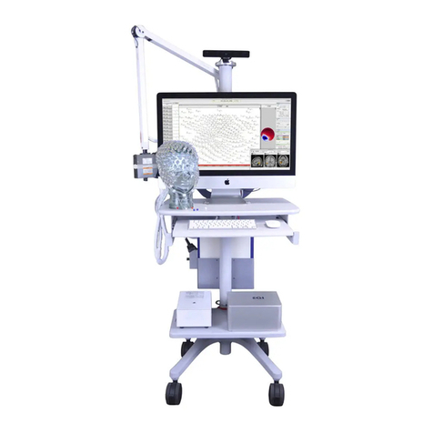
Figure P-1. Core components of a typical EEG-only GES system

10 GES 400 Series Clinical User Manual | 8100399-53 •2015-07-22
About This Manual
This manual provides concise information for using the GES system
to display and record EEG data. It assumes a working proficiency with
EEG and computer systems.
Note: The term patient is used to refer to subjects, participants, or patients.
An EGI support or authorized engineer will install and configure your EGI
system, including all connections required for its operation. At the time of initial
installation, the EGI support or authorized engineer will also train relevant staff
in its operation. At any time you have additional questions or wish retraining,
contact EGI Technical Support (Table P-3).
Typographic Conventions
•Italics are used for definitions or newly introduced terms.
•Boldface italics are used for important concepts or special
emphasis.
•Boldface is used for command paths (for example, File > Open).
Warnings, Cautions, and Notes
The following are used to convey important information:
WARNING: Warnings provide important information that, if
unheeded, could result in serious physical injury, death, or
equipment damage.
CAUTION: Cautions provide important information that, if
unheeded, could hinder the use of a product, feature, or
procedure, or result in physical injury or equipment failure.
Note: Notes provide clarifying information about a product, feature, or
procedure.

GES 400 Series Clinical User Manual | 8100399-53 •2015-07-22 11
Support, Repairs, and Documentation
If you have a question, please:
•For urgent issues during acquisition, contact EGI immediately.
•For nonurgent issues, do the following before contacting EGI:
–Isolate the problem. Try to repeat and define the
problem.
–Document the problem. Carefully record the
sequential details of the problem.
–Report the defined problem. Contact EGI.
Table P-3. EGI contact information
EGI Technical Support web page www.egi.com/support
Telephone +1.541.687.7962
Fax +1.541.687.7963
Address Electrical Geodesics, Inc. (EGI)
500 E 4th Avenue, Suite 200
Eugene, OR 97401
USA

12 GES 400 Series Clinical User Manual | 8100399-53 •2015-07-22

GES 400 Series Clinical User Manual | 8100399-53 •2015-07-22 13
1. Safety and Use
Conditions
WARNING: Never bring GES 400 components into the MR
environment.
Do not operate your GES system until you are fully trained and
understand all warnings, cautions, and conditions for use provided
in EGI’s manuals for the components of your GES system. If you have
any questions, contact EGI Technical Support (Table P-3).
WARNING: All EGI system components must be installed and
configured by an EGI support or authorized engineer. Deviating
from the supported configuration or running the system with
non-EGI-approved components attached can cause hazards or
unexpected performance.
Note that the information in this manual is subject to change, without notice. The
manufacturer declines responsibility for the safety, reliability, and performance of
EGI system components if not used in compliance with EGI documentation.
1.1 Intended Use
The Geodesic EEG System™ 400 Series (GES 400) is intended to
measure and record the electrical activity of the patient’s brain.
It can be used on adults, children, and infants.
Rx only.

14 GES 400 Series Clinical User Manual | 8100399-53 •2015-07-22
1.2 Features
•ADAPT™ technology for on-board computing and
remote updates
•Fiber optic signal input and output for optimal
digital bandwidth and safety isolation, including:
•Ethernet data and control with Net Station
•32 bipolar channel inputs, including Sp02, with
two Physio16 PNS devices
•Vertex referenced inputs
•4 kV patient isolation to mains ground and
1.5 kV isolation mains to mains ground
•Choice of sampling rates (see Table P-1)
•Full range of channel counts (32 to 256)
1.3 Regulatory Compliance
1.3.1 European Union (EU) Authorized Representative
Contact
Gerhard Frömel
Phone 011 49 6442 962073
Fax 011 49 6442 962074
Email [email protected]
Mailing Address
MPS
Medical Product Service GmbH
Borngasse 20
35619 Braunfels
Germany

GES 400 Series Clinical User Manual | 8100399-53 •2015-07-22 15
1.4 Conditions for Use
1.4.1 Environmental Conditions for Transport
and Storage
Table 1-1. Environmental conditions for the transport and storage of GES components
Shipping temperature 0˚ to 47˚C (32˚ to 116˚F)
Storage temperature -10˚ to 50˚C (14˚ to 122˚F)
Shipping humidity 5% to 95% noncondensing
Shipping altitude 11,500 m (37,700 ft) maximum
1.4.2 Environmental Conditions for Use
For EMC declarations, see Appendix A.
Table 1-2. Environmental conditions for the use of GES components
Operating temperature 10˚ to 35˚C (50˚ to 95˚F)
Relative operating humidity 5% to 95% noncondensing
Operating altitude 3,000 m (9,842 ft) maximum
1.4.3 Site Requirements for Location and Use
Table 1-3. Site requirements for the location and use of GES components
Location For indoor use only
Surface Area 102 x 150 cm (40 x 59 in.)
Ventilation Clearance 7.62 cm (3 in.)

16 GES 400 Series Clinical User Manual | 8100399-53 •2015-07-22
1.4.4 System Power
Table 1-4. Maximum power values for GES components
Device Rated Power Dissipation (watts)
NA 400 series amplifier 30
Mac Pro desktop computer 1,150
Mac 27-inch display 250
Dell computer 500
Dell 17-inch display 200
1.4.5 System Contraindications
No contraindications for the use of GES systems are known to exist.
1.4.6 Certifications and Classifications
For all current EGI regulatory certifications, including CE declarations, go to
www.egi.com or contact EGI Technical Support (Table P-3).
This medical equipment is certified to the following:
•CAN/CSA C22.2 No 601.1-M90 (Safety of Medical Electrical
Equipment, Part I: General Requirements for Safety)
•CSA 601.1 Supplement 1:1994 (Requirements for Safety)
•CSA 601.1 Amendment 2:1998
•CAN/CSA C22.2 No 60601-2-26:04 (Particular Requirements
for the Safety of Electroencephalograph)
•UL Standard No 60601-1 (1st Edition) (Safety of Medical
Electrical Equipment, Part I: General Requirements for Safety)

GES 400 Series Clinical User Manual | 8100399-53 •2015-07-22 17
•IEC 60601-2-26:2002 (Particular Requirements for the
Safety of Electroencephalograph)
•The GES 400 series systems carry the European CE mark
This medical equipment is classified as follows:
•Applied part: Type BF
•System: MDD Class IIa Equipment, Electrical Class I Equipment
•Articulated arms for the GES: Electrical Class I Equipment
1.4.7 Ratings
Table 1-5. Input ratings for GES components
Part Input Rating
GES External Power Supply 100-240 VAC, 50/60 Hz, 1.0 A
NA 400 series amplifier (from ext pwr sup) 12 VDC, 1.5 A
1.4.8 Interference
It is your responsibility to ensure that your GES system and its
components are safe and operate properly before using them.
All GES components have been tested and found to comply with
the electromagnetic compliance limits for the Medical Device
Directive 93/42/EEC (EN 60601-1-2:2007 Class A and JIS T 0601-1-
2:2002). See Appendix A.
These limits are designed to provide reasonable protection against
harmful interference in a typical medical installation. The
equipment generates radio-frequency energy and, if not installed
and used in accordance with the instructions, may cause
interference to other devices in the vicinity. If this equipment does
interfere with other devices, which can be determined by turning
the equipment off and on, try to correct the interference by one or
more of the following measures:

18 GES 400 Series Clinical User Manual | 8100399-53 •2015-07-22
•Reorient or relocate the receiving device.
•Increase the separation between the equipment.
•Connect the equipment to an outlet on a different circuit
than the one used by the other devices.
•Consult EGI Technical Support (Table P-3).
1.4.9 Symbols
The following symbols are used on GES components and in this
manual.
Table 1-6. Symbols used on GES components and in this manual
Symbol Description Symbol Description
MR unsafe Rx only Prescription medical
device
Imminent hazard
European conformity
Potential hazard
Canadian Standards
Association approval
Electrical hazard
Manufacturer
Type BF applied part
(body protected,
patient isolation)
EU authorized
representative
Interference hazard
Temperature limit
10˚C to 35˚C
(50˚F to 95˚F)
Functional earth
terminal
Humidity limits

GES 400 Series Clinical User Manual | 8100399-53 •2015-07-22 19
Symbol Description Symbol Description
Read product
documentation
(EGI and third-party mfr)
No unauthorized
servicing
Keep dry
Do not use in gas
environment
Always adhere to
IEC 60601-1-1 and
60601-1-2
Do not dispose with
other waste (comply
with local regulations)
Signal input Digital inputs
Linked Part number
Active Serial number
Locked
Power input
Ethernet Powered
Clock sync
1.5 Safety Warnings
1.5.1 General Safety Warnings
WARNING:
•Always connect all GES components to the isolation transformer.
Never connect components directly to mains electricity supply,
which may result in physical injury or equipment damage.
•Never deviate from supported configurations and never connect
non-EGI components to the isolation transformer or to other EGI
components. All EGI components must be installed and

20 GES 400 Series Clinical User Manual | 8100399-53 •2015-07-22
configured by an EGI support or authorized engineer. Deviating
from the supported configurations or running the system with
non-EGI components attached may result in unexpected hazards
or performance due to additional loading or leakage.
•Use only approved equipment. Do not connect the GES to
unauthorized equipment, as physical injury or equipment damage
may result. The user is responsible for ensuring that a reconfigured
GES meets all applicable local and national regulations for safety
and performance. See IEC 60601-1.
•Only connect GES components to a mains electricity supply
with protective earth to avoid the risk of electrical shock or
electrocution.
•Do not obstruct access to any GES component, including the
isolation transformer, such that it is difficult to access, difficult
to operate, or results in entanglements. The mains disconnect
(the isolation transformer’s mains disconnect switch) must
remain accessible.
•Certify all accessory equipment according to the relevant IEC
standards. Accessory equipment connected to the digital or
clock sync ports of the amplifier must be certified according to
the respective IEC standards (e.g., IEC 60950 for data processing
equipment and IEC 60601-1 for medical equipment).
Furthermore, all configurations shall comply with the system
standard IEC 60601-1-1. Any person who connects additional
equipment to the signal input port or signal output port
configures a medical system, and is therefore responsible for
ensuring that the system complies with the requirements of the
system standard IEC 60601-1-1. If in doubt, consult EGI Technical
Support (Table P-3).
•Ensure that the environment is safe. The room where GES
components are used must comply with all applicable local and
national safety requirements.
•Position the patient and operate the GES only as described in
this manual.
•Do not use in flammable gas environments.
•Do not use in oxygen rich environments.
This manual suits for next models
3
Table of contents
Other EGi Medical Equipment manuals