EGO POWER+ PTX5100 User manual

TELESCOPIC POLE SERIES
OPERATOR'S MANUAL
HEDGE TRIMMER ATTACHMENT
MODEL NUMBER PTX5100
WARNING: To reduce the risk of injury, the user must read and understand the
Operator’s Manual before using this product. Save these instructions for future reference.
MNL_EGO_PTX5100_AV01.01_210329
FOR USE ONLY WITH THE 56V LITHIUM-ION
TELESCOPIC POWER POLE PPX1000

-178°
A
5. Blade
Front Bushing
Rear Bushing
1. Rear Bushing 2. Front Bushing
3. Motor Housing
4. Blade Sheath
B C 42°
20°
-23°
-45° -68°
0°

I
H
D E
GF
J
-90° 90°
Nut
Bush
Bush
Plain
Washer Plain Washer
Long Bolt
Short Bolt
Nut
Nut
Tip Protector
K

L2
L1
M
O
N
Screw 1# (short screws)
Short Screw
Short Screw
Motor Cover
Motor
Washer
Gear Case
Planet Gears
Bottom Cover
Support Plate 3#
Screw 2# (long screw)
Blade Assembly
Oiling Hole Screw
Eccentric Block
Support Plate 2#
Support Plate 1#
Bushing
Link Lever

56-VOLT LITHIUM-ION HEDGE TRIMMER ATTACHMENT — PTX5100 5
EN
READ ALL INSTRUCTIONS!
READ OPERATOR’S MANUAL
Residual risk! People with electronic devices, such
as pacemakers, should consult their physician(s) before
using this product. Operation of electrical equipment
in close proximity to a heart pacemaker could cause
interference or failure of the pacemaker.
WARNING: To ensure safety and reliability, all
repairs and replacements should be performed by a
qualified service technician.
SAFETY SYMBOLS
The purpose of safety symbols is to attract your attention
to possible dangers. The safety symbols and the
explanations with them deserve your careful attention
and understanding. The symbol warnings do not, by
themselves, eliminate any danger. The instructions and
warnings they give are no substitutes for proper accident
prevention measures.
WARNING: Be sure to read and understand all
safety instructions in this Operator’s Manual, including all
safety alert symbols such as “DANGER,” “WARNING,”
and “CAUTION” before using this tool. Failure to follow all
instructions listed below may result in electric shock, fire,
and/or serious personal injury.
SYMBOL MEANING
SAFETY ALERT SYMBOL: Indicates DANGER,
WARNING, OR CAUTION. May be used in conjunction with
other symbols or pictographs.
WARNING: The operation of any power
tools can result in foreign objects being
thrown into your eyes, which can result in
severe eye damage. Before beginning power
tool operation, always wear safety goggles or
safety glasses with side shields and a full
face shield when needed. We recommend a
Wide Vision Safety Mask for use over
eyeglasses or standard safety glasses with
side shields.
SAFETY INSTRUCTIONS
This page depicts and describes safety symbols that may
appear on this product. Read, understand, and follow
all instructions on the machine before attempting to
assemble and operate it.
Safety Alert Indicates a potential
personal injury hazard.
Read
Operator’s
Manual
To reduce the risk of
injury, user must read the
operator’s manual.
Keep
sufficient
distance
away from
electrical
power lines
To prevent electrocution,
do not operate within 15m
of overhead electrical lines.
Contact with or use near
power lines may cause
serious injury or electric
shock resulting in death.
XX
Noise
Guaranteed sound power
level. Noise emission to the
environment according to
the European community’s
Directive.
XX
CE
This product is in
accordance with applicable
EC directives.
XX
WEEE
Waste electrical products
should not be disposed of
with household waste. Take
to an authorized recycler.
Keep
hands and
feet away
from the
cutting
tool
Never attempt to operate
your power tool with one
hand. Loss of control of
the power tool resulting in
serious or fatal injury may
result. To reduce the risk
of cut injuries, keep hands
and feet away from the
cutting tool. Never attach
a moving cutting tool with
your hand or any other
part of your body.
Wear eye
and head
protection
Always wear eye and head
protection when operating
this product.
IPX5 IP Symbol Protection against ingress
of water degree 5
V Volt Voltage
mm Millimeter Length or size
Original instructions

56-VOLT LITHIUM-ION HEDGE TRIMMER ATTACHMENT — PTX51006
EN
cm Centimeter Length or size
kg Kilogram Weight
Direct
Current
Type or a characteristic of
current
HEDGE TRIMMER SAFETY WARNINGS
◾Keep all parts of the body away from the cutter
blade. Do not remove cut material or hold material
to be cut when blades are moving. Make sure
the switch is off when clearing jammed material.
A moment of inattention while operating the hedge
trimmer may result in serious personal injury.
◾Carry the hedge trimmer by the handle with the
cutter blade stopped. When transporting or storing
the hedge trimmer always fit the cutting device cover.
Proper handling of the hedge trimmer will reduce
possible personal injury from the cutter blades.
◾When transporting or storing the hedge trimmer,
always fit the blade cover. Proper handling of the
hedge trimmer will decrease the risk of personal injury
from the blades.
◾When clearing jammed material or servicing the
unit, make sure all power switches are off and
the battery pack is removed or disconnected.
Unexpected actuation of the hedge trimmer while
clearing jammed material or servicing may result in
serious personal injury.
◾When clearing jammed material or servicing the
unit, make sure all power switches are off and the
lock-off is in the locked position. Unexpected actuation
of the hedge trimmer while clearing jammed material or
servicing may result in serious personal injury.
◾Hold the hedge trimmer by insulated gripping
surfaces only, because the blade may contact
hidden wiring. Blades contacting a “live” wire may
make exposed metal parts of the hedge trimmer “live”
and could give the operator an electric shock.
◾Keep all power cords and cables away from cutting
area. Power cords or cables may be hidden in hedges
or bushes and can be accidentally cut by the blade.
◾Do not use the hedge trimmer in bad weather
conditions, especially when there is a risk of lightning.
This decreases the risk of being struck by lightning.
ADDITIONAL SAFETY INSTRUCTIONS FOR
EXTENDED-REACH HEDGE TRIMMERS
◾To reduce the risk of electrocution, never use the
extended-reach hedge trimmer near any electrical
power lines. Contact with or use near power lines
may cause serious injury or electric shock resulting
in death.
◾Always use two hands when operating the
extended-reach hedge trimmer. Hold the extended-
reach hedge trimmer with both hands to avoid loss of
control.
◾Always use head protection when operating the
extended-reach hedge trimmer overhead. Falling
debris can result in serious personal injury.
◾Check the hedge for foreign objects before
operating, e.g. wire fences and hidden wiring.
◾Hold the power tool by insulated gripping surfaces only.
◾The hedge trimmer is intended to be used by the
operator at ground level and not on ladders or any
other unstable support
◾Use only with the battery packs and chargers listed in
as below:
BATTERY PACK CHARGER
BA1400, BA2800, BA4200,
BA1400T, BA2800T, BA4200T,
BA5600T
CH2100E, CH5500E
SAVE THESE INSTRUCTIONS
NOTE: SEE YOUR TELESOCPIC POWER POLE
OPERATOR’S MANUAL FOR ADDITIONAL SPECIFIC
SAFETY RULES.
SPECIFICATIONS
Blade Length 510 mm
Cutting Capacity 26 mm
Recommended Operating
Temperature -10°C ~ 40°C
Recommended Storage
Temperature -20°C ~ 70°C
Weight 2.67 kg
PACKING LIST
PART NAME QUANTITY
Hedge Trimmer Attachment 1
Blade Sheath 1
Operator’s Manual 1
DESCRIPTION
KNOW YOUR HEDGE TRIMMER ATTACHMENT (Fig. A)
1. Rear Bushing
2. Front Bushing
3. Motor Housing

56-VOLT LITHIUM-ION HEDGE TRIMMER ATTACHMENT — PTX5100 7
EN
4. Blade Sheath
5. Blade
ASSEMBLY
WARNING: If any parts are damaged or missing,
do not operate this product until the parts are replaced.
Use of this product with damaged or missing parts could
result in serious personal injury.
WARNING: Always remove the battery pack from
the product when you are assembling parts, making
adjustments, cleaning, or when the product is not in use.
CUTTING HEAD ANGLE ADJUSTMENT
When the hedge trimmer attachment is taken out from the
package, it has been folded in its storage position (Fig. B).
The articulation angle and radial rotation of cutting head
can be adjusted independently. Adjust the cutting head to
a suitable working position before operation.
Articulation Angle Adjustment
There are six working positions. The angle of the cutting
blade can be adjusted from -68°to 42°(Fig. C).
1. Pull back the front bushing, and then firmly hold the
motor cover to rotate the cutting angle to the desired
position.
2. Once the desired angle is reached, push forward the
bushing to lock the position of cutting head.
Radial Rotation Adjustment
There are two vertical cutting positions (Fig. D). It can be
adjusted to the left or right 90°.
1. Pull back the rear bushing, and then firmly hold
the motor cover to rotate the blade to the desired
position.
2. Once the desired angle is reached, push forward the
bushing to lock the position of cutting head.
WARNING: To reduce the risk of injury, remove
the battery before making adjustments and make
adjustments only when the blades are at a standstill.
Never touch the blades while making adjustments.
WARNING: The casting alloy gear case is hot. Never
touch the casting alloy gear case surface without wearing
a PPE gloves.
CONNECTING/REMOVING THE HEDGE TRIMMER
ATTACHMENT TO THE TELESCOPIC POWER POLE (FIG. E)
This hedge trimmer attachment is designed for use with
EGO telescopic power pole PPX1000.
See “INSTALLING AN ATTACHMENT TO THE
TELESCOPIC POWER POLE” section in the telescopic
power pole PPX1000 operator’s manual for connecting the
hedge trimmer to the power pole.
See “REMOVING THE ATTACHMENT FROM THE
TELESCOPIC POWER POLE” section in the telescopic
power pole PPX1000 operator’s manual to remove the
hedge trimmer from the power pole.
MOUNTING THE TIP PROTECTOR (Optional)
1. Use a hex wrench (not included) to remove the short
bolt, plain washer, bush and nut at the end of the
cutting blade Save the plain washer, bush and nut for
reassembly (Fig. F).
2. Align the tip protector with the bulge on the cutting
blade and mount it into place. Secure it with the new
long bolt and nut as well as the saved washer, bush
and nut (Fig. G).
OPERATION
DANGER: Never cut near power lines, electric
cords, or other electric sources. If the cutting blades
jam on any electrical cord or line, DO NOT TOUCH THE
BLADE OR THE ALUMINUM POLE! THEY CAN BECOME
ELECTRICALLY LIVE AND MAY BE VERY DANGEROUS.
Continue to hold the hedge trimmer attachment by the
insulated handle or lay it down and away from you in a safe
manner. Disconnect the electrical service to the damaged
line or cord before attempting to free the blade from the
line or cord. Contact with the blade, other conductive parts
of the hedge trimmer attachment, or live electric cords or
lines will result in death by electrocution or serious injury.
WARNING: Do not allow familiarity with this product
to make you careless. Remember that a careless fraction
of a second is sufficient to inflict serious injury.
WARNING: Always wear eye protection. Failure to do
so could result in objects being thrown into your eyes and
other possible serious injuries.
WARNING: Do not use any attachments or
accessories not recommended by the manufacturer
by EGOTM. The use of attachments or accessories not
recommended can result in serious personal injury.
APPLICATIONS
You may use this product for trimming the hedges,
shrubs, scrub, bushes and similar material with a branch
diameter of less than Ø26 mm.

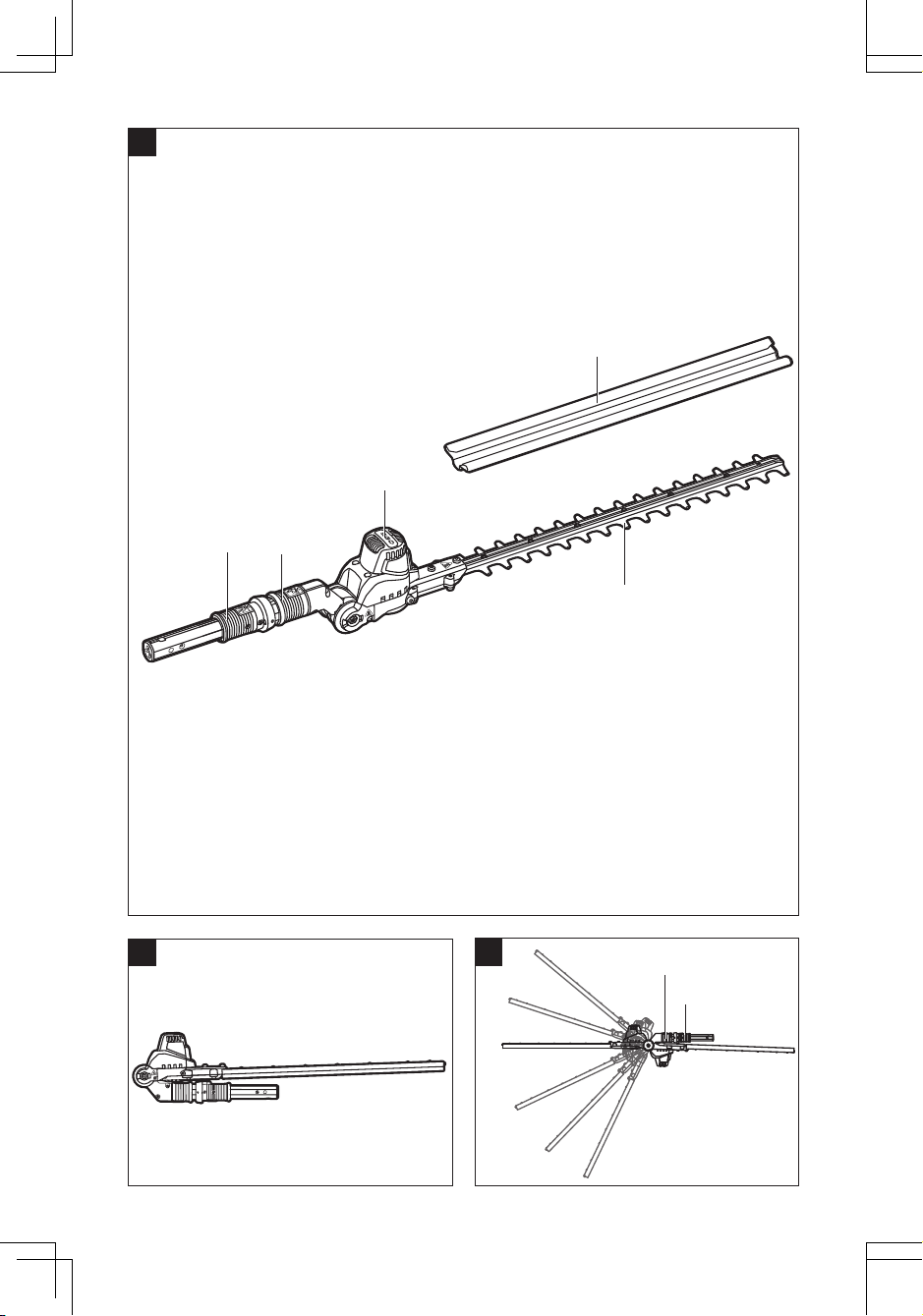
56-VOLT LITHIUM-ION HEDGE TRIMMER ATTACHMENT — PTX51008
EN
USING THE HEDGE TRIMMER WITH TELESCOPIC
POWER POLE
WARNING: Dress properly to reduce the risk of
injury when operating this tool. Do not wear loose clothing
or jewelry. Wear eye and ear/hearing protection. Wear
heavy, long pants, boots, and gloves. Do not wear short
pants or sandals or go barefoot.
PREPARATION FOR CUTTING:
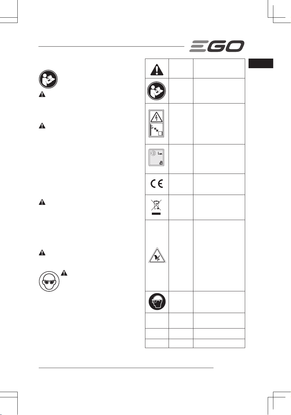
1. Adjust the cutting head to the desired working
position.
2. Remove the blade sheath from the cutting blade.
3. For safe and better operation, put on the shoulder
strap across the shoulder. Adjust the shoulder strap
into a comfortable operating position. Following
the instructions in the section “MOUNTING THE
SHOULDER STRAP” in PPX1000 operator’s manual
to attach the shoulder strap onto the power pole.
WARNING: The shoulder strap is also a quick
release mechanism in hazardous situation. When an
emergency occurs, take it off your shoulder immediately,
no matter what way the strap is in.
WARNING: Always use two hands when operating
the extended-reach hedge trimmer. Hold the extended-
reach hedge trimmer with both hands to avoid loss
of control. Following the instructions in the section
“HOLDING THE TELESCOPIC POWER POLE” in PPX1000
operator’s manual
WORKING TECHNIQUES
◾Horizontal Cutting (with cutting head at an angle)
Cut close to the ground from a standing position, e.g.
for trimming low shrubs. Swing the cutting head right
and left as you move along the hedge-use both sides
of the blades and do not rest the cutter blade on the
ground (Fig. H).
◾Horizontal Cutting (with straight cutting head)
Hold the cutting head at an angle of 0°as you slowly
swing the hedge trimmer horizontally. Swing the
cutting head in an arc towards the outsides of the
hedge so that the cuttings are swept to the ground
(Fig. I).
Recommendation: Cut hedges that are no more
than chest height in this working position.
◾Vertical Cutting (cutting head at an angle)
Cutting without standing directly next to the hedge, e.g.
flowerbed between operator and hedge.
In this cutting position, for your better control of the
hedge trimmer, it is recommended that connect the
hedge trimmer with the cutting head at the side cutting
position.
Swing the cutting head up and down in an arc as you
move along the hedge – use both sides of the cutting
blade (Fig. J).
◾Vertical Cutting (with straight cutting head)
Extra long reach without the need for other aids. Swing
the cutting head up and down in an arc as you move
along the hedge – use both sides of the cutting blade
(Fig. k).
◾Overhead Cutting (with cutting head at an angle)
Hold the hedge trimmer vertically and swing it in an
arc to make maximum use of its reach (Fig. L1&L2).
For extreme high hedge, the extension pole is suitable
for aids in trimming.
WARNING: Any working position above head height
is tiring. To minimize the risk of accidents, work in such
positions for short periods only. Set angle of adjustable
cutting head to maximum so that the tool can be held in a
lower, less tiring position (with shoulder strap) while still
providing adequate reach.
TO START/STOP THE TOOL
See “STARTING/STOPPING THE TELESCOPIC POWER
POLE” section in the power pole PPX1000 operator’s
manual.
MAINTENANCE
WARNING: When servicing, use only identical
replacement parts. Inspect and maintain the machine
regularly. To ensure safety and reliability, all repairs should
be performed by a qualified service technician.
WARNING: Before inspecting, cleaning or servicing
the unit, stop the motor, wait for all moving parts to stop,
and remove the battery pack. Failure to follow these
instructions can result in serious personal injury or
property damage.
NOTICE: Before each use, inspect the entire product
for damaged, missing, or loose parts such as screws,
nuts, bolts, caps, etc. Tighten securely all fasteners and
caps and do not operate this product until all missing or
damaged parts are replaced. Please contact customer
service or a qualified service technician.
GENERAL MAINTENANCE
Avoid using solvents when cleaning plastic parts. Most
plastics are susceptible to damage from various types of
commercial solvents and may be damaged by their use.
Use clean cloths to remove dirt, dust, oil, grease, etc.

56-VOLT LITHIUM-ION HEDGE TRIMMER ATTACHMENT — PTX5100 9
EN
CLEANING THE HEDGE TRIMMER ATTACHMENT
1. Stop the motor and remove the battery pack.
2. Clean dirt and debris from the hedge trimmer
attachment using a damp cloth with a mild detergent.
NOTICE: Do not use any strong detergents on the plastic
housing or the handle. They can be damaged by certain
aromatic oils such as pine and lemon.
STORING THE HEDGE TRIMMER ATTACHMENT
1. Stop the motor and remove the battery pack from the
telescopic power pole.
2. Remove the hedge trimmer attachment from the
telescopic power pole.
3. Clean all foreign material from the hedge trimmer
attachment.
4. Store it in a place that is inaccessible to children.
5. Keep away from corrosive agents such as garden
chemicals and deicing salts.
REPLACING THE BLADE
WARNING: Always wear gloves when handling the
blade; these components are very sharp and may contain
burrs.
1. Switch off the tool and remove the battery pack.
2. Adjust the blade to the horizontal position, ensuring
that the blade assembly is in line with the hedge
trimmer shaft for easy mounting (Fig. M).
3. Use a hex wrench (not included) to loosen the 6
screws 1# (short screws) in the bottom cover and
remove them.
4. Continue loosening the 2 screws 2# (long screws)
to remove the support plate 1# & 2#, as well as the
2 bushings. The 2 bushings are separately located
inside the two rounded rectangle slots in the blade
assembly.
5. Remove the support plate 3#.
6. Carefully remove the link lever from the blade.
7. Remove the blade assembly from the tool and ensure
that the eccentric block assembly position remains
unchanged.
8. Align the inward bulge on the new blade assembly
with the hole inside the link lever to install the new
blade assembly into place.
9. Insert the two bushings into the two rounded
rectangle separately.
10. Mount the support plate 1# and then mount the
support plate 2#.
11. Keep the inside holes in the blade, the bushings, and
the holes in the support plates in line with the screw
holes in the gear case. Install the 2 long screws into
the aligned holes and tighten them securely.
12. Slightly move the upper blade back and forth to
check whether the blade can move freely. If not,
reassemble the blades until the upper blade can
move freely.
13. Install the link lever.
14. Align the hole of support plate 3 #with the bulge on
the eccentric block to install the support plate into
place, ensuring that the plate is exactly located in the
center, parallel to both edges.
15. Mount the bottom cover onto the gear case and
secure it with 6 short screws.
LUBRICATING THE BLADE (Fig. N)
For best operation and longer blade life, lubricate the hedge
trimmer blade with anti-rusting oil after each use. DO NOT
FULLY FILL OIL HOLE WITH THE OIL.
1. Remove the oiling hole screw on the gear case by a
hex wrench (not included).
2. Inject 5g grease through the greasing hole to the
gearcase.
3. Tighten the screw once finished.
LUBRICATING THE DRIVE GEAR
For best operation and longer lifetime, lubricate the hedge
trimmer attachment drive gear with a special grease every
100 hours operation.
The grease should meet the following requirements:
◾NLGI Grade Penetration: NLGI-2;
◾Thickener Type: Polyurea;
◾Recommended Operating Temperature Range: -40°C
to 180°C;
◾Other than above, the grease should also be shear
stable with exceptional pressure characteristics and
excellent anti-wear property, and perfect oxidation
stability.
Follow the steps below to fill with the grease:
1. Switch off the tool and remove the battery pack.
2. Use a hex wrench (not included) to loosen and
remove 3 short screws on the motor cover and then
detach the motor cover (Fig. O).
3. Loosen the 3 short screws on the motor and then
detach the motor and the washer.

56-VOLT LITHIUM-ION HEDGE TRIMMER ATTACHMENT — PTX510010
EN
4. Use a grease gun (not included) to inject 5g grease at
the center of the 3 upper planet gears into the gear
case.
NOTE: Ensure the position of other parts near the gear
case remains unchanged during injection.
5. Reassemble the washer and the motor by tightening
the 3 short screws.
6. Reassemble the motor cover by tightening the 3
short screws.
7. Start the tool to check whether it can work normally.
If it does not, reassemble by following above steps.
NOTE: After removing the motor cover, clean up the
sawdust around the motor.
Protecting the environment
Do not dispose of electrical appliances as
unsorted municipal waste, use separate
collection facilities.
Contact your local government for
information regarding the collection
systems available.
If electrical appliances are disposed of in
landfills or dumps, hazardous substances
can leak into the groundwater and get
into the food chain, damaging your health
and well-being.

56-VOLT LITHIUM-ION HEDGE TRIMMER ATTACHMENT — PTX5100 11
EN
TROUBLESHOOTING
PROBLEM CAUSE SOLUTION
Hedge trimmer doesn’t
work.
◾No electrical contact between the trimmer
and battery.
◾Remove battery, check contacts and
reattach the battery pack.
◾The battery pack is depleted. ◾Charge the battery pack.
◾The battery pack or tool is over-
temperature protection
◾Allow the battery pack or power pole
to cool until the temperature drops
below 67°C.
◾The blade is jammed. ◾Remove the battery pack from the
tool. Remove the obstruction carefully
and then reinsert the battery and
restart the tool.
Excessive vibration or
noise.
◾Dry or corroded blades. ◾Lubricate the blades.
◾Blades or blade support is bent. ◾Replace with a new blade or support
following the section“ REPLACING THE
BLADE” in this manual or contact EGO
service center for replacement.
◾Bent or damaged teeth. ◾Replace with a new blade following
the section“ REPLACING THE BLADE”in
this manual or contact EGO service
center for replacement.
◾Loose blade bolts. ◾Tighten the blade bolts. Using a hex
wrench (not included), turn the bolt
clockwise to tighten.

56-VOLT LITHIUM-ION HEDGE TRIMMER ATTACHMENT — PTX510012
EN
WARRANTY
EGO WARRANTY POLICY
2 year warranty on EGO outdoor power equipment and 1 year warranty on EGO Power+ System battery packs and
chargers.
Please contact EGO customer service on Australia 1300 000 EGO(1300 000 346),
New Zealand 0508 000 EGO (0508 000 346) any time you have questions or warranty claims.
LIMITED SERVICE WARRANTY
FOR TWO YEARS from the date of original retail purchase, this EGO product is warranted against defects in material or
workmanship. Defective product will receive free repair.
FOR ONE YEAR from the date of original retail purchase, the EGO Power+ System battery pack and charger are
warranted against defects in material or workmanship. Defective product will receive free repair.
This warranty does not cover the blade, which is a part that can wear out from normal use within the warranty period.
◾This warranty applies only to the original purchaser at retail and may not be transferred.
◾Warranty for commercial use is 1 year on all product, battery and chargers. The Commercial Series Product Warranty
for commercial users is 2 years for product, battery and charger.
◾This warranty is void if the product has been used for rental purpose.
◾This warranty does not cover the damage resulting from modification, alteration or unauthorised repair.
◾This warranty only covers defects arising under normal usage and does not cover any malfunction, failure or defect
resulting from misuse, abuse (including overloading of the product beyond capacity and exposure to water or rain),
accidents, neglect or lack of proper installation, and improper maintenance or storage.
◾This warranty does not cover normal deterioration of the exterior finish, including but not limited to scratches, dents,
paint chips, or to any corrosion or discoloring by heat, abrasive and chemical cleaners.
HOW TO OBTAIN SERVICE
For warranty service, please contact EGO customer service on Australia 1300 000 EGO(1300 000 346), New Zealand
0508 000 EGO (0508 000 346). When requesting warranty service, you must present the original dated sales receipt. An
authorised service center will be selected to repair the product according to the stated warranty terms.
ADDITIONAL LIMITATIONS
Chervon Australia Pty Ltd ABN 36 165 077 501(“Chervon”) warrants to the original domestic purchaser that this
product will be free from defects in materials and workmanship for 2 years from date of purchase, and any battery or
charger will be free from defects in materials and workmanship for 1 year from date of purchase. To make a claim,
return the faulty item together with proof of purchase directly to your closest service agent or to the place of purchase.
Any handling and transportation costs (and other expenses incurred in claiming this warranty) are not covered by this
warranty and will not be borne by Chervon. The replacement product or part or repaired product will be made available
for your collection at an address nominated by Chervon. Where a valid warranty claim is made, Chervon will replace
the defective product or repair the fault. Where the product is repaired, Chervon may use refurbished parts. This
warranty does not cover normal wear and tear, misuse or abuse. This warranty may also be further limited or voided
as specifically detailed in the product Manual. Chervon has no other liability under this warranty.The benefits to you
given by this warranty are in addition to other rights and remedies imposed by State and Federal legislation that cannot
be excluded. Our goods come with guarantees that cannot be excluded under the Australian Consumer Law. You are
entitled to a replacement or refund for a major failure and compensation for any other reasonably foreseeable loss or
damage. You are also entitled to have the goods repaired or replaced if the goods fail to be of acceptable quality and the
failure does not amount to a major failure.
Chervon Australia Pty Ltd, Unit Unit 14, 5 Kelletts Road, Rowville, VIC 3178.
Phone Number: Australia 1300 000 EGO(1300 000 346), New Zealand 0508 000 EGO (0508 000 346).
Other manuals for POWER+ PTX5100
2
Table of contents
Other EGO Trimmer manuals