manuals.online logo
Brands
  1. Home
  2. •
  3. Brands
  4. •
  5. Ekinex
  6. •
  7. Recording Equipment
  8. •
  9. Ekinex EK-EH2-TP User manual

Ekinex EK-EH2-TP User manual

1
6-fold KNX pushbutton
Product code: EK-EH2-TP-...
• Sending on the bus of values (temperature, etc.)
• Switching to forced functioning (lock)
• Measuring of room temperature through the integrated
sensor
• Di󰀨erent functions programmable for short pressure /
long pressure of a rocker
• Status feedback or orientation nightlight through 2-co-
lor programmable LEDs
Other characteristics
• Housing in plastic material
• Wall installation in ush mounting box
• Protection degree IP20 (according to EN 60529)
• Classication climatic 3K5 and mechanical 3M2 (accor-
ding to EN 50491-2)
• Pollution degree 2 (according to IEC 60664-1)
• Weight 50 g (70 g with mounting support)
• Dimensions 122 x 78 x 19 mm (WxHxD)
Technical data
• Power supply 30 Vdc from KNX bus line
• Current consumption < 15 mA
• Power from bus < 360 mW
Environmental conditions
• Operating temperature: - 5 ... + 45°C
• Storage temperature: - 25 ... + 55°C
• Transport temperature: - 25 ... + 70°C
• Relative humidity: 95% not condensing
Completion of the pushbutton
KNX device for switching and control single loads or
groups of loads. It has to be used in KNX installations for
control of homes and buildings.
Description
The ekinex® 6-fold pushbutton (max 12 functions) is a S-
mode KNX device for on/o󰀨 switching of loads, dimming
of lighting devices, controlling of motor drives or other pro-
grammable switching and control functions. It is equipped
with an integrated KNX bus communication module and
is designed for wall installation on ush mounting box.
Each channel can be freely programmed for 1 or 2 bus
functions and is provided with two LEDs congurable for
example as a status signal or orientation nightlight. The
pushbutton has to be completed with six rockers and a
frame that must be ordered separately. Pushing a rocker,
the device sends on the bus a telegram, which is received
and executed by one or more KNX actuators. The device
is powered by the KNX bus line with a SELV voltage 30
Vdc and does not require auxiliary power.
Versions
The pushbutton is available with two combinations of co-
lours for the LEDs (blue/green and red/white).
Datasheet STEKEH2TP_EN
Main functional characteristics
• On/o󰀨 switching of single loads or groups of loads
• Dimming of lighting devices
• Control of motor drives (for roller shutters, blinds, cur-
tains, etc.)
• Recalling and saving of scenes
For installation and operation an ekinex®pushbutton must
be completed with a separate order of:
• operation elements consisting of six square rockers;
• one rectangular frame of the ekinex® form or ank se-
ries.
Rockers and frames are available in plastic or metal ver-
sions. The metallic support, the xing screws (two pairs)
and the KNX terminal block for connection of the bus line
are supplied with the device.
Note. Rockers and frame for the completion of the
device must be ordered separately. For more infor-
mation on materials, colors and nishes available,
see also the ekinex®product catalog or browse
www.ekinex.com
i
TP1
S
Code LED colours Mounting
EK-EH2-TP blue / green with rectangular frame, form
or ank series
EK-EH2-TP-RW red / white
Device completed with EK-FOR-... (form) frame and EK-TQQ-... rockers
Device completed with EK-FLR-... (ank) frame and EK-TQQ-... rockers
RFLEKEH2TP
2
Rockers
Three-positions rockers with central neutral position have
to be mounted on the pushbutton. Pushing one side of
a rocker (for example the upper one), the pushbutton
sends on the bus a telegram for switching on, increasing
the brightness of luminaires or raising the blinds, while
pushing the other side (for example the lower one), it sen-
ds a telegram for switching o󰀨, reducing the brightness of
luminaires or lowering the blinds. Each channel is equip-
ped with LEDs which can be freely programmed as status
feedbacks of the loads and as orientation nightlight.
Switching, display and connection elements
The device is equipped with mechanisms for switching, 2
LEDs for each channel, a programming LED and a pro-
gramming pushbutton and a terminal block for connection
of the bus line.
Switching elements
• Pushbutton (3) for switching between the normal and
programming operating mode
• Mechanisms (4) for independent switching of single or
group of loads (to be completed with square rockers)
Customization of rockers
The rockers can be customized with symbols and texts,
for more information see the standard library on the eki-
nex® catalog or the website www.ekinex.com. On request
it is also possible a customization with symbols and texts
chosen by the customer.
Frame
The device is completed with a rectangular frame of the
form (EK-FOR-...) or ank (EK-FLR-...) series.
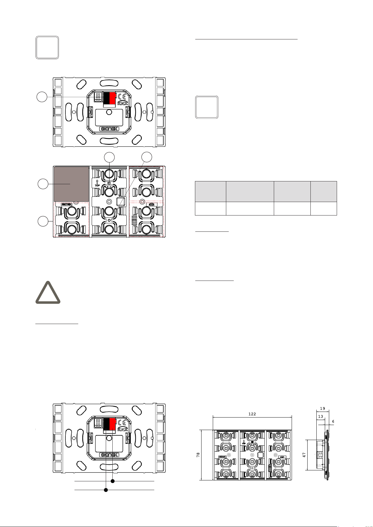
1) Rockers (to be ordered separately)
2) Screws to fasten the pushbutton on the metallic support
3) 6-fold pushbutton
4) Frame of the series form or ank (to be ordered separately)
5) Metallic support for mounting wall box
6) Screws for xing the support on the wall box
7) Flush-mounting box
Code * Material Package Modularity
[mm]
EK-TQQ-GAx plastic
4 pcs.
square 40 x 40
EK-TQQ-GBx metal
EK-TRO-GAx plastic 4 pcs. rec-
tangular 80 x 20
EK-TRO-GBx metal
(*) It has to be completed with the extension for the colour choosed (x)
Note. The application program allows to congure
the pushbutton with a combination of square and
rectangular rockers. For the allowed combinations
see the application manual or the application pro-
gram for ETS.
i
Code * Material Package Dimens.
[mm]
EK-FOR-GAx plastic
1 pcs. 126 x 86
EK-FOR-GBx metal
EK-FLR-GAx plastic
1 pcs. 135 x 80
EK-FLR-GBx metal
(*) It has to be completed with the extension for the colour (x)
Mounting
The device has degree of protection IP20, and is therefo-
re suitable for use in dry interior rooms. The installation of
the device requires the following steps:
a) x the metallic support (5) with the screws supplied
(6) on the wall box (7) provided with suitable xing holes;
b) snap a rectangular frame (4) of the form or ank series,
inserting it from the rear of the device (3);
c) enter the bus terminal, previously connected to the bus
cable in its slot on the rear side (see also: “Connection
of the KNX bus line”). At this point it is recommended to
carry out the commissioning of the device (see also “Con-
guration and commissioning”) or at least the download of
the physical address;
d) mounting the device (3) on the metallic support sup-
plied (5) with the screws (2). The correct mounting of the
device occurs when the bus terminal is located in the lo-
wer part; for mounting the device follow also the indication
TOP (arrow tip pointing up) on the rear side of the device.
e) snap the six rockers (1) on the device.
The 6-fold pushbutton can be mounted on a round or a
square (60 mm hole centres) or a rectangular (83,5 mm
hole centres) ush-mounting box. If necessary, the me-
tallic support for mounting on the wall box can also be
ordered separately using the code EK-SMR.
Mounting
not allowed
(xing
elements
aligned
horizontally)
ESEKEH2TP
234 5 7
6
1
Note. The screws supplied in the package are su-
itable for standard installations. For more specic
applications, where the screws have to be replaced,
only at-head screws must be used.
i
Mounting of rockers
For the mounting of the rockers on the dedicated seats,
the xing elements must be aligned vertically.
Note. The screws for the metal support must be
tightened with a max. torque of 1.0 Nm.
3
DQEKEH2TP
Display elements
• Red LED (2) for indication of the active operating mode
(on = programming, o󰀨 = normal operation)
• Freely programmable LEDs with lightguide e.g. for
feedback status and orientation nightlight
Connection of the KNX bus line
The connection of the KNX bus line is made with the ter-
minal block (black/red) included in delivery and inserted
into the slot of the housing.
Characteristics of the KNX terminal block
• spring clamping of conductors
• 4 seats for conductors for each polarity
• terminal suitable for KNX bus cable with single-wire
conductors and diameter between 0.6 and 0.8 mm
• recommended wire stripping approx. 5 mm
• color codication: red = + (positive) bus conductor,
black = – (negative) bus conductor
Conguration
For the conguration of the device parameters the corre-
sponding application program or the whole ekinex®pro-
duct database must be loaded in the ETS program. For
detailed information on conguration options, refer to the
application manual of the device available on the website
www.ekinex.com.
Commissioning
For commissioning the device the following activities are
required:
• make the electrical connections as described above;
• turn on the bus power supply;
• switch the device operation to the programming mode
by pressing the programming pushbutton located on
the rear side of the housing. In this mode of operation,
the programming LED is turned on;
• download into the device the physical address and the
conguration with the ETS®program.
At the end of the download the operation of the device
automatically returns to normal mode; in this mode the
programming LED is turned o󰀨. Now the bus device is
programmed and ready for use.
Dimensions [mm]
Conguration and commissioning
Conguration and commissioning of the device require
the use of the ETS®(Engineering Tool Software) program
V4 or later releases. These activities must be carried out
according to the design of the building automation system
done by a qualied planner.
Note. Programming pushbutton and LED are only
accessible from the front side of the device. It is bet-
ter addressing the device before the nal assem-
bly of rockers and frame. Once the addressing has
been performed, the device conguration can be la-
ter downloaded without pressing the programming
pushbutton.
i
Warning! In order to supply the KNX bus lines use
only KNX bus power supplies (e.g. ekinex EK-AB1-
TP or EK-AG1-TP). The use of other power supplies
can compromise the communication and damage
the devices connected to the bus.
!
Warning! The electrical connection of the device
can be carried out only by qualied personnel. The
incorrect installation may result in electric shock or
re. Before making the electrical connections, make
sure the power supply has been turned o.
!
Product
code
Application program
(## = release)
Communica-
tion objects
(max nr.)
Group
adresses
(max nr.)
EK-EH2-TP
APEKEH2TP##.knxprod
232 232
Note. The conguration and commissioning of KNX
devices require specialized skills. To acquire these
skills, you should attend the workshops at KNX cer-
tied training centers.
i
1) Connection terminal block for KNX bus line
2) Programming LED
3) Programming pushbutton
4) Rocker
5) Lightguide for LED
DCEKEH2TP
DCEKEH2TP
5
1
4
23
DCEKEH2TP
ELEKEH2TP
+
-
Bus
KNX
4
Documentation
This datasheet refers to the release A1.0 of the ekinex®
device EK-EH2-TP, and is available for download at www.
ekinex.com as a PDF (Portable Data Format) le.
Warnings
• Installation, electrical connection, conguration and
commissioning of the device can only be carried out by
qualied personnel in compliance with the applicable
technical standards and laws of the respective countri-
es
• Opening the housing of the device causes the imme-
diate end of the warranty period
• In case of tampering, the compliance with the essential
requirements of the applicable directives, for which the
device has been certied, is no longer guaranteed
• ekinex® KNX defective devices must be returned to the
manufacturer at the following address: EKINEX S.p.A.
Via Novara 37, I-28010 Vaprio d’Agogna (NO) Italy
File name Device release Updating
STEKEH2TP_EN.pdf A1.0 02/2021
Marks
• KNX
• CE: the device complies with the Low Voltage Directi-
ve (2006/95/EC) and the Electromagnetic Compatibility
Directive (2004/108/EC). Tests carried out according to
EN 50491-5-1:2010, EN 50491-5-2:2010
135 8
80
Rectangular frame of
the ank series
(EK-FLR-...)
Other information
• This datasheet is aimed at installers, system integra-
tors and planners
• For further information on the product, please contact
the ekinex®technical support at the e-mail address:
[email protected] or visit the website www.ekinex.
com
• Each ekinex®device has a unique serial number on
the label. The serial number can be used by installers
or system integrators for documentation purposes and
has to be added in each communication addressed to
the EKINEX technical support in case of malfunctioning
of the device
• KNX®and ETS® are registered trademarks of KNX As-
sociation cvba, Brussels
© EKINEX S.p.A. The company reserves the right to make changes to this
documentation without notice.
Disposal
At the end of its useful life the product
described in this datasheet is classied
as waste from electronic equipment in
accordance with the European Direc-
tive 2002/96/EC (WEEE), and cannot
be disposed together with the munici-
pal undi󰀨erentiated solid waste.
Warning! Incorrect disposal of this product may
cause serious damage to the environment and hu-
man health. Please be informed about the correct
disposal procedures for waste collecting and pro-
cessing provided by local authorities.
!
126
86
8
Rectangular frame of
the form series
(EK-FOR-...)
Maintenance
The device is maintenance-free. To clean use a dry cloth.
It must be avoided the use of solvents or other aggressive
substances.

This manual suits for next models

2

Other Ekinex Recording Equipment manuals

Ekinex KONNECT4 Instruction sheet

Ekinex

Ekinex KONNECT4 Instruction sheet

Ekinex EK-CG2-TP User manual

Ekinex

Ekinex EK-CG2-TP User manual

Ekinex KONNECT4 User manual

Ekinex

Ekinex KONNECT4 User manual

Ekinex EK-CF2-TP Instructions for use

Ekinex

Ekinex EK-CF2-TP Instructions for use

Ekinex EK-CG2-TP Instructions for use

Ekinex

Ekinex EK-CG2-TP Instructions for use

Ekinex EK-IE1-SEC-TP User manual

Ekinex

Ekinex EK-IE1-SEC-TP User manual

Popular Recording Equipment manuals by other brands

Pyle PS1000 user manual

Pyle

Pyle PS1000 user manual

Enabling Devices 5015 user guide

Enabling Devices

Enabling Devices 5015 user guide

Avolites Pearl Expert Titan Operator's manual

Avolites

Avolites Pearl Expert Titan Operator's manual

NavInc BT-VW-12P quick start guide

NavInc

NavInc BT-VW-12P quick start guide

Helmer i.C3 user guide

Helmer

Helmer i.C3 user guide

ETC Echo Contact Input installation guide

ETC

ETC Echo Contact Input installation guide

KAP TYT-TU-171115 instruction manual

KAP

KAP TYT-TU-171115 instruction manual

TC-Helicon SINGTHING user manual

TC-Helicon

TC-Helicon SINGTHING user manual

Behringer B-Control Fader BCF2000 quick start guide

Behringer

Behringer B-Control Fader BCF2000 quick start guide

Klementz POWERSIREN user manual

Klementz

Klementz POWERSIREN user manual

PRESONUS FIRESTUDIO MOBILE - SCHEMA Quick setup

PRESONUS

PRESONUS FIRESTUDIO MOBILE - SCHEMA Quick setup

Trilithic Visionary HD/SD Overlay System Hardware installation and configuration manual

Trilithic

Trilithic Visionary HD/SD Overlay System Hardware installation and configuration manual

MIDICRAFT PUSH user manual

MIDICRAFT

MIDICRAFT PUSH user manual

Axxess AXDIS-GM13 installation instructions

Axxess

Axxess AXDIS-GM13 installation instructions

Vivaldi DA8 user manual

Vivaldi

Vivaldi DA8 user manual

Digital Loggers F16 installation guide

Digital Loggers

Digital Loggers F16 installation guide

California AUDIO LABS CL-2500 SSP user guide

California AUDIO LABS

California AUDIO LABS CL-2500 SSP user guide

Minebea CC-Link CSD-709-73 instruction manual

Minebea

Minebea CC-Link CSD-709-73 instruction manual

manuals.online logo
manuals.online logoBrands
  • About & Mission
  • Contact us
  • Privacy Policy
  • Terms and Conditions

Copyright 2025 Manuals.Online. All Rights Reserved.