manuals.online logo
Brands
  1. Home
  2. •
  3. Brands
  4. •
  5. Ekinex
  6. •
  7. Recording Equipment
  8. •
  9. Ekinex KONNECT4 User manual

Ekinex KONNECT4 User manual

1
Konnect4 is a web-server designed to o󰀨er a suite
of connectivity and functional services to a Control4
supervision system, when used in combination with
ekinex KNX devices.
Technical Sheet STEKBR1TP_EN
particular operations in progress
• 1 RESET button housed under the front cover on the
back of the vertical card
Other features:
• Plastic housing
• Design for mounting on 35 mm prole rail (according
to EN 60715)
• Degree of protection IP20 with product installed (accor-
ding to EN 60529)
• Insulation class II (according to EN 60335-1
• Climatic classication 3K5 (indoor, dry) and mechanical
3M2 (according to EN50491-2)
• Device weight: 120 g
• 2 UM modular device (1 UM = 18 mm)
• Dimensions 36 x 90.5 x 62 mm (W x H x D)
Environmental conditions:
• Operating temperature: 0°C ... + 40°C
• Storage temperature: - 10 ... + 70°C
• Transport temperature: - 10 ... + 70°C
• Relative humidity: 95% non-condensing
Operating, signaling and connection elements
Konnect4 server is equipped with status LEDs, a RESET
button located under the front panel of the device, ter-
minals for power supply connection, KNX bus line and
Ethernet network. The server o󰀨ers also an USB and
RS485 port, prepared for future use (not available at the
present moment in the conguration process).
KONNECT4, advanced IP-KNX interface for
KNX and/or Control4 installations
Description
Konnect4 server is designed for installation on DIN prole
rail and occupies 2 modules. The 12-24 Vdc power supply
is external (power supply not included). The product with
hardware based on embedded operating system, has a
KNX TP node (twisted pair) and can therefore be con-
nected directly to the bus network of KNX devices. Con-
nectivity as an IP gateway for Control4 is via the Ethernet
port. The integrated web server built with HTML5 techno-
logy allows access to the conguration environment.
With KONNECT4 it is possible to:
• Send commands and receive information from KNX de-
vices in the CONTROL4 system
• Monitor the building energy consumption and control
loads accordingly with the overall absorption with a de-
dicated graphic driver for Composer
• Make a continuous diagnostic check on the KNX de-
vices and receive notications in case of malfunctions
• Dene command sequences (scenes) and execute
them with simple connections in Composer with 3rd
party drivers
• Perform logics congurable with a graphic editor and
executed in background
• Send notications to CONTROL4 in case of malfun-
ctions or congurable events on the bus
Main features
• 12-24 Vdc power supply (absorption 240 mA at 12 Vdc)
by means of a special plug-in terminal supplied. Power
supply not included
• KNX TP bus (twisted pair) via red-black terminal pro-
vided
• 1 Ethernet port via cat. 5 or higher cable and standard
RJ45 connector
• 1 RS485 port for future integrations
• 1 USB 2.0 port: for future integrations
• 2 frontal LEDs: POWER LED for signalling the pre-
sence of power supply; SERVICE LED for signalling
6
4
5
3
1
2
1. LED SERVICE
2. LED POWER
3. RESET push-button
4. Clamp for power-supply 12-24 Vdc
5. Clamp for KNX bus
6. RJ45 Ethernet plug
7. Clamp for RS485 network
8. 2.0 USB port
Signaling elements
• POWER LED: indicates the presence of 12-24 Vdc po-
wer supply at terminals
• SERVICE LED: Normally o󰀨, steady mode or ashing
during IP address recovery sequences or factory re-
congurations
Control elements
• RESET button: must be pressed to activate IP address
reset sequences or factory settings.
Codes: EK-BR1-TP
8
7
2
Note. The RESET button is not directly accessible on the front
panel of the product. To access the button, open the front pa-
nel of the Konnect4 server using a small slotted screwdriver and
exerting a slight leverage eect in one of the side slots. Locate
the RESET button on the back of the vertical board at the bottom
of the device towards the KNX terminals.
Warning! KONNECT4 is supposed to be connected to the same
LAN as the CONTROL4 controller(s); in case of dierent instal-
lations, please refer to the IT manager in order to ensure the
proper communication
Mounting
The device has degree of protection IP20, and is there-
fore suitable for use in dry interior rooms. The housing is
made for rail mounting according to EN 60715 in boards
or cabinets for electrical distribution. The installation is in
horizontal position, the correct position is when the KNX
bus terminal is located at the bottom and the terminals for
the outputs are located at the top.
For the installation of the device on the rail proceed as
follows:
• with the aid of a tool bring the locking device in the fully
lowered position (1);
• place the upper edge of the rear inner prole on the
upper edge of the rail (2);
• rotate the device towards the rail (3);
• push the locking device upward until it stops (4).
!
!
!
i
Before removing the device, be sure the inputs have been
disconnected and the bus terminal has been extracted
from its slot. Use a screwdriver to slide down the locking
device and remove the device from the rail.
i
Clamp characteristics
• Screw tightening of conductors
• Max. conductor cross-section 2.5 mm2
• Recommended conductor stripping approx. 6 mm
• Max. torque 0.5 Nm
bus KNX
Note. It is recommended that the installation of the device
always ensure the full accessibility of the front side to allow the
led visualization.
Power 12-24 Vdc
The connection to the power supply is made via the
screw terminals (1)+ and (2)- located on the removable
2-pin connector.
Warning! The electrical connection of the device may only be
carried out by qualied personnel.
Connection to the KNX bus network
The connection to the bus network is made via the KNX
terminal included in the scope of delivery and inserted
into the housing on the front of the device at the bottom.
KNX clamp characteristics
• Spring clamping of the conductors
• 4 conductor seats for each polarity
• Suitable for KNX bus cable with single conductors
between 0.6 and 0.8 mm diameter
• Recommended conductor stripping approx. 5 mm
• Colour coding: red = bus conductor + (positive), black =
bus conductor - (negative)
Warning! Only use KNX bus power supplies (e.g. ekinex
EK-AB1-TP or EK-AG1-TP) to supply the KNX bus lines. The
use of other power supply devices can impair communication
and damage the devices connected to the bus.
3
i
First access
When you open the browser at the default address, the
following login screen is displayed:
This specic functionality does not require any congu-
ration in KONNECT4, and can be easily reached with a
standard KNX communication driver o󰀨ered by Control4.
Conguration and commissioning
The conguration and commissioning of the Konnect4
server must be carried out by accessing the web server
integrated in the product. These activities must be carried
out in accordance with the design of the building automa-
tion system carried out by a qualied professional.
Network connection
The conguration and use of the Konnect4 server requi-
res a connection to the home or company network. The
default IP address of the delégo server is:
192.168.0.110
For the initial conguration of the server, as well as in
case of absence of a network during the installation pha-
se, it is necessary to proceed as follows:
• connect the server Konnect4 to your PC via a “cross
over” (or “crossover”) network cable
• access your PC’s network settings, as illustrated in
your operating system documentation
• Change the TCP/IP communication protocol settings
(version 4) for the LAN port of your PC, and set the
following parameters manually:
• IP address: 192.16 8.0.100
• Network mask: 255.255.255.0
• Default gateway: 192.168.0.1
• Save and wait for the new settings to take e󰀨ect.
If prompted, reboot the system.
After these operations, open an Internet browser and type
in the address bar:
http://192.168.0.110
Connection as IP gateway for Control4
KONNECT4 can be used as IP gateway for CONTROL4,
in order to make the COMPOSER PRO to communicate
with KNX devices.
User Password Description
admin admin
Automation system
administrator user.
He has the rights
to create users,
manage their rights
and congure the
supervision
user user
Basic user. It
has the rights to
view the system
status, navigate the
supervision pages
and perform basic
commands on the
automation system
For an optimal browsing experience, we recommend
using one of the following browsers:
• Google Chrome
• Apple Safari
Konnect4 server has the following preset users at the
factory:
Enter the credentials of the user “admin” and conrm to
access the main screen of the Konnect4 administration
environment.
Restore factory IP address
If necessary, you can restore the factory IP address of
the server Konnect4 using the RESET button available.
Follow the procedure below:
• open the front panel of the server Konnect4 using a
small slotted screwdriver, and exerting a slight leverage
e󰀨ect in one of the side slots
• locate the RESET button on the back of the vertical
card
• press the button for at least 10 seconds until the SER-
VICE LED on the front of the device starts ashing,
then release the button
• within the next 5 seconds, press and release the button
for 1 second; within a couple of seconds the front LED
will light up solidly for a couple of seconds
• when the LED goes out, the device can be reached at
the factory IP address (192.168.0.110)
If the LED goes out after long press (10 seconds) before
short press, repeat the whole procedure. This procedure
resets the IP address and retains all data relating to the
conguration previously carried out on the automation sy-
stem.
Restore factory conguration
If the conguration made makes it impossible to access
the server Konnect4 or its correct use, it is possible to
restore the factory conditions, resetting the IP address
4
and emptying the supervision project using the “RESET”
button available. In this case, compared to what was pre-
viously seen to restore the IP address, the procedure to
follow is the following:
• open the front panel of the server Konnect4 using a
small slotted screwdriver, and exerting a slight leverage
e󰀨ect in one of the side slots
• locate the RESET button on the back of the vertical
card
• press the RESET button for at least 10 seconds un-
til the SERVICE LED on the front of the device starts
ashing, then release the button.
• within the next 5 seconds, press and hold the button for
at least 10 seconds
• when the LED is solidly lit, release the button and wait
for it to go out.
• when the LED goes o󰀨, remove and restore the power
supply
• wait about one minute and log in to the server with the
factory IP address (192.168.0.110).
!
!
Disposal
File name Device
Release Update
STEKBR1TP_EN.pdf A1.0 06/2020
Warning! To avoid losing all the congurations made for the au-
tomation project during a factory reset operation, it is recommen-
ded to make periodic backups of the supervision project.
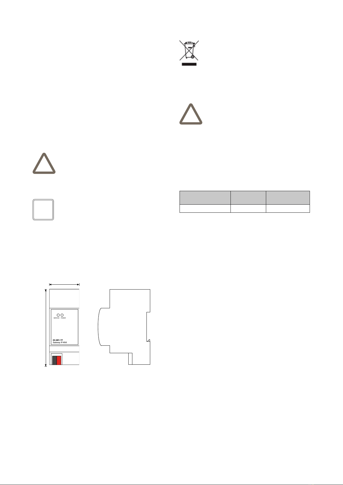
36
90,5
Note! The conguration and commissioning activities of the Kon-
nect4 server device require specialized skills on the KNX net-
work and knowledge of the specic automation project carried
out with ETS. To acquire these skills, it is essential to participate
in the courses organized at KNX certied training centers. For
further information: www.knx.it
Dimensions [mm]
i
The products described in this technical sheet at the end
of its useful life are classied as waste from electronic
equipment according to the European Directive 2012/19
/ EU (RAEE recast), implemented in Italy with Legislative
Decree no. 49 of 14 March 2014, and cannot be transfer-
red to unsorted municipal solid waste.
Warning! Incorrect disposal of the product can cause serious
damage to the environment and human health. For correct di-
sposal, inquire about the collection and treatment methods pro-
vided by the local authorities.
Document
This technical sheet refers to the A1.0 release of ekinex®
devices cod. EK-BR1-TP and is available for download
on the website www.ekinex.com in PDF (Portable Data
Format) format.
Warnings
• Installation, electrical connection, conguration and
commissioning of the device may only be carried out
by qualied personnel in accordance with the applica-
ble technical regulations and the laws in force in the
respective countries
• The device may not be used in safety applications. Ho-
wever, the device may be used for auxiliary signalling
functions
• Opening the housing of the device results in the imme-
diate interruption of the warranty period
• In the event of tampering, compliance with the essential
requirements of the applicable directives for which the
device has been certied is no longer guaranteed
• Defective ekinex® KNX devices must be returned to the
manufacturer at the following address: Ekinex S.p.A.,
Via Novara 37 - I-28010 Vaprio d’Agogna NO
Other useful informations
• This technical data sheet is addressed to installers, sy-
stem integrators and designers
• For more information on the product, you can con-
tact ekinex® technical support at the e-mail ad-
dress: [email protected] or consult the website
www.ekinex.com
• Each ekinex® device has a unique serial number on
the label. The serial number can be used by installers
and system integrators for documentation purposes
and must be added to any communication addressed
to ekinex® technical support in case of equipment mal-
function
• ekinex® is a registered trademark of Ekinex S.p.A.
• KNX® ed ETS® sono marchi registrati da KNX Asso-
ciation cvba, Bruxelles
© Ekinex S.p.A. 2021. The company reserves the right to make
changes to this technical documentation without notice.
Approvals
The products complie with the Low Voltage Directive
(2014/35 / EU) and the Electromagnetic Compatibility Di-
rective (2014/30 / EU). Tests carried out in accordance
with EN 50491-5-1: 2010, EN 50491-5-2: 2010.
Maintenance
The devices are maintenance-free. To clean them, use
a dry cloth. The use of solvents or other aggressive sub-
stances is absolutely to be avoided.

Other manuals for KONNECT4

1

This manual suits for next models

1

Other Ekinex Recording Equipment manuals

Ekinex EK-IE1-SEC-TP User manual

Ekinex

Ekinex EK-IE1-SEC-TP User manual

Ekinex EK-CG2-TP User manual

Ekinex

Ekinex EK-CG2-TP User manual

Ekinex EK-CF2-TP Instructions for use

Ekinex

Ekinex EK-CF2-TP Instructions for use

Ekinex EK-EH2-TP User manual

Ekinex

Ekinex EK-EH2-TP User manual

Ekinex KONNECT4 Instruction sheet

Ekinex

Ekinex KONNECT4 Instruction sheet

Ekinex EK-CG2-TP Instructions for use

Ekinex

Ekinex EK-CG2-TP Instructions for use

Popular Recording Equipment manuals by other brands

M-Audio Keystation 49e user guide

M-Audio

M-Audio Keystation 49e user guide

Symetrix 402 user guide

Symetrix

Symetrix 402 user guide

Roland V-Bass VB-99 Features guide

Roland

Roland V-Bass VB-99 Features guide

Alto Acom2 user guide

Alto

Alto Acom2 user guide

Nektar SE49 user guide

Nektar

Nektar SE49 user guide

MDF AM1 user manual

MDF

MDF AM1 user manual

SYAC-TB DIGIEYE MOBILE Quick setup

SYAC-TB

SYAC-TB DIGIEYE MOBILE Quick setup

BVR Instruments BASS DRUM manual

BVR Instruments

BVR Instruments BASS DRUM manual

Steinberg UR816C Startup guide

Steinberg

Steinberg UR816C Startup guide

Dictaphone Walkabout Express operating instructions

Dictaphone

Dictaphone Walkabout Express operating instructions

JVC HR-V610EX Service manual

JVC

JVC HR-V610EX Service manual

Behringer XENYX CONTROL1USB quick start guide

Behringer

Behringer XENYX CONTROL1USB quick start guide

HORNER APG Alspa 8000 manual

HORNER APG

HORNER APG Alspa 8000 manual

Graco 15V337 Instructions-parts list

Graco

Graco 15V337 Instructions-parts list

Sony MSU-1000 Operation manual

Sony

Sony MSU-1000 Operation manual

Ramix PMC665 Hardware Reference and Installation Manual

Ramix

Ramix PMC665 Hardware Reference and Installation Manual

Korg MR-1000 Update guide

Korg

Korg MR-1000 Update guide

Extron electronics NetPA AT Series Setup guide

Extron electronics

Extron electronics NetPA AT Series Setup guide

manuals.online logo
manuals.online logoBrands
  • About & Mission
  • Contact us
  • Privacy Policy
  • Terms and Conditions

Copyright 2025 Manuals.Online. All Rights Reserved.