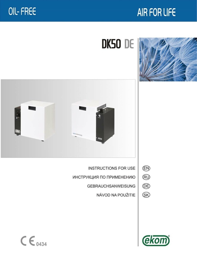
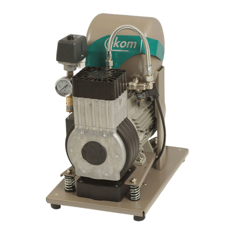
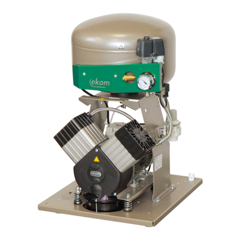
EKOM MEMBRANE DRYER User manual


NP-MD-3_11-2015 11/2015
CONTENTS................................. 1
INHALT....................................... 9
СОДЕРЖАНИЕ.......................... 17
OBSAH........................................ 25
Ed. - 3

MEMBRANE DRYER
11/2015 - 1 - NP-MD-3_11-2015
CONTENTS
IMPORTANT INFORMATION .................................................................................................................2
1.TECHNICAL DATA ..........................................................................................................2
2.PRODUCT DESCRIPTION..............................................................................................2
3.DESCRIPTION OF FUNCTIONS.....................................................................................3
INSTALLATION.......................................................................................................................................5
4.PRODUCT INSTALLATION.............................................................................................5
5.WIRING DIAGRAM ..........................................................................................................6
OPERATION..........................................................................................................................................11
6.PRODUCT OPERATION ...............................................................................................11
MAINTENANCE.....................................................................................................................................11
7.MAINTENANCE SCHEDULE.......................................................................................11
8.MAINTENANCE ............................................................................................................11
9.TROUBLESHOOTING AND REPAIRS.........................................................................12
GUARANTEE.........................................................................................................................................49

MEMBRANE DRYER
NP-MD-3_11-2015 - 2 - 11/2015
IMPORTANT INFORMATION
1. TECHNICAL DATA
Quantity of dry air
at 5 bar Up to 60 lit.min-1 Up to 120 lit.min-1 Up to 270 lit min
Nominal voltage 115V± 10%
230 V ± 10%
3x400 V ± 10%
frequency 50 - 60 Hz
Rated power 0,15A 0,15A
0,30 (for DK50 2x4VR/110)
Working pressure to 10bar
Drying performance atmosferický rosný bod -20°C
Use DK50-10 / DK50 PLUS DK50 2V / DK50 2V/50
/ DK50 2V/110
DK50 4VR/50 / DK50 2x2V/110
/ DK50 2x4VR/110
Weight
kg
6 6 / 6 / 8 11 / 8 / 16
Dimensions in mm
(w x d x h) 290x310x410 / 375x235x350 375x235x350 / 420x215x360 /
450x205x420
430x190x485 / 585x205x415
/ 560x190x400
Required drying performance can only be achieved when following the defined operating
conditions!
Drying performance will decline and the achieved dew point will drop if the dryer is operated
at any pressure below the minimum working pressure!
Dryer operation at a pressure of 0.5 Bar below the minimum working pressure can lower the
dew point at the outlet by more than 10°C!
Drying performance will decline and the achieved dew point will drop if the dryer is operated
at any temperature above the maximum working temperature!
2. PRODUCT DESCRIPTION
A pre-filter and micro-filter are installed in front of the membrane dryer in order to capture solids and condensate
and prevent the membranes from being contaminated and to deliver compressed air of the expected quality. The
clean compressed air enters the membrane dryer and the module comprised of the bundles of membrane fibres.
As the compressed air is circulated against the hollow fibres, the water molecules are compressed against the
walls of the membrane and the outlet air is dry. Water vapour molecules that form of the walls of the membranes
must be removed. This is performed using some of the dry air exiting the module. This regeneration air is then
expanded to atmospheric pressure, removing the water vapour away from the dryer.
MEMBRANE DRYER
11/2015 - 3 - NP-MD-3_11-2015
3. DESCRIPTION OF FUNCTIONS
The compressor unit (1) pulls in outside air through the inlet filter (7) and compresses it through the cooler (9),
filter (11) and micro-filter (10) to the dryer (8) and on through the check valve (3) as dry clean air in the air tank
(2). Condensate from the filter and micro-filter is automatically drained into the collection vessel. The dryer
provides continuous drying of the compressed air.
1. Compressor motor
2. Air tank
3. Check valve
4. Pressure switch
5. Safety valve
6. Manometer
7. Input filter
8. Dryer
9. Cooler
10. Micro-filter
11. Filter
12. Solenoid valve
13. Magnetic holder
14. Bottle
15. Check valve
DK50-10 Z/M
DK50 PLUS/M
15

MEMBRANE DRYER
NP-MD-3_11-2015 - 4 - 11/2015
1.Compressor motor
2.Air tank
3.Check valve
4.Pressure switch
5.Safety valve
6.Manometer
7.Input filter
8.Dryer
9.Cooler
10.Micro-filter
11.Filter
12.Solenoid valve
13.Bottle
14.Check valve
15.Check valve
DK50 2V/M
DK50 2x2V/110/M
DK50 2V/50/M

MEMBRANE DRYER
11/2015 - 5 - NP-MD-3_11-2015
1. Compressor motor
2. Air tank
3. Check valve
4. Pressure switch
5. Safety valve
6. Manometer
7. Input filter
8. Dryer
9. Cooler
10. Micro-filter
11. Filter
12. Solenoid valve
13. Bottle
14. Check valve
15. Check valve
16. Relief valve
DK50 4VR/50/M
DK50 2x4VR/110/M
INSTALLATION
4. PRODUCT INSTALLATION
Before starting any work, disconnect the equipment from all power sources and vent the air
tank to zero!
Air dryers are installed directly by the manufacturer for the appropriate type of compressor.
The installation of such dryers on compressors that are already used and operating is completed following the
separate installation guides delivered along with the product.

MEMBRANE DRYER
NP-MD-3_11-2015 - 6 - 11/2015
DK50-10Z/M, DK50-10S/M
NPE UEV1
C
EV2 YV1 B1
NU1X1 2
FU
1/N/PE ~ 230 V 50..60 Hz
SP
40°C p >
ST
34X2
2PE 3
1
M
Z1
Z2 U2
U1
150°C
1/N/PE ~ 110 V 60 Hz
C
N
PE UEV1 EV2 YV1 B1 B2
C
FU
X1
NU1234X2
2
PE 3
1
SP
40°C p >
ST M
Z1
Z2 U2
U1
150°C
DK50-10Z/M, DK50-10S/M
ELECTRIC OBJECT OF 1st CAT.
B TYPE
ELECTRIC OBJECT OF 1st CAT.
B TYPE
ELEKTRICKÝ PREDMET TR. I
1/N/PE ~ 230V 50Hz
TYP B
EV2
N
PE UEV1 CBYV1
NU3
124
FA
X1
p >
3
1
2
PE
U1
U2Z2
Z1
150°C
SP M
40°C
ST
CB1
25. 10. 2012
4U
N3
2
1
FA1
40°C
ST1
1/N/PE ~ 115V 60 Hz
p >
SP1
X1
1
M1
M
EV2EV1
GNYE
GY
BN
BK
CB2
U
N
PE
YV1
ELEKTRICKÝ PREDMET TR. I
TYP B
Before connecting the dryer to the air tank used on a compressor without a dryer, the internal surface of the air
tank must be properly cleaned and all condensed liquids must be completely removed.
The electrical portion of the dryer is then to be connected to the compressor following the electrical schematic
pursuant to valid regulations.
ATTENTION!
If the dryer fan cannot be connected to a separate electrical circuit used for the pressure switch and the
temperature switch (switching the fan for when the ambient temperature rises), it must be connected to terminals
1 and 2 on the terminal strip.
5. WIRING DIAGRAM
DK50 PLUS/M
X1 Terminal
ST Thermo switch
SP Pressure switch
M Motor
FA Breaker
YV1 Solenoid valve
EV1 Fan of compressor
EV2 Fan of dryer
CB1, CB2 Capacitor
1/N/PE ~ 230 V 50..60 Hz
ELECTRIC OBJECT OF 1st.CAT
TYPE B
1/N/PE ~ 115 V / 60 Hz
ELECTRIC OBJECT OF 1st.CAT
TYPE B

MEMBRANE DRYER
11/2015 - 7 - NP-MD-3_11-2015
26. 11. 2013
ELEKTRICKÁ SIE TN-S [TN-C-S]
3/N/PE ~ 400/230 V 50 Hz
DK50 2V/110/M
ELEKTRICKÝ PREDMET TR. 1
TYP B
40°C
ST1
13
24
FA1
N
p >
SP1
N1PE X1
PE
3M
M1 EV1
A1 24
A2 1 3
KM1
U
6
5
5
6
04
03
VW
2
PE N
150°C
YV1
SUŠIÈ
EV5
DK50 2V/110/M
40°C
ST1
13
24
FA1
N
1UN2
3PE X1
PE A2 2 4
A1 13
KM1
U
N
PE
22. 11. 2013
EV1
M1
1M
B1
C
p >
SP EV3 PH*
0000
h
* - len pre 10 bar
YV1
1/N/PE ~ 230V 50..60 Hz
ELEKTRICKÝ PREDMET TR. I TYP B
DK50 2V/M
DK50 2V/M
EV1
2
PE N U
NU1
FA
40°C p >
ST1
EV2 YV1
X1
3
1
CB1
M
SP M1
1/N/PE ~ 230 V 50..60 Hz
ELECTRIC OBJECT OF 1st.CAT
TYPE B
X1 Terminal
ST Thermo switch
SP Pressure switch
M Motor
FA Breaker
YV1 Solenoid valve
EV1 Fan of compressor
EV2, EV3*, EV5 Fan of dryer
CB1 Capacitor
KM1 Contactor
PH* Hour meter
1/N/PE ~ 230 V 50..60 Hz
ELECTRIC OBJECT OF 1st.CAT
TYPE B
3/N/PE ~ 400/230 V 50 Hz
MAINS TN-S [TN-C-S]
ELECTRIC OBJECT 1ST CAT.
TYPE B
* only for 10bar

MEMBRANE DRYER
NP-MD-3_11-2015 - 8 - 11/2015
26. 11. 2013
ELEKTRICKÁ SIE TN-S [TN-C-S]
3/N/PE ~ 400/230 V 50 Hz
DK50 2x2V/110/M
ELEKTRICKÝ PREDMET TR. 1
TYP B
40°C
ST1
13
24
FA1
N
p >
SP1
N1PE X1
PE
3M
M1 EV1
A1 24
A2 13
KM1
U
6
5
5
6
04
03
VW
2
PE N
150°C
YV1
SUŠIÈ EV3
13
24
FA2
3M
M2 EV2
A1 24
A2 13
KM2
6
5
5
6
04
03
150°C
DK50 2x2V/110/M
40°C
ST1
13
24
FA1
N
1UN2
3PE X1
PE
13
24
FA2
A2 2 4
A1 13
KM1 KM2
1UN
PS 2V2
A2 2 4
A1 13
U
N
PE
22. 11. 2013
EV1 YV1
M1
1M
B1
C
p >
SP EV2
M2
1M
B2
C
EV3 PH*
0000
h
* - len pre 10 bar
1/N/PE ~ 230V 50..60 Hz
ELEKTRICKÝ PREDMET TR. I TYP B
M1,M2 Motor of compressor
EV1, EV2 Fan of compressor
KM1,KM2 Contactor
FA1, FA2 Breaker
ST1 Thermo switch
SP Pressure switch
EV3 Fan of dryer
X1 Terminal with fuses
YV1 Solenoid valve of compressor
M1,M2 Motor of compressor
EV1, EV2 Fan of compressor
KM1,KM2 Contactor
FA1, FA2 Breaker
ST1 Thermo switch
SP Pressure switch
EV3 Fan of dryer
X1 Terminal with fuses
YV1 Solenoid valve of compressor
PS 2V2 PCB
PH* Hour meter
1/N/PE ~ 230 V 50..60 Hz
ELECTRIC OBJECT OF 1st.CAT
TYPE B
3/N/PE ~ 400/230 V 50 Hz
MAINS TN-S [TN-C-S]
ELECTRIC OBJECT 1ST CAT.
TYPE B
* only for 10bar

MEMBRANE DRYER
11/2015 - 9 - NP-MD-3_11-2015
DK50 2V / 50 / MD
13
24
FA1
N
p >
SP1
A2 24
A1 1 3
KM1
M1
1M
B1
C
YV1
XC1
2/L
N
1/L
PE
PE
X1
PE 2 3N
N1
PH*
0000
h
N U PE
40°C
ST1 EV1 EV3
* - len pre 10 bar
DK50 2V / 50 / MD
FA1
WVPENU
13
24
5
6
XC1
2/L
N
1/L
PE
PE
X1
PE 2 3
N
N1
N
KM1
A2 24
A1 13
6
5
03
04
EV1
3M
M1
150°C
PH*
0000
h
YV1
p >
SP1
40°C
ST1
* - len pre 10 bar
EV3
22. 11. 2013
SP Pressure switch
EV1 Fan of compressor
ST1 Thermo switch
EV3 Fan of dryer
M1 Motor of compressor
FA1 Breaker
YV1 Solenoid valve
KM1 Contactor
X1 Terminal
PH1* Hour counter
XC1 Connector
CB1 Capacitor
1/N/PE ~ 230V 50..60 Hz
ELECTRIC OBJECT OF 1ST. CAT TYPE B
SP Pressure switch
EV1 Fan of compressor
ST1 Thermo switch
EV3 Fan of dryer
M1 Motor of compressor
FA1 Breaker
YV1 Solenoid valve
KM1 Contactor
X1 Terminal
PH1* Hour counter
XC1 Connector
3/N/PE ~ 400/230 V 50 Hz
MAINS TN-S [TN-C-S]
ELECTRIC OBJECT 1ST CAT.
TYPE B
1/N/PE ~ 230 V 50..60 Hz
ELECTRIC OBJECT OF 1st.CAT
TYPE B
3/N/PE ~ 400/230 V 50 Hz
MAINS TN-S [TN-C-S]
ELECTRIC OBJECT 1ST CAT.
TYPE B
* only for 10bar
* only for 10bar

MEMBRANE DRYER
NP-MD-3_11-2015 - 10 - 11/2015
DK50 4VR/50S/M (MD)
2
1
4
35
2
1
4
3
6
5
04
03
A2
A1
Q11
M
6
150°C
1
3
2
42
1
p >
40°C
B1 B2
E1 E2
12
PE
12
M10
21
F1
3/N/PE ~ 400 V 50 Hz
ELEKTRICKÁ SIETN-S [TN-C-S]
ELEKTRICKÝ PREDMET TR. I
TYP B
X1:2
X1:1.1
PE
3~
2TB1
2TB2
L1
L2
L3
N
PE PE
F3
X1:1.2
E5
12
PE
X1:3
5G1
h
P1
2
N
1
3
PE
X2
PE
PE
111
bk bk bk
bn
bn bk gy
X3
bu
PE
PE
M1
gnye
3/N/PE ~ 400 V 50 Hz
ELEKTRICKÁ SIETN-S [TN-C-S]
ELEKTRICKÝ PREDMET TR. I
TYP B
2
1
4
35
2
1
4
3
6
5
04
03
A2
A1
Q1
M
6
2
1
4
3
6
5
04
03
A2
A1
Q2
M
p >
40°C
B1 B2
E1 M12
F1
PE
3~3~
L1
L2
L3
N
PE
X1:2
2
1
4
35
6
F2
PE
M1 M2
PS2
U1 N
1
2
3
PE
N
X2
K3
PE PE PE PE
L1
L2
L3
N
PE
X3
X1:1
F3 /1.6A
F3
E2 E3 E4
PE
E5 E6
P1
h
~~
PE
DK50 2x4VR/110S/M(MD)
B1 Pressure switch
E1, E2 Compressor fan
E5 Dryer fan
B2 Temperature switch
M1 Compressor motor
F1 Breaker
F3 Fuse
M10 Solenoid valve
Q11 Contactor
X1 Terminal strip
X2 Connector
P1 Hour counter
E1 - E4 Fan of compressor
E5 – E6 Fan of cooler
M12 Solenoid valve
X1 Terminal with fuse
F3 Fuse
X2 Connector
M1,M2 Motor of compressor
F1,F2 Breaker
K3 PCB
Q1,Q1 Contactor
B2 Thermo switch
B1 Pressure switch
P1 Hour meter
3/N/PE ~ 400/230 V 50 Hz
MAINS TN-S [TN-C-S]
ELECTRIC OBJECT 1ST CAT.
TYPE B
3/N/PE ~ 400/230 V 50 Hz
MAINS TN-S [TN-C-S]
ELECTRIC OBJECT 1ST CAT.
TYPE B

MEMBRANE DRYER
11/2015 - 11 - NP-MD-3_11-2015
OPERATION
6. PRODUCT OPERATION
Proper dryer operation depends on the compressor activity and does not require any operation. The pressure
vessel does not need to be drained as the compressed air into the air tank is already dried.
The working pressure settings for the pressure switch set by the manufacturer cannot be changed. Compressor
operation at lower working pressures than the switching pressure is evidence that the compressor is overloaded
(high air consumption) caused by an appliance, a failed seal in the air line, compressor problem or dryer.
Before connecting the dryer to the air tank used on a compressor without a dryer, the internal surface of the air
tank must be properly cleaned and all condensed liquids must be completely removed. The electrical portion of
the dryer is then to be connected to the compressor following the electrical schematic pursuant to valid
regulations.
MAINTENANCE
7. MAINTENANCE SCHEDULE
Time interval Maintenance that must be performed Chapter Performed by
1 x year • Replacement of filter element in filter
and micro-filter 8 operating staff
8. MAINTENANCE
Before proceeding, depressurize the air tank to zero and disconnect the appliance from the
electrical mains!
The equipment has been constructed and produced to keep maintenance to a minimum.
Replacement of filter element in filter
Loosen a safety-catch (1) on a filter regulator by pulling it down.
Turn the container slightly (2) and pull out.
Unbolt the filter holder (3).
Change the filter bed (4), bolt the filter holder.
Put the filter container on and secure it by turning it until the
safety-catch is fixed.
Compressor Filter Order number Filter insert Order number
DK50-10,
DK50 PLUS, DK50 2V,
DK50 2V/50,DK50 2V/110
AF 30-F02C 025200005-000 AF 30P-060S 5 m 025200061-000
DK50 2x2V/110,
DK50 4VR/50,
DK50 2x4VR/110
AF 40P–060S 025200215-000 AF 40P–060S 5 m 025200079-000
1
24
3

MEMBRANE DRYER
NP-MD-3_11-2015 - 12 - 11/2015
Replacement of filter element in micro-filter
Loosen a safety-catch (1) on a micro filter by pulling it down.
Turn the container slightly (2) and pull out.
Unbolt the filter (3).
Change and bolt the filter bed.
Put the filter container on and secure it by turning it until the
safety-catch is fixed.
The equipment, in particular the cooling fan must be kept clean to ensure the long-term efficiency of the cooler –
the cooling fins must be cleaned occasionally to remove any dust.
9. TROUBLESHOOTING AND REPAIRS
All repairs must be completed by trained service staff and organizations that are certified for
such tasks.
Before proceeding, depressurize the air tank to zero and disconnect the appliance from the
electrical mains.
Drying unit is not drying:
Cooling fan not working - Replace the fan and check function
Dryer - possible damage
Damaged dryer - Replace the dryer
Automatic condensate drain is plugged - Clean / replace
on filters
Plugged filter element in filter or micro-filter - Replace old element with a new element
The internal surfaces of the air tank must be cleaned and all condensed water must be completely removed after
a dryer fault.
Check the humidity of the outlet air from the air tank (see Chapter 1 - Technical Data) to ensure the
connected equipment is protected from damage!
The manufacturer reserves the right to make changes to the equipment without notice. Any changes
made will not affect the functional properties of the equipment.
Compressor Micro-filter Order number Filter insert Order number
DK50-10,
DK50 PLUS, DK50 2V,
DK50 2V/50,DK50 2V/110
AFM 30-F02C 025200007-000 AFM 30P-060AS 0,3 m 025200076-000
DK50 2x2V/110,
DK50 4VR/50,
DK50 2x4VR/110
AFM 40–F03C 0252002156-000 AFM 40P–060AS 5 m 025200080-000
23
1

MEMBRANE DRYER
11/2015 - 13 - NP-MD-3_11-2015
INHALT
WICHTIGE INFORMATIONEN ............................................................................................................. 14
1.TECHNISCHE DATEN .................................................................................................. 14
2.PRODUKTBESCHREIBUNG ........................................................................................ 14
3.FUNKTION..................................................................................................................... 15
INSTALLATION .................................................................................................................................... 17
4.PRODUKTINSTALLATION............................................................................................ 17
5.SCHALTPLÄNE............................................................................................................. 18
BEDIENUNG ......................................................................................................................................... 23
6.PRODUKTBEDIENUNG................................................................................................ 23
WARTUNG ............................................................................................................................................ 23
7.WARTUNGSPLAN ........................................................................................................ 23
8.WARTUNG .................................................................................................................... 23
9.FEHLERBEHEBUNG UND REPARATUREN ............................................................... 24
GARANTIEBRIEF ................................................................................................................................. 49

MEMBRANE DRYER
NP-MD-3_11-2015 - 14 - 11/2015
WICHTIGE INFORMATIONEN
1. TECHNISCHE DATEN
Menge an Trockenluft
bei 5 bar bis 60 lit.min-1 bis 120 lit.min-1 bis 270 lit min
Nennspannung 115V± 10%
230 V ± 10%
3x400 V ± 10%
Frequenz 50 - 60 Hz
Nennleistung 0,15 A 0,15 A
0,30 A (für DK50 2x4VR/110)
max. Arbeitsdruck bis 10 bar
Trockenleistung Atmosphärischer Taupunkt -20°C
Benutzung DK50-10 / DK50 PLUS DK50 2V / DK50 2V/50
/ DK50 2V/110
DK50 4VR/50 / DK50
2x2V/110
/ DK50 2x4VR/110
Gewicht 6 6 / 6 / 8 11 / 8 / 16
Maße mm
(Höhe x Breite x Tiefe) 290x310x410 / 375x235x350
375x235x350 /
420x215x360 /
450x205x420
430x190x485 / 585x205x415
/ 560x190x400
Die benötigte Trockenleistung kann nur erreicht werden, wenn die festgelegten
Arbeitsbedingungen eingehalten werden!
Die Trockenleistung fällt ab und der erreichte Taupunkt fällt, wenn der Trockner mit einem
Druck unter dem minimalen Arbeitsdruck bedient wird!
Die Bedienung des Trockners bei einem Druck von 0,5 bar unter dem minimalen
Arbeitsdruck kann den Taupunkt beim Abfluss um mehr als 10°C reduzieren!
Die Trockenleistung fällt ab und der erreichte Taupunkt fällt, wenn der Trockner mit einer
Temperatur, die über der maximalen Arbeitstemperatur liegt, bedient wird!
2. PRODUKTBESCHREIBUNG
Vor dem Membrantrockner sind ein Vor- und ein Mikrofilter befestigt, um Feststoffe und Kondensat aufzufangen
und um zu verhindern, dass die Membranen verschmutzt werden und um Druckluft in der erwarteten Qualität zu
liefern. Die saubere Druckluft dringt in den Membrantrockner ein, dessen Modul aus einer Anzahl von
Membranfasern besteht. Während die Druckluft die hohlen Fasern umkreist, werden die Wassermoleküle gegen
die Wände der Membran gedrückt und die Abluft ist somit trocken.
Wasserdampfmoleküle, die sich an den Wänden der Membran bilden, müssen entfernt werden. Dies wird
erreicht, indem man etwas von der trockenen Luft, die aus dem Modul entweicht, benutzt. Diese regenerierte
Luft wird dann zu Atmosphärendruck ausgedehnt, wodurch Wasserdampf aus dem Trockner entfernt wird.

MEMBRANE DRYER
11/2015 - 15 - NP-MD-3_11-2015
3. FUNKTION
Kompressor mit Membrantrockner
Die Kompressoreinheit (1) zieht durch den Einlauffilter (7) Außenluft ein und presst sie durch den
Trocknerkühler (9), Filter (11) und Mikrofilter (10) zum Trockner (8) und weiter durch das Absperrventil (3) als
trockene, sauber Luft in den Druckluftspeicher (2). Das Kondensat aus dem Filter und Mikrofilter wird
automatisch in den Sammelbehälter abgelassen. Der Trockner trocknet ständig Druckluft.
1. Kompressormotor
2. Druckluftspeicher
3. Rückschlagventil
4. Druckschalter
5. Sicherheitsventil
6. Druckmesser
7. Eingangsfilter
8. Trockner
9. Trocknerkühler
10. Mikrofilter
11. Filter
12. Magnetventil
13. Magnetständer
14. Flasche
15. Rückschlagventil
DK50-10 Z/M
DK50 PLUS/M
15

MEMBRANE DRYER
NP-MD-3_11-2015 - 16 - 11/2015
1. Kompressormotor
2. Druckluftspeicher
3. Rückschlagventil
4. Druckschalter
5. Sicherheitsventil
6. Druckmesser
7. Eingangsfilter
8. Trockner
9. Trocknerkühler
10. Mikrofilter
11. Filter
12. Magnetventil
13. Flasche
14. Rückschlagventi
15. Rückschlagventil
DK50 2V/M
DK50 2x2V/110/M
DK50 2V/50/M

MEMBRANE DRYER
11/2015 - 17 - NP-MD-3_11-2015
1. Kompressormotor
2. Druckluftspeicher
3. Rückschlagventil
4. Druckschalter
5. Sicherheitsventil
6. Druckmesser
7. Eingangsfilter
8. Trockner
9. Trocknerkühler
10. Mikrofilter
11. Filter
12. Magnetventil
13. Flasche
14. Rückschlagventi
15. Rückschlagventil
16. Überdruckventil
DK50 4VR/50/M
DK50 2x4VR/110/M
INSTALLATION
4. PRODUKTINSTALLATION
Bevor irgendeine Arbeit begonnen wird, trennen Sie das Gerät von allen Stromquellen und
lassen Sie die Luft im Luftbehälter auf Null ab!
Der Lufttrockner wird direkt durch den Hersteller für den passenden Kompressortyp installiert.
Die Installation eines solchen Trockners auf Kompressoren, die bereits benutzt werden und in Betrieb sind, wird
entsprechend der separaten Installationsanleitungen, die zusammen mit dem Produkt geliefert werden,
abgeschlossen.

MEMBRANE DRYER
NP-MD-3_11-2015 - 18 - 11/2015
Bevor der Trockner mit dem Luftbehälter, der auf einem Kompressor ohne einen Trockner benutzt wird,
verbunden wird, muss die innere Oberfläche des Luftbehälters richtig gesäubert werden und alle kondensierten
Flüssigkeiten müssen vollständig entfernt werden.
Die Stromversorgung des Trockners wird dann entsprechend des elektrischen Schemas gemäß der gültigen
Regeln an den Kompressor angeschlossen
POZOR !
Kann der Trockenventilator nicht an einen separaten elektrischen Kreislauf, der für den Druck- und den
Temperaturschalter benutzt wird (Anschalten des Ventilators, wenn die umgebende Temperatur steigt),
angeschlossen werden, muss er mit Terminal 1 und 2 auf der Anschlussleiste verbunden werden.
5. SCHALTPLÄNE
DK50 PLUS/M DK50 PLUS/M
ELEKTRICKÝ PREDMET TR. I
1/N/PE ~ 230V 50Hz
TYP B
EV2
N
PE UEV1 CBYV1
NU3
124
FA
X1
p >
3
1
2
PE
U1
U2Z2
Z1
150°C
SP M
40°C
ST
CB1
25. 10. 2012
4U
N3
2
1
FA1
40°C
ST1
1/N/PE ~ 115V 60 Hz
p >
SP1
X1
1
M1
M
EV2EV1
GNYE
GY
BN
BK
CB2
U
N
PE
YV1
ELEKTRICKÝ PREDMET TR. I
TYP B
1/N/PE ~ 115V / 60Hz
ELEKTRISCHES OBJEKT DER 1. KAT.
TYP B
1/N/PE ~ 230 V 50/60 Hz
ELEKTRISCHES OBJEKT DER 1. KAT.
TYP B
X1 Anschlussklemme
ST Thermoschalter
SP Druckschalter
M Motor
FA Ausschalter
YV1 Magnetventil
EV1 Ventilator des Kompressors
EV2 Ventilator des Trockners
CB1 Kondensator
DK50-10Z/M, DK50-10S/M
NPE UEV1
C
EV2 YV1 B1
NU1X1 2
FU
1/N/PE ~ 230 V 50..60 Hz
ELEKTRICKÝ PREDMET TR. I
TYP B
SP
40°C p >
ST
34X2
2PE 3
1
M
Z1
Z2 U2
U1
150°C
1/N/PE ~ 110 V 60 Hz
ELEKTRICKÝ PREDMET TR. I
TYP B
C
N
PE UEV1 EV2 YV1 B1 B2
C
FU
X1
NU1234X2
2PE 3
1
SP
40°C p >
ST M
Z1
Z2 U2
U1
150°C
DK50-10Z/M, DK50-10S/M
1/N/PE ~ 115V / 60Hz
ELEKTRISCHES OBJEKT DER 1. KAT.
TYP B
1/N/PE ~ 115V / 60Hz
ELEKTRISCHES OBJEKT DER 1. KAT.
TYP B
Table of contents
Languages:
Other EKOM Medical Equipment manuals

EKOM
EKOM DK50 D User manual

EKOM
EKOM DK50 DS User manual

EKOM
EKOM invent DK50 DI User manual

EKOM
EKOM DK50 2V/110 User manual

EKOM
EKOM DK50 2V S Owner's manual

EKOM
EKOM DUO Owner's manual

EKOM
EKOM DK50 DE User manual

EKOM
EKOM DK50 2V/50/M User manual

EKOM
EKOM MONZUN M1a User manual

EKOM
EKOM DK50 2V/M MOBILE User manual