HealthCo Milla B430 User manual

W: www.healthcoltd.co.uk E: [email protected]
Milla B430 by HealthCo
Compact Ultra low Bed
User Manual
DEALERS: This manual MUST be given to the user of the bed.
USER: Before using this bed, read this manual and save for future reference.

1
Table of Contents
WARNINGS ......................................................................................................................................................2
DECLARIATION –ELECTROMAGNETIC EMSSIONS.............................................................................................3
TECHNICAL SPECIFICATION ..............................................................................................................................4
ASSEMBLY INSTRUCTIONS ...............................................................................................................................5
1. UNPACKING THE BED................................................................................................................................5
2.1 ASSEMBLING THE BED ..............................................................................................................................6
2.2 ASSEMBLING THE BED DECK.....................................................................................................................6
2.3 ASSEMBLING THE HEAD/FOOT BOARD ONTO THE BED............................................................................7
2.4 INSTALLING THE MATTRESS RETAINING SYSTEM .....................................................................................7
2.5 INSTALLING THE HAND PENDANT CLIP.....................................................................................................8
2.6 CONNECTING CABLES TO THE CONTROL BOX...........................................................................................8
2.7 INSTALLING BATTERY BACKUP (OPTIONAL)...............................................................................................10
2.8 INSTALLING THE RAILS (OPITONAL)...........................................................................................................11
EQUIPMENT OPERATION ...............................................................................................................................13
1. POSITIONING THE BED............................................................................................................................13
2. USING THE CONTROLLER ........................................................................................................................13
3. LEVELING THE LEG REST..........................................................................................................................14
4. FOLDING AND TRANSPORTING THE BED ................................................................................................15
TROUBLESHOOTING GUIDE............................................................................................................................16
SERVICE RECORD ...........................................................................................................................................17

2
WARNINGS
•DO NOT exceed maximum weight limitation of the bed. The maximum safe working load
(SWL) of the bed is 180 kg. The suggested patient weight is 145 kg. but varies based on
the accessories on the bed.
•The beds are intended for users who fully understand the content of this manual and is
not intended for use by children.
•DO NOT operate your bed until it is fully assembled and checked. To avoid injury, DO NOT
attempt to remove the bed from the carton without assistance.
•DO NOT use accessories that are not designed or approved for use with the bed. Use only
manufacturer approved parts and accessories. DO NOT make modifications to the bed
without authorisation from the manufacturer. Doing so will void the warranty. Serious
harm or death may result from the use of improper parts or accessories.
•The bed is NOT a transport device. The wheels on the bed are for positioning the bed
only. The wheels must be locked at all times when the patient is on the bed.
•Never permit more than one person on the bed at one time.
•Ensure that the individual is properly positioned. The body weight must be evenly
distributed over the sleeping surface. Caution should be used when transferring the
individual to and from the bed.
•ALWAYS keep hands and feet away from the bottom of the bed and any moving parts to
avoid injury. Due to the low bed clearance, extreme caution should be used as under bed
space and/or moving parts can create crush or pinch points.
•DO NOT operate the bed with any items under the bed.
•ONLY use appropriate mattresses and ALWAYS adjust the mattress retainer system
accordingly to ensure the mattress is fixed in place. The mattress must fit the frame
properly to avoid any entrapment issues. The wrong size mattress may cause serious
harm or death.
•Inspect the castors every six months to check for tightness and wear.
•DO NOT, under any circumstances, cut or remove the earth pin from any plug. ONLY use
an extension cable having the same or higher electrical rating as the device being
connected.
•Cables should be routed and secured properly to ensure they are not damaged during
normal operation. DO NOT use if any cable is cut, frayed or loosely connected to the
device. Cables may be damaged by inappropriate handling, e.g. by kinking, shearing or
other mechanical damages. The cables are only replaceable by authorised service
personnel.
•When moving the bed ensure the power cable and pendants are secured. Ensure that the
castors do not roll over the cables. Do not use the assist bars or rails as handles when
moving the bed.

3
•DO NOT attempt to open the pre-sealed actuator or obtain local service, for it will VOID
the warranty and might result in damage. Consult your dealer or manufacturer for further
information.
WHEN USING RAILS OR ASSIST BARS:
•Before operating, ensure that the bed rails/bars are assembled and installed correctly as
instructed.
•DO NOT apply side pressure to the bed rails/bars. This could deform or break the bed
rails. This could result in personal injury and damage to the bed rails.
•DO NOT use the bed rails/bar as a push handle for moving the bed. This could deform or
break the bed rails.
•DO NOT use the bed rails/bar if proper installation cannot be achieved. Contact your
dealer or manufacturer.
DECLARIATION –ELECTROMAGNETIC EMSSIONS
The B430 medical bed is intended for use in the electromagnetic environment in which
radiated RF disturbances are controlled. The customer or the user of the B430 medical bed
can help prevent electromagnetic interference by maintaining a minimum distance between
portable and mobile RF communications equipment (transmitters) and the B430 medical bed
and according to the maximum output power of the communications equipment.
Special considerations should be given to proximity of B430 medical bed and patients who
have a cardiac pacemaker, implanted defibrillator, or other implanted metallic or electronic
device, because this may cause electrical interference, or death.
Interference to electronic equipment may occur in the vicinity of devices marked with this
symbol:

4
TECHNICAL SPECIFICATION
Operating Range
Bed Height
65 mm - 650 mm
Back Rest Angle
0° - 70°
Knee Break Angle
0° - 27°
Additional Manual Leg Lift
Yes, various positions
Trendelenburg/ Reverse Trendelenburg
± 12°
Weight
Limit
Safe Working Load (SWL)
180 kg
Max. Patient Weight
145 kg
Dimensions
Sleeping Surface Dimension
Width x Length
900 mm x 2000 mm
Overall Bed Height Including head/foot board
853 mm - 1438 mm
Castor Size
75 mm
Weights
Weight IN Carton
115 kg
Weight OUT of Carton
105 kg
Electrics
Power Supply (V/PH/Hz)
100-240V/1ph/50-60Hz
Power Consumption (Max)
200 W
Number of Motors
5
Protection Class
IPX4
Insulation Class
II Type B
Duty Cycle
Interruption 10%, Max. 2 min./18min.
Battery backup
Yes, optional
Noise Level
< 50 db(a)
5
ASSEMBLY INSTRUCTIONS
1. UNPACKING THE BED
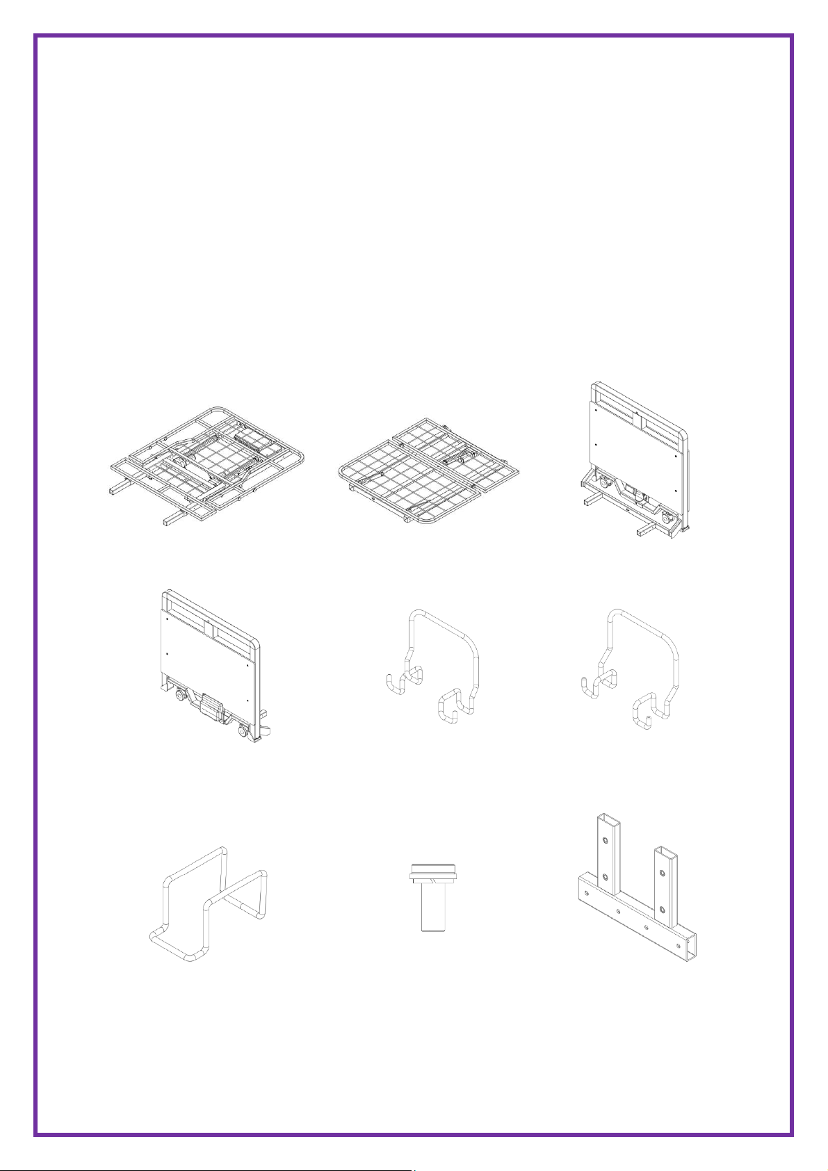
I. Unpack the components from the shipping cartons.
II. Remove any zip ties holding the components to the Bed Assembly.
III. Upon unpacking your bed, the package should contain all the following
components.
IV. Inspect the bed components for damages. If the bed is damaged, do not use the
bed and contact the manufacturer.
Upper Bed Deck x 1
Lower Bed Deck x 1
Head Board x 1
Foot Board x 1
Mattress Retainer (Sides) x 2
Mattress Retainer
(Ends) x 4
Hand Pendant Clip x 1
M8 Socket Screw x 16
(with washer & spring
washer)
Transport Bar x 2

6
Allen Wrench x 1 (5mm)
2.1 ASSEMBLING THE BED
The bed comes in with the sections (head board, foot board, upper bed deck and lower
bed deck) stacked, carefully lay each section on the floor.
2.2 ASSEMBLING THE BED DECK
1. With the bed decks positioned flat on the floor, join the upper and lower bed decks
together.
2. Secure the two decks together with two socket screws on each side.

7
2.3 ASSEMBLING THE HEAD/FOOT BOARD ONTO THE BED
1. Lift up the upper bed deck slightly and insert the head board into the main bed
frame.
2. Secure the head board to the deck with two socket screws on each side.
3. Repeat the same procedure for foot board installation.
2.4 INSTALLING THE MATTRESS RETAINING SYSTEM
1. Snap the mattress retainer onto the bed frame and push it down firmly. The
mattress retainers for the sides will be shorter than the ones for the bed ends.
2. Repeat the procedure until all six mattress retainers are installed. There should be
one retainer on either side of the bed and two on both ends of the bed.

8
2.5 INSTALLING THE HAND PENDANT CLIP
Clip the hand pendant clip over the two timber panels of the head board and push it
down firmly.
2.6 CONNECTING CABLES TO THE CONTROL BOX
Motor cables will need to be connected to the control box, located at the center of the
bed. The motors for the backrest control should already be connected.
1. Open the control box locking lid by pressing in the sides and lift it up, to expose the
connection ports.
2. The cables and the port connections are color-coded. Route the cables to their
matching port. When running the cables, ensure they are neatly tied along the bed
frame and do not interfere with the bed operation. Holes are provided on the bed
frame for cable routing.

9
Backup Battery Backrest Motor 1 Backrest Motor 2 Headboard Motor
(if applicable)
Hand Control
Footboard Motor Kneebreak Motor Underbed lighting Nursing Control
(if applicable) (if applicable)
3. Connect all cables and reinstate the locking lid, ensure there is an audible click.

10
2.7 INSTALLING BATTERY BACKUP (Optional)
1. Switch the power supply off when installing the backup battery.
2. Affix the backup battery with nuts and bolts to the left of the control box, on the
same holding plate.
3. Open the control box locking lid by pressing in the sides and lift it up, to expose the
connections ports.
4. Connect the backup battery cable to the control box. The connection port is
indicated with a battery symbol above.
5. Close the locking lid. There should be an audible click. Switch the power supply back
on.

11
2.8 INSTALLING THE RAILS (Optional)
1. Before installing the rails, the bed should be in the flat position.
2. Unclip the metal snap ring and remove the metal pins from the rail mounting
brackets.
3. Hook the rail bracket onto the edge of the bed decking. Align the rail bracket
mounting holes with the bed deck mounting holes.
4. Re-insert the metal pins through the mounting holes and secure with the snap rings.
Make sure the snap rings are positioned in the groove of the metal pins.
5. Tighten the allen screws next to the metal pins.
6. Repeat the same procedure to install the other rail.

12
Holes for Assist Bars

13
EQUIPMENT OPERATION
1. POSITIONING THE BED
To position the bed, use the castors to move the bed. Once the bed is in its desired
location, lock all castors in place.
2. USING THE CONTROLLER
The UP arrow ( ) indicates raising the corresponding parts of the bed.
The DOWN arrow ( ) indicates lowering the corresponding parts of the bed.
1. Use button 1 and 2 to adjust the backrest up or down.
2. Use button 3 and 4 to adjust the kneebreak up or down.
3. Use button 5 and 6 to adjust the backrest and kneebreak up
or down simultaneously. (Auto Contour feature)
4. Use button 7 and 8 to raise or lower the bed platform.
5. Use button 9 and 10 to tilt the bed into reversed-
trendelengburg and Trendelenburg positions.
The bed is equipped with an Entrapment Safety Measure. If the bed platform is higher
than 320mm from the floor, long press button 8 will lower the bed to 320mm. To

14
continue lowering the bed, release and long press button 8 again. Ensure no body parts
or obstacles are within the bed’s moving range.
Where a connection fault is identified and rectified, the control system will require a
reset in order to operate again. If the fault occurred on the motors for platform profiling,
lower the corresponding motor to the lowest position for reset; where the fault
occurred on the motors for bed height adjustments, raise the bed to the highest
position for reset.
3. LEVELING THE LEG REST
The end foot section can be adjusted manually to further alter the kneebreak angle.
1. Grip the end section of the bed platform. Lift up slowly to the preferred height.
Ensure there is an audible click indicating the deck is locked in position.
2. To lower the deck to its original position, first lift it up to the highest position and
slowly lay it back down.
15
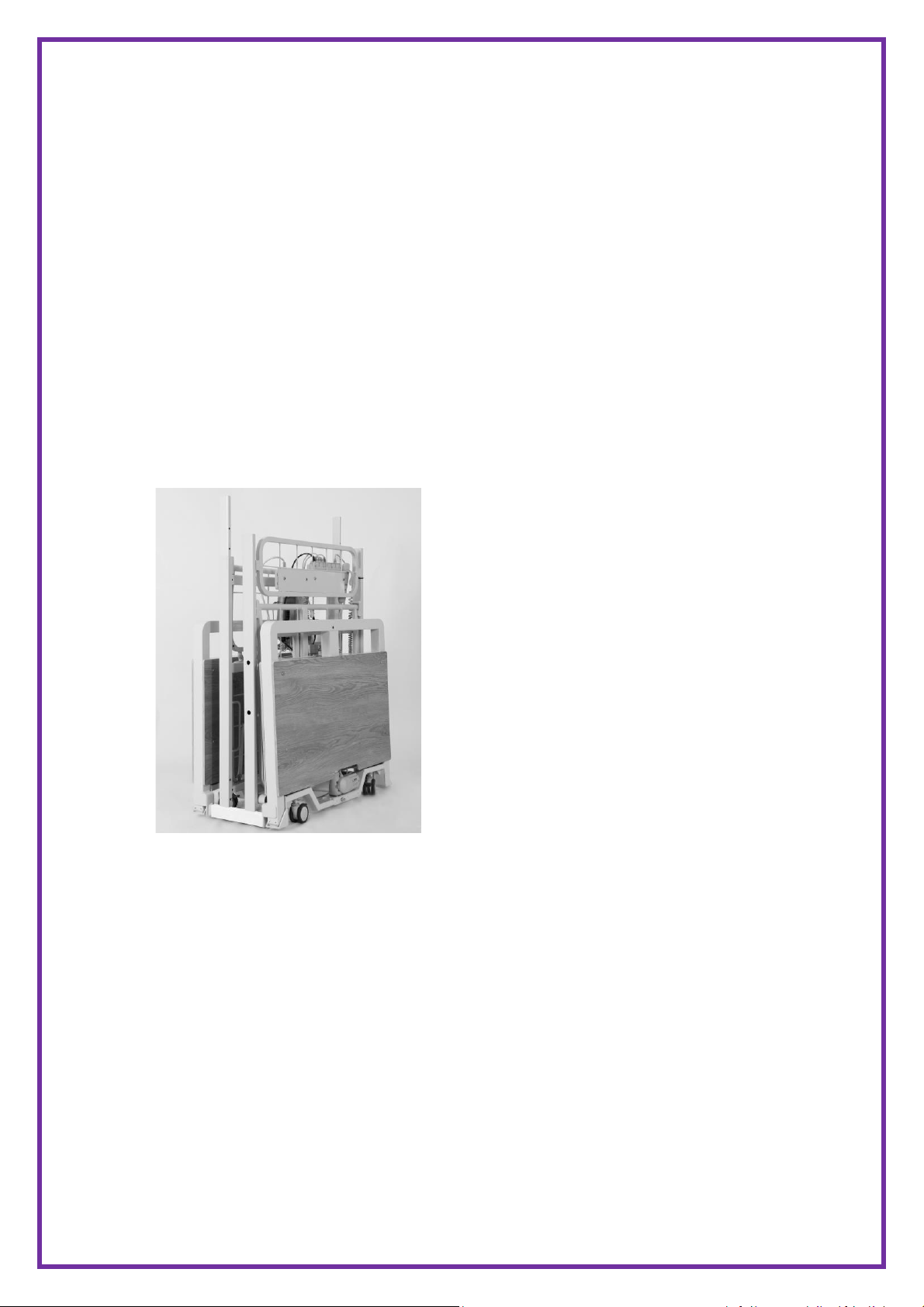
4. FOLDING AND TRANSPORTING THE BED
The bed can be disassembled and transferred in a compact manner using the transport
bars.
1. Reverse the bed installation procedure to disassemble the bed into four sections,
the head board, the foot board, the upper and lower bed decks.
2. With the tees of the transport bars pointing upwards, connect the head and
footboard to the transport bar and secure with socket screws.
3. Insert the two bed deck sections onto the transport bar tees and secure with socket
screws.
4. The folded bed can be transported with the castors on the head and foot board.
Reverse the procedure to reassemble the bed.

16
TROUBLESHOOTING GUIDE
SYMPTOMS
FAULTS
SOLUTIONS
Bed idle when hand pendant
buttons are pressed.
Adjustment may be at the
maximum or minimum
position.
Power cable not connected
or damaged.
Hand control or actuator
connectors are loose.
Actuator in need of service or
load is too high.
Control system has not been
reset after faults were fixed.
Entrapment Safety Measure is
in place.
Check if other buttons are
working.
Ensure the power cable is
properly connected to the
electrical socket and the bed.
Ensure tight connection of all
connectors or control box.
Contact your supplier for
actuator maintenance.
Refer to Equipment
Operation.
Refer to Equipment
Operation.
Castors/Brakes noisy or stiff.
Debris or fluff in bearings
Clean or replace castors.
Noisy or dry sound from
pivot points.
Needs lubrication.
Lubricate your bed.
Unusual noise from actuator.
Actuator is worn or damaged
or spindle is bent.
Replace the actuator. Contact
your supplier.
Head/footboard unstable.
Head/footboard frame not
tightly secured.
Refer to Assembly
Instructions

17
SERVICE RECORD
DATE
PERFORMED BY
CONDITION REPORT

18
DATE
PERFORMED BY
CONDITION REPORT
Table of contents
Other HealthCo Medical Equipment manuals


Popular Medical Equipment manuals by other brands


Getinge
Getinge Arjohuntleigh Nimbus 3 Professional Instructions for use

Mettler Electronics
Mettler Electronics Sonicator 730 Maintenance manual

Pressalit Care
Pressalit Care R1100 Mounting instruction

Denas MS
Denas MS DENAS-T operating manual

bort medical
bort medical ActiveColor quick guide

AccuVein
AccuVein AV400 user manual


