Bedienungsanleitung
Manual
Version: 3.4.4 / 20.09.2017
Freigabe: M. L.
Seite 2 von 4
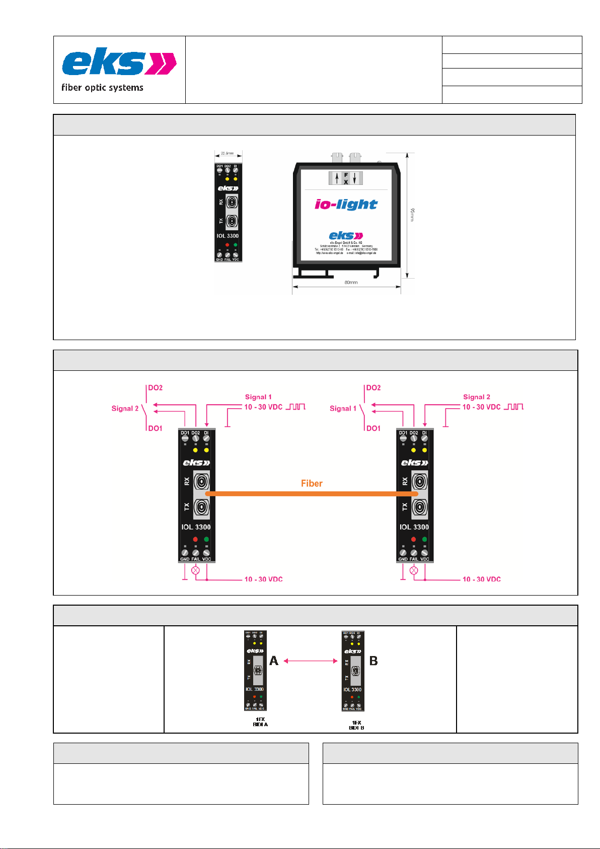
Systembeschreibung System description
Mit dem LWL-System IOL-3300 werden Schalt- oder Steuersignale über Licht-
wellenleiter übertragen.
Ein digitales Schaltsignal (12 – 24 VDC) kann über eine oder zwei LWL-Fasern
bidirektional übertragen werden. Am Empfänger wird das digitalisierte Signal
dann wieder als Schaltsignal über einen potenzialfreien Relaiskontakt ausge-
geben.
Als wichtige Leistungsmerkmale der Übertragung mit Kunststofffaser-, HCS,
Multimode- oder Singlemode-Lichtwellenleitern gelten die Unempfindlichkeit
gegenüber elektrischen und magnetischen Störungen, die Potenzialtrennung
von Sender und Empfänger sowie Reichweiten bis zu 100km zwischen zwei
LWL- Systemen. LED’s und optional potenzialfreie Kontakte eines Fehlerrelais
signalisieren fehlerhafte Zustände.
Zudem steht als optische Anschlussvariante neben ST und SC auch E-2000®
zur Verfügung. Alle Systeme können sowohl über zwei Fasern als auch über
eine Faser durch BIDI-Technik mit SC-Anschluss kommunizieren.
The decentralized fiber optic system IOL-3300 transmits one digital signal (e.g.,
contact closures or control-signals).
The fiber optic cable is able to transmit one digital signal (12-24 VDC) in both
directions via one or two fiber.
Important performance features of the transfer with POF, HCS, multimode or
singlemode fiber optic are the electromagnetic ruggedness, the potential
separation of transmitter and receiver, as well as ranges up to 100km between
two fiber optic systems. LEDs and potential-free contacts (optional) of a fault
detector relay are able to signal defective states.
In addition to ST and SC the optical connection type E-2000® is also available.
All systems can communicate via two or one fiber with the help of the BIDI-
technology with SC port.
Anschlusshinweise Hardware Installation
Achtung: Beim Betrieb elektrischer Betriebsmittel und Anlagen stehen
zwangsläufig bestimmte Teile unter gefährlicher Spannung. Arbeiten an
elektrischen Anlagen oder Betriebsmitteln dürfen nur von einer Elektro-
fachkraft oder von unterwiesenen Personen unter Anleitung und Aufsicht
einer Elektrofachkraft, den elektrotechnischen Regeln entsprechend,
vorgenommen werden.
Schalten Sie die mittels Lichtwellenleiter zu verbindenden Systeme und End-
geräte spannungsfrei.
Rasten Sie das Gerät auf eine Tragschiene DIN EN auf, und überprüfen Sie
den sicheren Halt!
Achtung: Benutzen Sie nur die zugehörigen LWL-Anschlussstecker. Wir
weisen ausdrücklich daraufhin, dass der Anschluss mit falschen Steckver-
binder Schäden an den optischen Anschlüssen hervorrufen kann! Beachten
Sie zudem, dass die Stecker, die eine Verriegelung besitzen, nur in einer
definierten Positionmontiert werden können.
Achtung: Sehen Sie nicht in den optischen Sender! Das gebündelte und
abhängig von der Wellenlänge sichtbare oder unsichtbare Licht kann zu
Augenschäden führen!
Verbinden Sie den ankommenden Lichtwellenleiter mit dem optischen
Empfänger und den abgehenden LWL mit dem optischen Sender des LWL-
System.
Benutzen Sie die beigefügten Stopfen um Sender und Empfänger des LWL-
System im nicht eingebauten oder nicht benutzten Zustand vor Verunreini-
gungen oder Staub zu schützen.
Achtung: Knicken Sie das LWL-Kabel nicht zu stark und beachten Sie den
Biegeradius des Kabelherstellers. Andernfalls kann das Kabel beschädigt
werden und/oder die Kommunikation zwischen den LWL-Wandlern nicht
mehr gewährleistet werden.
Schalten Sie die Betriebsspannung für die LWL-Systeme ein. Zur Versorgung
der Systeme wird eine Betriebsspannung von 10 VDC – 30 VDC benötigt,
die an die Klemmen VDC und GND angelegt wird. Der
Versorgungsspannungseingang hat einen Verpolungsschutz.
Funktion der Status-LEDs:
•VDC :Versorgungsspannung liegt an VDC und GND an
•FAIL : Fehlerrelais geöffnet
•DI : Signal am Eingang vorhanden
•DO1 : Signal am Ausgang DO1 und DO2: Relais angeschaltet
Funktion des Kontakts FAIL: Fehlerrelaiskontakt: Öffnet im Fehlerfall
POF-Verbindung:
Um das POF-Kabel mit dem Optolock zu verbinden, wird das Kabel zunächst
sauber abgeschnitten. Mit dem POF-Schneidwerkzeug wird das Kabel an der
gewünschten Stelle mit einem geraden Schnitt im 90°-Winkel getrennt. Die
Enden der beiden Fasern werden anschließend separiert. Jede Faser wird
dann in eines der beiden Löcher des Transceiver Gehäuses eingeführt und der
Verschluss wird zusammengepresst, um die POF-Faser in Position zu halten.
Beachten Sie bei der Verarbeitung von Lichtwellenleitern deren Biegeradius
und den Temperaturbereich der eingesetzten Stecker.
HINWEIS: Ein Dokument mit weiteren Hinweisen zur Verarbeitung von POF-
Kabeln und Transceivern finden Sie unter
www.eks-engel.de/unternehmen/downloads/.
Power off the devices, which will be connected by using the fiber optic system.
Snap the system onto the DIN EN rail and check the correct holding!
Attention: Only use the correct optical connectors for the fiber optic system.
Using incorrect connectors can cause damage to the fiber optic system.
Take care that connectors with a latch can only be mounted in a defined
position.
Attention: Don't stare into the optical cable or the transmitter of the fiber optic
system. Visible and non visible light (depending on its wavelength) of the
optical transmitter can cause eye-damages!
Connect the fiber optic system by using the correct fiber optic cable. Take care
that you always have to connect an optical transmitter and an optical
receiver.
Use the plugs to save the unused optical receiver and transmitter against
impurity.
Attention: Don't bend the fiber optic cable! Please refer to the specifications of
the cable manufacturer. Otherwise the fiber optic cable can be damaged or
the communication will be disturbed.
Power on the devices. Please use a power supply of 10 VDC – 30 VDC,
connected to the terminals marked with VDC and GND. Note, that VDC has
a reverse voltage protection.
Function of the Status-LEDs:
•VDC :+24 V Power Supply at VDC1 and GND
•FAIL : Failure relay opened
•D1 : Input signal
•DO1 : Output Signal at DO1 / DO2: Output Relay switched on
Function of FAIL: failure relay contact NC.
POF-connection:
To connect the POF cable into the Optolock, the end of the cable is cut cleanly.
Use a POF-Cutter to make a straight cut in an angle of 90° at the chose
position of the cable. After that the end of the two strands are separated. Then
the strands are inserted into the two holes in the termination housing, which is
then pressed close to hold the POF in place.
Pay attention on the bending radius of the optical cables while installing them
and check the temperature range of the used plugs.
PLEASE NOTE: You can find a document with remarks concerning the
handling of POF-Cable and Transceiver on
www.eks-engel.de/unternehmen/downloads/.