EL-CELL ECD-3-nano User manual

© 2017 EL-Cell GmbH
© 2021 EL-Cell GmbH
User Manual
Release 1.52
Electrochemical dilatometer
ECD-3-nano

Page 2 of 46
User Manual ECD-3-nano
Release 1.52
The information in this manual has been carefully checked and believed to be accurate;
however, no responsibility is assumed for inaccuracies.
EL-Cell GmbH maintains the right to make changes without further notice to products
described in this manual to improve reliability, function, or design. EL-Cell GmbH does not
assume any liability arising from the use or application of this product.
EL-Cell GmbH
Tempowerkring 8
21079 Hamburg - Germany
phone: +49 40 79012-737
fax: +49 40 79012-736
e-mail: info@el-cell.com
web: www.el-cell.com

Page 3 of 46
User Manual ECD-3-nano
Release 1.52
Content
1 Product description ...................................................................................................................................... 5
2 Features............................................................................................................................................................ 8
3 Technical Data................................................................................................................................................ 8
4 Safety Precautions......................................................................................................................................... 9
5 Unpacking........................................................................................................................................................ 9
6 Start-up and disassembly..........................................................................................................................12
7 Assembling the cell inside the glove box .............................................................................................18
8 Further assembly outside the glove box...............................................................................................26
9 EC-Link Software Installation ...................................................................................................................31
10 Calibration and Settings..........................................................................................................................31
11 Recording the Displacement Signal with an External Potentiostat .............................................32
12 Using the Reference Electrode ........................................................................................................33
13 Using the valve ....................................................................................................................................34
14 Choosing the appropriate spacer disc ..........................................................................................35
15 Dilatometer Disassembly and Cleaning ........................................................................................36
16 Care Instructions .................................................................................................................................37
17 Consumables ........................................................................................................................................37
18 Spare Parts..................................................................................................................................................38
Components Sensor Unit ..................................................................................................................38
Components Cell Body ......................................................................................................................39
Central CE piston ECD-3 (PE-sealed), screwed............................................................................41

Page 4 of 46
User Manual ECD-3-nano
Release 1.52
Spring load (ECD-3), assy..................................................................................................................42
REF electrode ECD, long, assy (1.4404) .........................................................................................43
19 Connector and Cable Pin-out .................................................................................................................44
20 Technical support......................................................................................................................................46
21 Warranty ......................................................................................................................................................46

Page 5 of 46
User Manual ECD-3-nano
Release 1.52
1 Product description
The ECD-3-nano electrochemical dilatometer is dedicated to the measurement of charge-
induced strain (expansion and shrinkage) of electrodes down to the nanometer range. The
ECD-3-nano has been particularly developed for the investigation of Li-ion battery and other
insertion-type electrodes. It may, however, also be used for many other electrochemical
systems utilizing aprotic organic electrolyte solutions.
The electrode materials used can either be bound film or single crystals/grains
(e.g. graphite flakes). The maximum sample size is 10 mm x 1 mm
(diameter x thickness).
The heart of the ECD-3-nano is an electrochemical cell, hermetically sealed against ambient
atmosphere. The two electrodes inside are separated by a stiff glass frit which is fixed in
position. The upper working electrode (WE) is sealed by means of a thin metal foil, through
which any charge-induced thickness change is transmitted towards the sensor/load unit
above. This working principle allows determining the height change of the working electrode
without any interference from that of the counter electrode (CE).
A high-resolution capacitive displacement transducer detects dimensional changes of the WE
ranging from a few nanometers up to 250 micrometers during one and the same experiment
that may last between a few minutes to many days.
The ECD-3-nano features an integrated USB data logger for recording the electrode
displacement, temperature, cell potentials and current. Analog outputs of displacement and
temperature are provided for integration with external instruments.
For best accuracy and drift stability, the dilatometer is to be operated inside a temperature
controlled chamber.
Sensor
Membrane
Current collector
T-Frit
WE (working electrode)
CE (counter electrode)
Current collector
REF
Load
Page 6 of 46
User Manual ECD-3-nano
Release 1.52
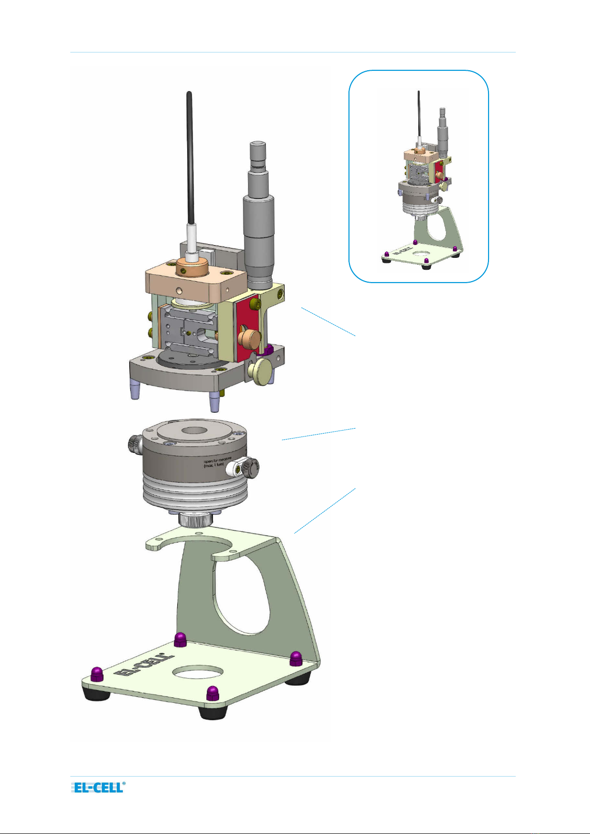
Basic structure of the ECD-3-nano:
Sensor unit
Details shown on the following page
Cell body
Bracket

Page 7 of 46
User Manual ECD-3-nano
Release 1.52
Cut drawing of the ECD-3-nano:
Sensor cable
Micrometer screw
Sensor plunger
Excenter
Locking screw
Spacer disc
Glass T-Frit
Shut-off valve
Capacitive sensor
Flexure
Load
Sensor Tip
Reference electrode
Piston

Page 8 of 46
User Manual ECD-3-nano
Release 1.52
2 Features
The ECD-3-nano is an electrochemical dilatometer for measuring changes of thickness of the
working electrode of a battery test cell. The main features of the ECD-3-nano are briefly
described in the following:
High resolution capacitive sensor system with <5 nm resolution, drift stability of <20
nm/hour (sample-free instrument at constant temperature), and 250 µm full range.
Conditioning electronics with analog output signals (-10 to 10 V) for displacement and
temperature.
Integrated USB data logger for the recording of displacement, temperature, cell potentials
and current.
3-electrode electrochemical cell
3 Technical Data
Working (upper) electrode: bound electrode film or single crystal/grain; max. sample size
10 mm x 1 mm (diameter x thickness)
Counter (lower) electrode: 12 mm diameter
Load on working electrode: 1 N
Electrolyte volume: approx. 0.5 ml
Materials in contact with electrolyte: PEEK, borosilicate glass, stainless steel 316L for
aproti, gold for aqueous electrolytes
Operating temperature range: Cell and sensor: -20 to +70 °C;
Conditioning electronics and data logger: 0 to +40 °C
All measurements in mm
Page 9 of 46
User Manual ECD-3-nano
Release 1.52
4 Safety Precautions
Use proper safety precautions when using hazardous electrolytes. Wear protective glasses and
gloves to protect you against electrolyte that may accidentally spill out of the instrument
during filling, operation, and disassembly.
5Unpacking
Check the contents of the packages against the list given below to verify that you have
received all of the required components. Contact EL-CELL, if anything is missing or damaged.
NOTE: Damaged shipments must remain within the original packaging for freight company
inspection.
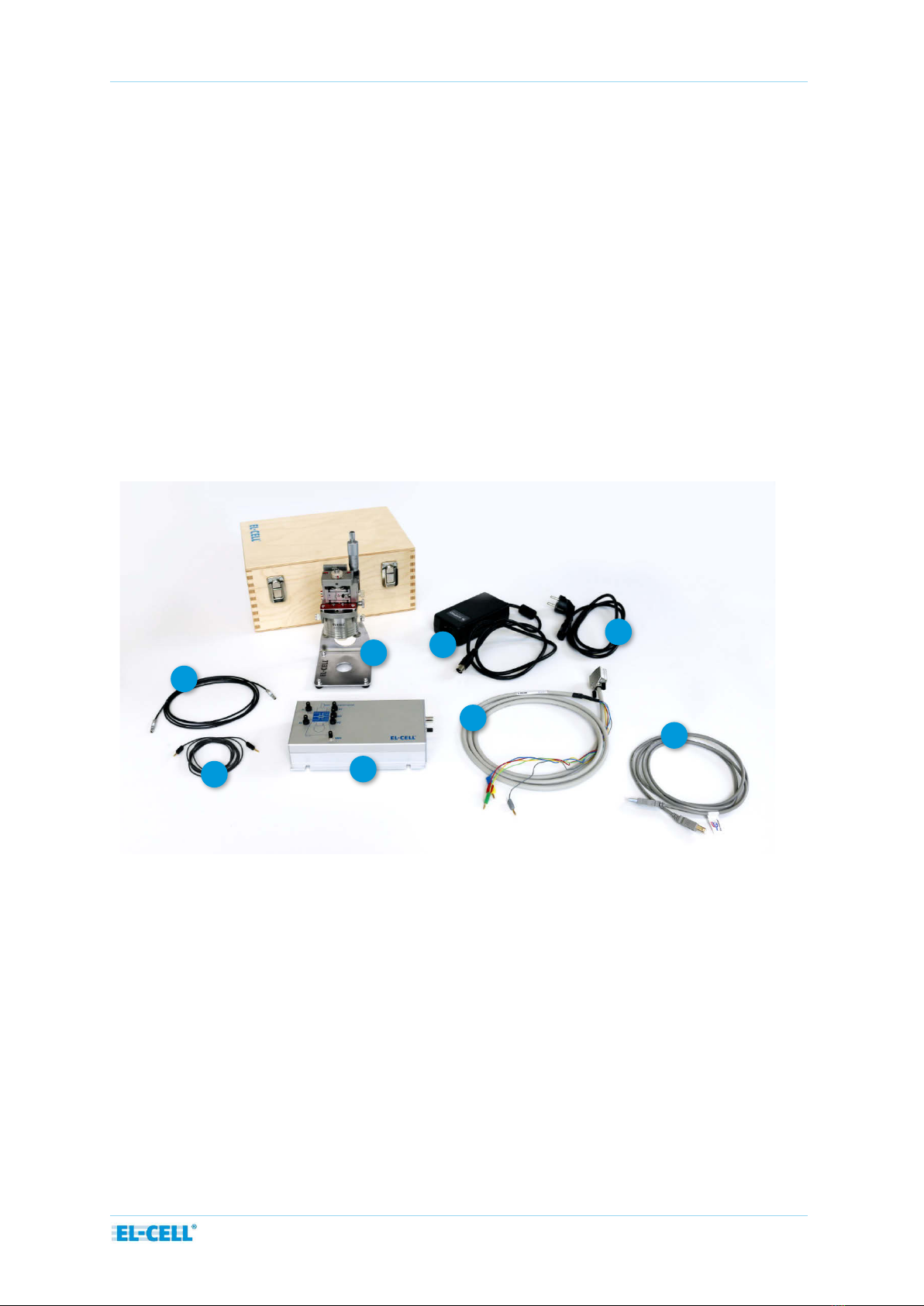
List of Components:
1. ECD-3-nano dilatometer ECD3-00-0001-A, assembled
2. Box ECD-3-nano ECE1-00-0006-F, assembled
3. Sensor-GND cable ECE1-00-0041-A
4. Sensor cable (PISeca) SEN9023
5. ECD cell cable ECE1-00-0033-F
6. Power supply SPU 45E-303 ELT9207
7. Power cord IEC 60320 C14 EURO L sw 1.5 m ELT9222
8. USB cable typ A/B (2.0 m) ELT9167
4
3
2
1
6
5
8
7
Page 10 of 46
User Manual ECD-3-nano
Release 1.52
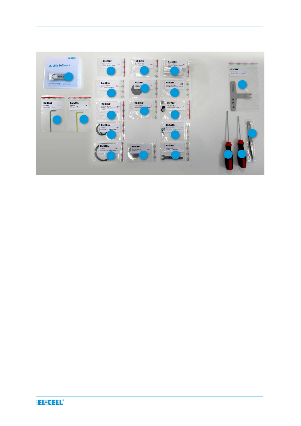
9. USB stick containing EC-Link data logger software ECE1-00-0052-B
10. Allen wrench 2.5 mm WZG9059
11. Allen wrench 3 mm WZG9058
12. 3 x PE Seal II ECD-3 piston ECC1-01-0044-D
13. 3 x PTFE Seal ECD-3 piston ECC1-00-0044-C
14. 1 x PTFE Seal ECD 33.3 x 1.8 mm (3 pcs.) ECC1-01-0043-D/3
15. 3 x O-Ring 33 mm x 1.78 mm DIC9034
16. 3 x O-Ring 50.5 mm x 1.78 mm DIC9038
17. T-Frit 10/12.5 ECC1-00-0041-B
18. Stiff Plate ECD1-00-0041-A
19. 3 x Ferrule 1.5 mm (short top part) ECC1-00-0029-H
20. Membrane (aprotic) 1.4404 ECC1-00-0019-D
21. Spacer disc Set 2.1 – 2.3 mm (3 pcs) ECC1-01-0012-F
22. Separator (GF/A) 12 mm x 0.26 mm (10 pcs) ECC1-01-0012-Q/X
9
18
21
10
19
15
16
17
11
12
13
14
22
23
24
25
26
27
28
29
20

Page 11 of 46
User Manual ECD-3-nano
Release 1.52
23. Demonstration kit for ECD ECD1-00-0900-A
24. Allen wrench set (0.9 / 1.3 / 1.5 / 2) (4 pcs) ECC1-01-0028-A
25. Open end wrench AF7 ECC1-09-2037-A
26. Removing tool for ECD-3 piston ECC1-09-2005-A
27. Allen screw driver 2.5 mm WZG9003
28. Spherical allen screw driver 3 mm WZG9002
29. Tweezer antiacid / stainless WZG9001
8
Page 12 of 46
User Manual ECD-3-nano
Release 1.52
6Start-up and disassembly
Follow the same procedure beginning at step 3 when disassembling the instrument after an
experiment has been completed.
General advise: Practice the assembly procedure outside the glove box with dummy
components before going for the real experiment. Make sure you have understood the how
and why of each single step. Ask us otherwise.
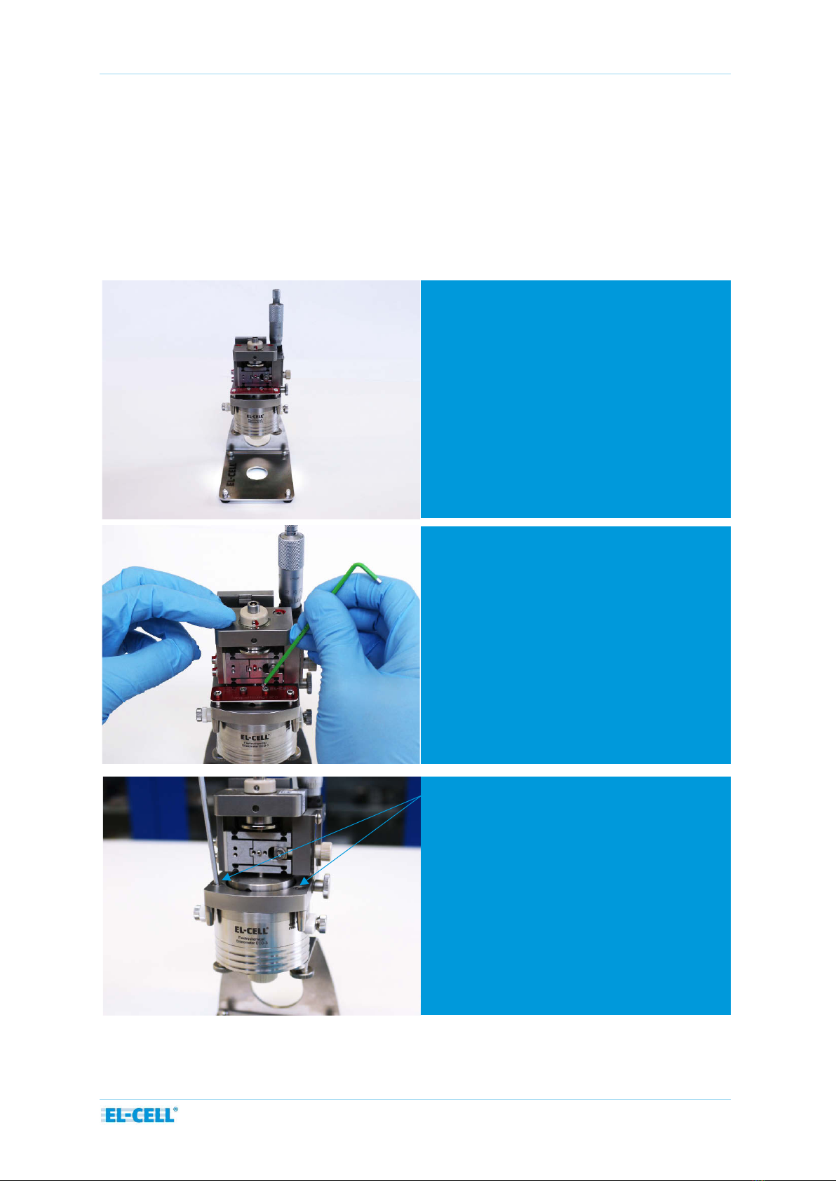
6.1After unpacking the ECD-3, remove the
transport lock from the sensor unit.
6.3Unscrew and detach the sensor unit.
6.2Unscrew the two inner screws first,
only then the two outer screws.

Page 13 of 46
User Manual ECD-3-nano
Release 1.52
6.4Screw off the cell body from the
bracket.
6.5 Unscrew the spring load from the cell
body.
6.6Unscrew the reference electrode.
6.7Remove the cover flange

Page 14 of 46
User Manual ECD-3-nano
Release 1.52
6.8When dissassembling the dilatometer for
the first time, remove the stiff plate below the
cover flange. This plate is for transport only.
For the actual experiment, replace the plate by
the provided metal membrane.
6.10 Now the frit flange with the PTFE-
Seal and the piston in the middle are
visible.
6.9Remove the stiff plate or membrane
from the cell body
6.11 Pull the frit flange out of the cell body.
Page 15 of 46
User Manual ECD-3-nano
Release 1.52
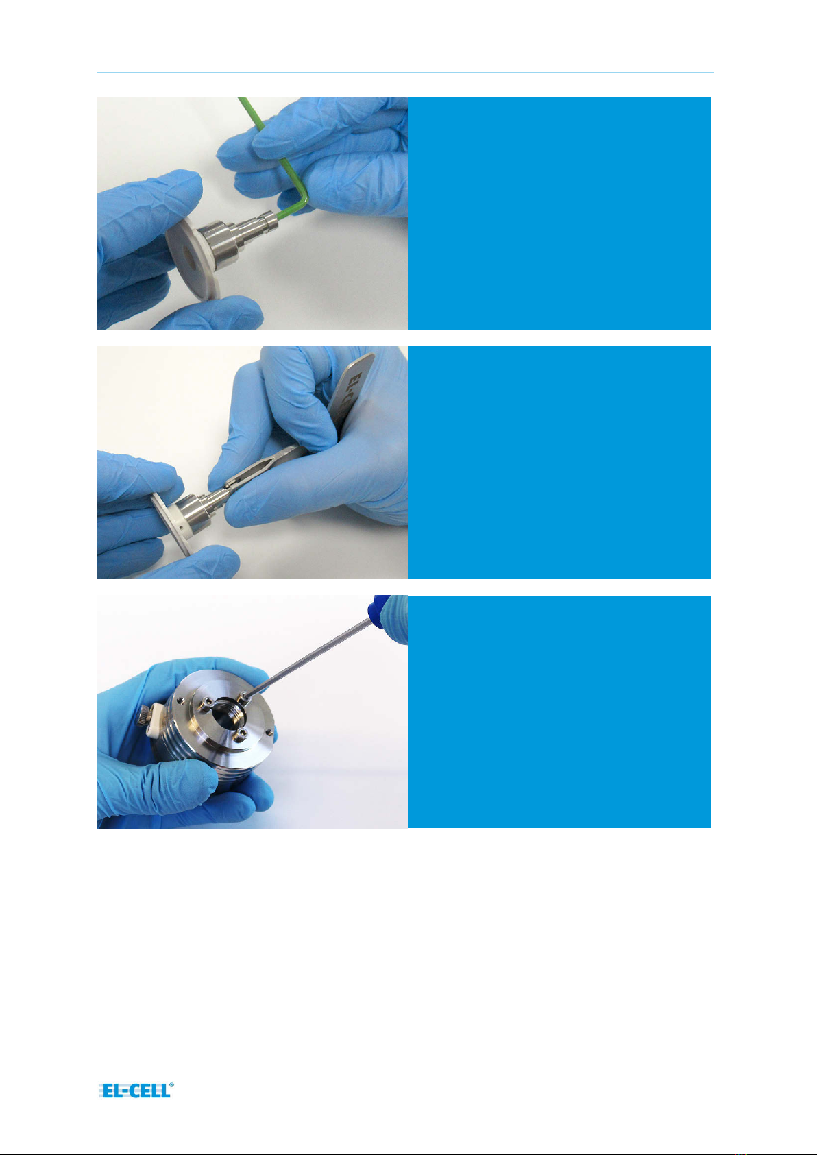
6.12 Loosen the socket screw at the end of
the piston a little with the Allen wrench
(half turn). This releases the disk springs
inside piston and allows it to be pulled
out.
6.13 Pull the piston out of the frit flange
by using the dedicated removal tool.
We advise you to hold the removal tool
between your thumb and index finger as
shown in the picture. This allows the
piston to be pulled out safely.
Remove the T-Frit afterwards.
6.14 Remove the three screws that fix the
dead volume cover.
Page 16 of 46
User Manual ECD-3-nano
Release 1.52
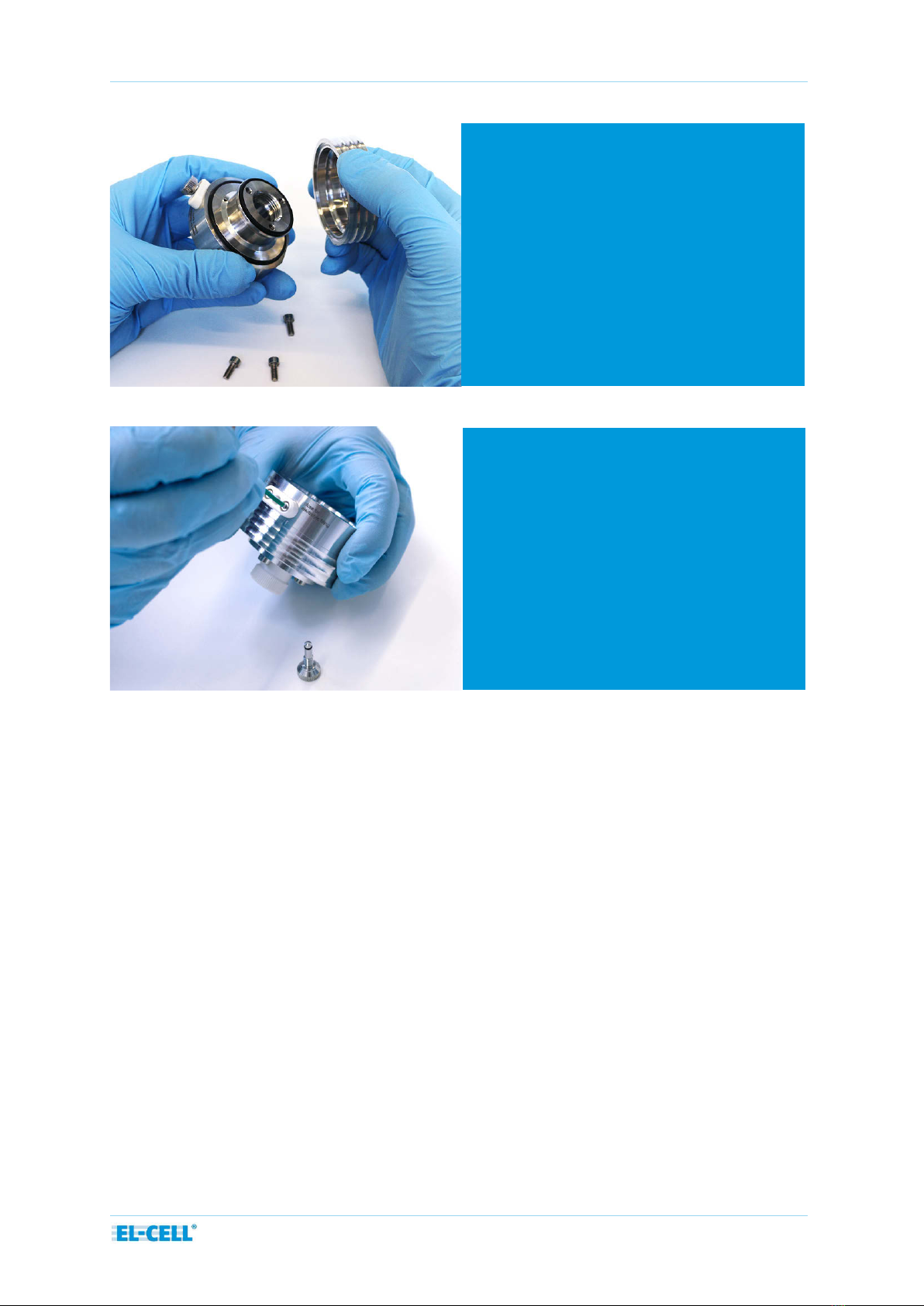
6.15 Remove the dead volume cover and
both O-Rings.
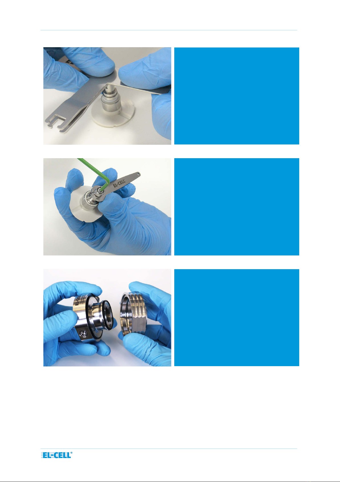
6.16 Unscrew the valve stem and the valve
body.
Page 17 of 46
User Manual ECD-3-nano
Release 1.52
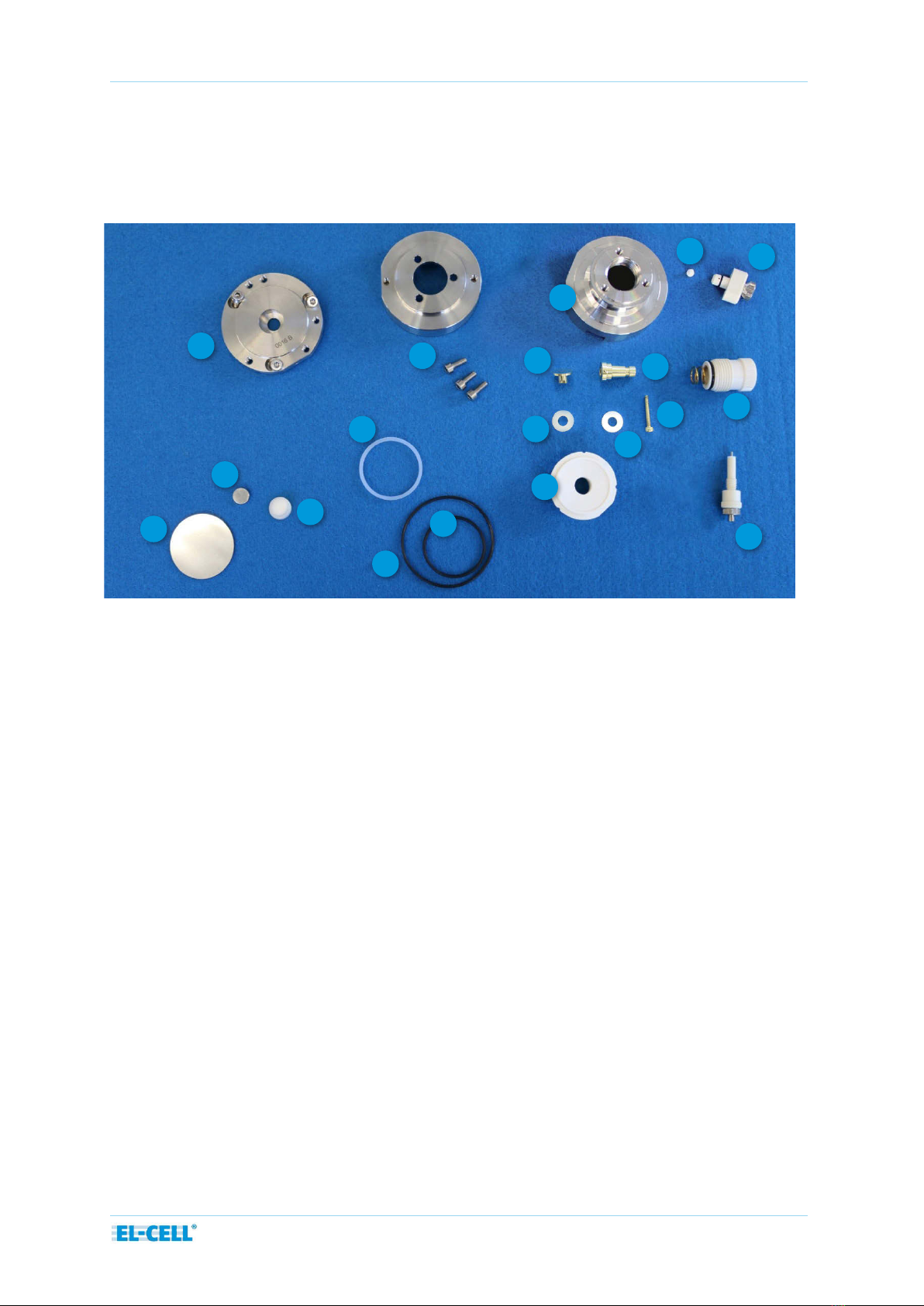
All the below shown parts need to be dried before they can be moved into the glove box for
assembly. Recommended drying conditions: 80°C, <0.01 mbar, 12 hours.
NOTE: For highly moisture sensitive systems, we recommend drying the glass frit separately at
higher temperature: 180°C, <0.01 mbar, 12 hours.
1.Membrane (aprotic) 1.4404
2.Spacer disc (proper thickness depends
on working electrode thickness)
3.T-frit
4.Cover flange with three screws
5.Dead volume cover with three screws
6.ECD-3 base body
7.Frit flange
8.Spring load
9.Reference electrode
10.Piston PTFE-sealing, internal thread
(ECD-3)
11.O-Ring 50.5 x 1.78 mm, EPDM
12.2 x O-Ring 33.05 x 1.78 mm, EPDM
13.Socket screw
14.PE-Seal for ECD-3 (33 mm x 1.6 mm)
15.Ferrule 1.5 mm, PTFE
16.Shut-off valve (Note: This part needs
to be disassembled before drying, see
chapter 13)
17.PTFE Seal ECD-3 piston
18.PE Seal II ECD-3 piston
19.Thrust screw VII (ECD-3)
1
15
6
8
19
4 5
14
7
2
16
3
9
1
12
11
10
13
17
18

Page 18 of 46
User Manual ECD-3-nano
Release 1.52
7Assembling the cell inside the glove box
After moving the different parts of the disassembled cell body into the glove box, follow the
steps below. Protect yourself and handle the chemicals with care.
7.1 Inside the glove box: Insert the T-frit
with the smaller side pointing downwards
into the frit flange.
Note: Make sure that the inside of the frit
flange does not get damaged/ scratched
when inserting the T-frit. Replace the frit
flange as necessary.
7.2 Inside the glove box: Put a glass fiber
separator (12 mm diameter) on top of the
frit
7.3 Inside the glove box: Insert the
lithium metal counter electrode.

Page 19 of 46
User Manual ECD-3-nano
Release 1.52
7.4 Inside the glove box: First place the
PE sealing (PE Seal II ECD-3 piston)
followed by the PTFE sealing (17.PTFE Seal
ECD-3 piston) on the piston. The outward
curved side of the sealing rings must face
away from the piston (see sketch below)
7.5.Inside the glove box: Add the thrust
screw.
Align it so that the mark on the thrust
screw is centered on the recess in the
piston.
7.6 Inside the glove box: Tighten the
socket screw firmly with the provided allen
wrench.
Page 20 of 46
User Manual ECD-3-nano
Release 1.52
7.7 Inside the glove box:Attach the
counter piston from below. Use the
removal tool to push it. Make sure that the
stack is firmly held together.
7.8 Inside the glove box:Tighten the
socket screw at the end of the pistol using
the tools provided.
Important note:
Only use a frit flange with an attached
metal support ring as shown in the
picture. Otherwise the frit flange may
be damaged when trying to tighten the
screw!
7.9 Inside the glove box:Insert the two
big O-rings and attach the dead volume
cover to the base body.
Table of contents
Other EL-CELL Industrial Equipment manuals


Popular Industrial Equipment manuals by other brands

Fireye
Fireye SureFire II SP-48-NG-FD instruction manual

Parker
Parker OLAER IBV Series Repair instructions

Swagelok
Swagelok FTF 1000 user manual

FlexiForce
FlexiForce Frequenz 400-100 instruction manual

Argus
Argus ALPHA OUTBACK ENERGY Cordex 48-1kW instruction manual

Masterbuilt
Masterbuilt HITCH-HAUL HDMF Operation manual & safety instructions


