7
Initiating a charging cycle:
1. Connect the adapter cable to the charging station.
2. Turn a CP switch to B position and wait 3 to 5 seconds – in commercial
stations this may initiate a station to ask for payment information
3. Turn a CP switch to either C or D position depending on the type of
station you are testing (respectively with or without indoor charging
area ventilation requirement) to open the charging cycle.
Note
If the station does not begin the charging cycle, turn the CP switch
to position A. Then turn the CP switch to position B and wait 3 to
5 seconds. Then turn the CP switch to position C or D. Some EV
charging stations require a time delay to establish a proper connection
when CP State B is selected.
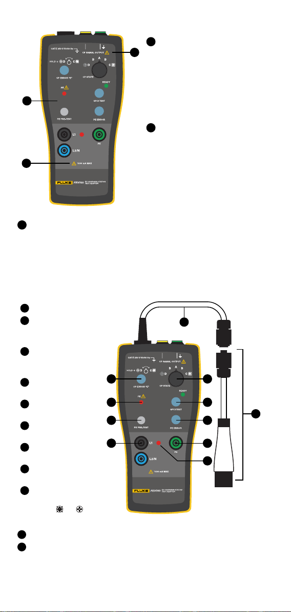
The red LED indicates that the charging station opened for the charging cycle
and voltage is present at the adapter terminals. The green READY indicator
should light up to indicate that the GFCI test circuit is ready for testing.
Measuring terminals of the adapter are directly connected to Phase 1 (L1),
Phase 2 (L2/N) or N (L2/N), and PE conductors of the charging station via
the test cable. Use these terminals for measuring purposes only. Do not use
the terminals to supply power to any other equipment.
Connect a meter to the L1 and L2/N terminals to perform output voltage
measurement. The terminals can be also used to perform other tests (for
example the loop impedance or Power Quality).
Verication of the charging station’s preset maximum charging current
and CP signal
The purpose of the CP function is communication between a vehicle and
charging station. The duty cycle of the PWM Pulse Width Modulation signal
denes the maximum available charging current.
CP output terminals are connected to CP and Ground conductors of the
charging station under test via the test cable. The green socket is connected to
Ground. These outputs are for connection of a meter with a duty cycle function
or an oscilloscope to check the waveform and amplitude of the CP signal.
For details of communication protocol refer to SAE J1772 and the
documentation of the manufacturer of the charging station.
Verication of the maximum charging current with a multimeter
Set a maximum charging current of the charging station using the internal
switch. The value of the maximum charging station current cannot exceed
the max current allowed by the gauge of the installed electrical wires and
breaker according to the National Electrical Code.
Testing maximum charging current:
1. Connect adapter to the charging station and select either state C or
D using rotary switch depending on the type of station to start the
charging cycle.
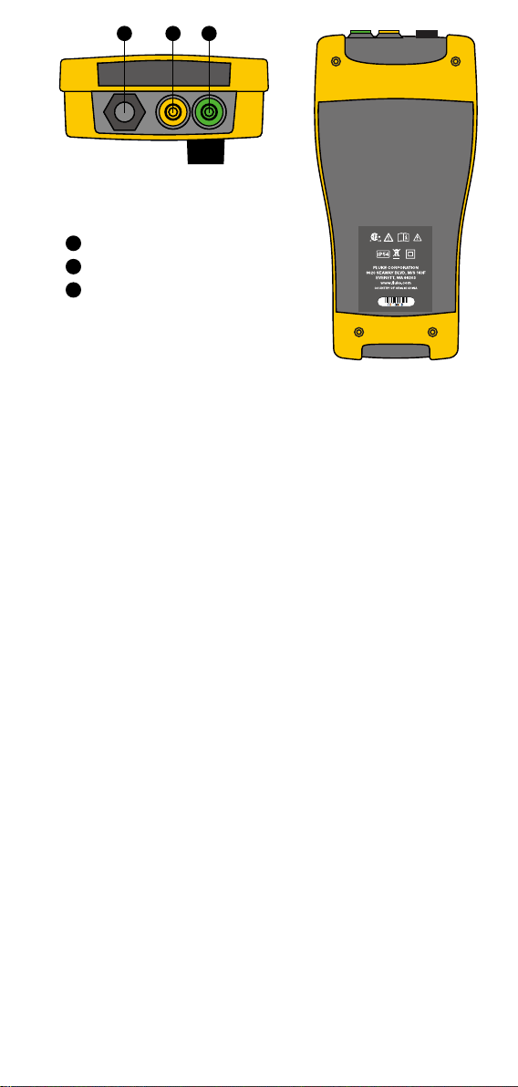
2. Connect meter set to Duty Cycle to the Control Pilot (CP) terminals
located on the top of the adapter. See Figure 3, use items 2and 3.
Make sure to connect COM input of the meter to the Green (Ground)
output of the CP terminal.
3. Read the duty cycle value and translate to maximum charging
current using the below formulas or a quick reference table (based on
J1772 standard).
Note
• Do not connect to L1, L2/N terminals.
• Connect the multimeter test leads after the charging station starts the
charging cycle. In some situations, the meter can inuence the CP
signal, and prevent the station from starting the charging cycle.