Advanced IR Filtering Technology
The IRS1 features Advanced IR Filtering Technology that reduces IRI,
CFL, EMI, and ESI noise sources in addition to blocking plasma TV
emissions. This means that the IRS1 can be used in areas that receive
substantial ambient noise such as near plasma TVs or compact floures-
cent lights.
Note: The IRS1 will take a few seconds to adjust to a given noise
source. During this time, the blue Activity LED will glow brightly
and then fade out. If the interference disappears momentarily,
then returns, the fade down process will repeat. Certain noise
sources, however, (such as plasma screens) may result in low-level
flickering even after the fade down. This is normal. Such signals
have been filtered, allowing most equipment to be controlled.
Extreme Ambient Noise
In situations where the IRS1’s advanced IR filtering does NOT success-
fully filter ambient noise (in very close proximity to a plasma TV, for
example), an ELAN IRS7EP or IRS8EP Extreme Plasma IR Sensor should
be used. Please see the IRS7EP and/or IRS8EP Instructions for addi-
tional information.
IRS1
Miniature
Surface-Mount
IR Sensor w/Plug
Limited Warranty
ELAN HOME SYSTEMS, L.L.C (ELAN) warrants this product to be free from defects in materials
and workmanship for five (5) years from date of purchase. If within the warranty period purchaser
discovers such item was not as warranted above and promptly notifies ELAN in writing, ELAN
shall repair or replace the items at the company’s option. This warranty shall not apply (a) to
equipment not manufactured by ELAN, (b) to equipment which shall have been installed by other
than an authorized ELAN installer, (c) to installed equipment which is not installed to ELAN’s spec-
ifications, (d) to equipment which shall have been repaired or altered by others than ELAN, (e) to
equipment which shall have been subjected to negligence, accident, or damage by circumstances
beyond ELAN’s control, including, but not limited to, lightning, flood, ,electrical surge, tornado,
earthquake, or any other catastrophic events beyond ELAN’s control, or to improper operation,
maintenance or storage, or to other than normal use of service. With respect to equipment sold
by, but not manufactured by ELAN, the warranty obligations of ELAN shall in all respects conform
and be limited to the warranty actually extended to ELAN by its supplier. The foregoing war-
ranties do not cover reimbursement for labor, transportation, removal, installation, or other
expenses which may be incurred in connection with repair or replacement.
Except as may be expressly provided and authorized in writing by ELAN, ELAN shall not be sub-
ject to any other obligations or liabilities whatsoever with respect to equipment manufactured by
ELAN or services rendered by ELAN.
THE FORGOING WARRANTIES ARE EXCLUSIVE AND IN LIEU OF ALL OTHER EXPRESSED AND
IMPLIED WARRANTIES EXCEPT WARRANTIES OF TITLE, INCLUDING BUT NOT LIMITED TO
IMPLIED WARRANTIES OF MERCHANTABILITY AND FITNESS FOR A PARTICULAR PURPOSE.
©2005 ELAN Home Systems P/N 224256 X2
Introduction
The IRS1 is a miniature ‘plasma-friendly’ IR sensor designed to be
mounted on flat surfaces: furniture recesses, under shelves, etc. This
sensor uses advanced IR filtering technology which allows it to work
even in areas that receive normally harmful interference (near plasma
TV’s, compact flourescent lights, etc.). The IRS1 features a 3.5mm Quad
plug for easy connection to IR distribution blocks, multi-room con-
trollers, etc. The IRS2 Miniature Surface-Mount IR Sensor w/ Bare
Leads is also available if the Quad Plug is not required.
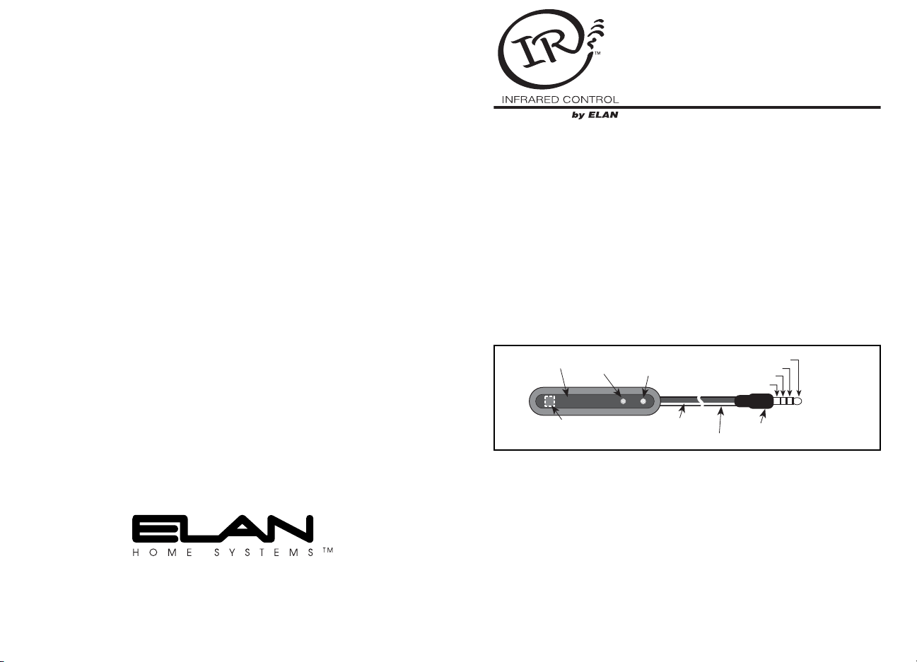
Features
• 3.5mm Quad Plug Accommodates STATUS, IR, +12VDC, & GND
• ‘Plasma-Friendly’ Technology Helps Block Plasma TV Interference
• IR Lens Rejects Visible Light Interference
• Internal Crosshatch Shield Inhibits EMI/ESI Interference
• STATUS Indicator: Green LED for System On/Off Indication
• ACTIVITY Indicator: Blue LED Indicates IR Signal Activity
Specifications:
• Requires 12VDC power supply, termination block and IR emitters for
IR operation.
• Mounting: Attach to any flat surface using included adhesive strip.
Apply adhesive strip to the back, top, or bottom surfaces of the IRS1.
• Power: +12VDC @ 6mA
• Carrier Frequency Acceptance Range: 28kHz to 90kHz
• Control Range: Up to 35 feet, depending on remote strength and
ambient noise conditions.
• Control Angle: +/- 50 degrees off-axis
• Room-to-Room Wire Recommendations: Cat-5
• Maximum recommended cable length: 1200 feet using Cat-5
• Dimensions: 2 9/16" (65mm) L x 9/16"(14mm) W x 1/2" (13mm) D