Elan D12 User manual


ELAN HOME SYSTEMS
© ELAN Home Systems 2009 • All rights reserved. Page I
D12 INSTALLATION MANUAL
Preface
Purpose of This Manual
This manual provides step-by-step installation instructions and connection examples, along with basic user
information for installation and ongoing use of the D12 Digital Power Amplifier. This manual is written for the
installer of this equipment.
Organization
The following information is contained in this manual:
Safety Information Provides a comprehensive list of safety practices and procedures allowing for
the safe installation and operation of ELAN Home Systems’ D12 Digital Power
Amplifier.
D12 Introduction Provides an introduction to the D12 Digital Power Amplifier, along with system fea-
tures to include Front and Rear panel controls, indicators and connections, along
with a short description of each.
D12 System Design
Overview
Provides a system design application overview of the D12 Digital Power Amplifier for
use in audio applications.
D12 Connections Provides a description of D12 Digital Power Amplifier connections including
connections made with ELAN Multi-Room Systems and direct connections to the
the D12 Digital Power Amplifier from other components.
Troubleshooting Provides troubleshooting tables to help fix common discrepancies that may
be associated with the D12 Digital Power Amplifier.
Specifications Appendix A provides equipment specifications for the D12 Digital Power Amplifier.
Rack Mounting Appendix B provides specifications for Rack Mounting of the D12 Digital Power
Amplifier using the included Rack Mount Brackets.

ELAN HOME SYSTEMS
Page II © ELAN Home Systems 2009 • All rights reserved.
D12 INSTALLATION MANUAL
RISK OF ELECTRIC SHOCK
DO NOT OPEN!
WARNING
CAUTION: TO REDUCE THE RISK OF ELECTRIC SHOCK, DO NOT
REMOVE COVER (OR BACK). NO USER SERVICEABLE PARTS INSIDE.
REFER SERVICING TO QUALIFIED SERVICE PERSONNEL.
WARNING: TO REDUCE THE RISK OF FIRE OR SHOCK,
DO NOT EXPOSE THIS APPLIANCE TO RAIN OR MOISTURE.
The lightning flash with arrowhead symbol within an equilateral triangle is intended to
alert the user to the presence of uninsulated "dangerous voltage" within the product's
enclosure that may be of sufficient magnitude to constitute a risk of electric shock to persons.
The exclamation point within an equilateral triangle is intended to alert the user to the presence
of important operating and maintenance (servicing) instruction in the literature accompanying
the appliance.
CAUTION
CAUTION: RISK OF EXPLOSION IF BATTERY IS REPLACED BY AN
INCORRECT TYPE. DISPOSE OF USED BATTERIES ACCORDING TO
THE INSTRUCTIONS.
IMPORTANT SAFETY INFORMATIONIMPORTANT SAFETY INFORMATION
Read Information—All the safety and operating information should be read before the appliance is operated.
Follow Information—All operating and use information should be followed.
Retain Information—The safety and operating information should be retained for future reference.
Heed Warnings—All warnings on the appliance and in the operating instructions should be heeded.
Wall Mounting—Mounting of this appliance should be done only by an authorized installer.
Ventilation—The appliances should be situated so that their location or position does not interfere with their proper ventilation.
These appliances should never be placed near or over a radiator or heat register.
These appliances should not be placed in a built-in installation such as a bookcase or cabinet that may impede the flow of air through the ventila-
tion openings.
Non-Use Periods—Appliances that are left unattended and unused for long periods of time should be de-energized.
Power Sources—The appliances should be connected to a power supply only of the type described in the operating instructions or as
marked on each appliance. If you are not sure of the type of power supply to your home, consult your authorized ELAN dealer or local power
company.
Grounding or Polarization—Do not defeat the safety purpose of the polarized or grounding-type plug. A polarized plug has two
blades with one blade wider than the other blade. A grounding type plug has two blades and a third grounding prong. The polarized wide blade
and the third prong are provided for your safety. If the provided plug does not fit your outlet, consult an electrician for replacement of the obsolete
outlet.

ELAN HOME SYSTEMS
© ELAN Home Systems 2009 • All rights reserved. Page III
D12 INSTALLATION MANUAL
Water and Moisture—To reduce the risk of electric shock or fire, these appliances should not be used near water ––for example, near
a bathtub, washbowl, kitchen sink, laundry tub, in a wet basement, or near a swimming pool.
Power Cord Protection—Protect the power cord from being walked on or pinched particularly at plugs, convenience receptacles and
the point where they exit from the apparatus.
Telephones—Avoid using a telephone (other than a cordless type) during an electrical storm. There may be a remote risk of electrical shock
from lightning. Do not use a telephone to report a gas leak if the leak is in the vicinity of the ELAN electronic equipment because of risk of fire or
explosion.
Cleaning—Unplug the apparatus from the power outlet before cleaning. Use only a dry cloth to clean the apparatus.
Power Lines—An outdoor antenna should be located away from power lines. When installing an outside antenna system, extreme care
should be taken to avoid touching power lines or circuits, as contact with them may be fatal.
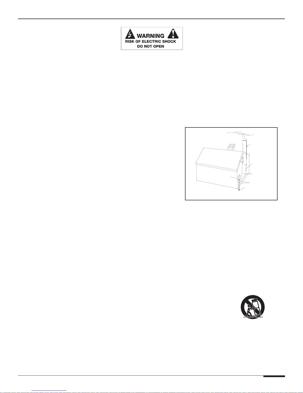
Outdoor Antenna Grounding—If an outside antenna or cable system
is connected to these audio products, be sure the antenna or cable system is grounded
so as to provide some protection against voltage surges and built-up static charges-
Section 810 of the U.S. National Electrical Code, and Section 54 of the
Canadian Electrical Code, provide information with respect to proper grounding of
the mast and supporting structure, grounding of the lead-in wire to an antenna
discharge unit, size of grounding conductors, location of antenna-discharge unit,
connection to grounding electrodes, and requirements for the grounding electrode.
See the grounding diagram (right).
Overloading—Do not overload wall outlets and extension cords, as this could
result in fire or electric shock.
Object and Liquid Entry—Never insert objects of any kind through the
openings of these appliances, as they may touch dangerous voltage points or
short-out parts that could result in a fire or electric shock. Care should be taken so that
objects do not fall and liquids are not spilled into the appliance through openings in the enclosure.
Servicing—Do not attempt to service these appliances yourself, as opening or removing covers may expose you to dangerous voltage or
other hazards. Refer all servicing to qualified service personnel.
Damage Requiring Service—These appliances should be serviced by qualified service personnel when:
• A power supply connection or a plug has been damaged or
• If liquid has been spilled into the appliance or objects have fallen into the appliance or
• The appliance has been exposed to water or moisture or
• The appliance does not appear to operate normally or exhibits a marked change in performance or
• The appliance has been dropped or the enclosure damaged.
Replacement Parts—When replacement parts are required, be sure the service technician has used replacement parts specified by
the manufacturer or that have the same characteristics as the original part. Unauthorized substitutions may result in fire, electric shock, or other
hazards. The Master Control Unit battery should be replaced only after turning the power off and only by an authorized installer.
Safety Check—Upon completion of any service or repairs to this audio product, ask the service technician to perform safety checks to
determine that the audio product is in proper operating condition.
Lightning Storms—Unplug this apparatus during lightning storms or when unused for long periods of time.
Attachments and Accessories—Use only attachments/accessories specified by the manufacturer.
Cart, Stand, Tripod, Bracket or Table—Use only with a cart, stand, tripod, bracket or table specified by the manufacturer, or
sold with the apparatus. When a cart is used, use caution when moving the cart/apparatus combination to avoid injury from tip over.
Disconnect Device—Where the mains plug or an appliance coupler is used as the disconnect device, the disconnect device shall
remain operable.
ELECTRIC
SERVICE
EQUIPMENT
GROUND
CLAMPS
POWER SERVICE GROUNDING
ELECTRODE SYSTEM
(CEC SECTION 10-700)
ANTENNA
LEAD-IN WIRE
GROUND CLAMPS
GROUNDING CONDUCTORS
(CEC SECTION 54-200)
ANTENNA LEAD-IN WIRE
(CEC SECTION 54-200)
NEC - NATIONAL ELECTRICAL CODE
(NEC SECTION 810-20)
(NEC SECTION 810-21)
(NEC ARTICLE 250, PART H)
CEC - CANADIAN ELECTRICAL CODE
Grounding
Diagram

ELAN HOME SYSTEMS
Page IV © ELAN Home Systems 2009 • All rights reserved.
D12 INSTALLATION MANUAL
Table of Contents
Preface �������������������������������������������������������������������������������������������������������������������������������� I
Introduction �����������������������������������������������������������������������������������������������������������������������VII
D12 Features ��������������������������������������������������������������������������������������������������������������������� VII
Identification of Controls���������������������������������������������������������������������������������������������������� 1
Rack Mounting ������������������������������������������������������������������������������������������������������������������� 3
Operations & Settings��������������������������������������������������������������������������������������������������������� 4
Front Panel Controls ...........................................................................................................................................4
Channel Button ........................................................................................................................................4
Menu Button .............................................................................................................................................4
UP & DOWN Arrow Buttons ................................................................................................................5
Menu Options .......................................................................................................................................................5
Normal Mode ........................................................................................................................................................6
Volume Menu ...........................................................................................................................................6
Setting System Volume Levels ...........................................................................................................7
Input Select Menu ..................................................................................................................................8
Channel Lock Menu .............................................................................................................................10
ACE Menu ...............................................................................................................................................10
Power Saving Menu .............................................................................................................................11
Output View Menu ................................................................................................................................12
Utility Menu ..........................................................................................................................................................12
Operating Mode ....................................................................................................................................13
LCD Contrast .........................................................................................................................................13
LCD Brightness .....................................................................................................................................14
LCD Sleep Timer ...................................................................................................................................14
Power Saving Mode .............................................................................................................................15
Firmware Version ..................................................................................................................................17
Diagnostics Menu .................................................................................................................................17
Ambient Temperature ..........................................................................................................................18
Save Dealer Defaults ...........................................................................................................................18
Restore Defaults ....................................................................................................................................20
ELAN Mode .........................................................................................................................................................21
Absolute Max Volume Menu ..............................................................................................................21
Minimum Turn-On Volume Menu .....................................................................................................22

ELAN HOME SYSTEMS
© ELAN Home Systems 2009 • All rights reserved. Page V
D12 INSTALLATION MANUAL
Maximum Turn-On Volume Menu ....................................................................................................22
VIA!NET Address ...................................................................................................................................23
Channel Range ......................................................................................................................................23
Fault Menu (For both Normal and ELAN Modes) ........................................................................24
Connections����������������������������������������������������������������������������������������������������������������������� 25
Line Level Audio Inputs ....................................................................................................................................25
BUS Inputs...........................................................................................................................................................26
BUS Outputs .......................................................................................................................................................26
Speaker Binding Post .......................................................................................................................................27
Triggers .................................................................................................................................................................28
IR LOOP INPUT/OUTPUT Connections .....................................................................................................30
VIA!NET LOOP INPUT/OUTPUT Connections ..........................................................................................31
USB Connector ..................................................................................................................................................32
AC Power Connector ........................................................................................................................................32
Applications����������������������������������������������������������������������������������������������������������������������� 33
Stereo Input with Stereo Output ...................................................................................................................33
Multiple Stereo Inputs .........................................................................................................................35
Single Stereo Input with Stereo and Mono Output ....................................................................36
Single Stereo Input with Stereo out on Channels 1 - 8 .............................................................38
Stand-Alone Stereo Bussing with Multiple Chassis ...................................................................41
Multi-Room Stereo Zones ..................................................................................................................43
S128P Sub-Zones ................................................................................................................................44
Troubleshooting ����������������������������������������������������������������������������������������������������������������� 47
Specifications �������������������������������������������������������������������������������������������������������������������� 50

ELAN HOME SYSTEMS
Page VI © ELAN Home Systems 2009 • All rights reserved.
D12 INSTALLATION MANUAL
Items in package:
• D12PowerAmplifier
• RackMountBrackets
• PowerCord
• InstallationManual

ELAN HOME SYSTEMS
© ELAN Home Systems 2009 • All rights reserved. Page VII
D12 INSTALLATION MANUAL
Introduction
Introducing the latest in ELAN digital amplifier design and innovation - the D12 Digital Power Amplifier. Designed
specifically for the custom installer, the D12 is the perfect solution for multi-room whole-house applications.
Providing cool performance and flexibility, the D12 delivers 12 channels of powerful audio that can be configured
into many combinations to suit any situation that may be encountered in a whole-house distributed audio system.
The D12 utilizes low heat/high efficiency Class D digital technology which features an 8X over-sampling rate and
48-bit signal processing delivering the cleanest and most efficient audio amplification available. Each channel of
the D12 has a true power rating of 75W per channel @ 8 Ohms and 100W per channel @ 4 Ohms - all channels
driven.
Configuration of the D12 can be done via front panel interface including Advanced setup features such as max
volume output, min/max turn on levels. Independent Channel IR commands are available in ELAN's configuration
software.
D12 Features
Class D Digital Technology
• Constructed with the highest quality components including Pro-Sound analog to digital (A/D) converters,
superior grade capacitors, and high quality 5-way speaker binding terminals, the end result is a sound that
is clean, clear and transparent.
75WPC @ 8 Ohms & 100WPC @ 4 Ohms
• The D12 combines micro controller technology to maximize efficiency and a muscular Multi-Tap Toroid power
transformer to provide all the power necessary to ensure the delivery of deep powerful bass, musical mids
and sparkling highs to any whole-house application.
Automatic Clipping Eliminator
• The D12 Limiter enables the amplified output to be continuously monitored for signal clipping.
Intelligent Monitoring
• The D12 utilizes advanced micro controller operational circuity that constantly monitors all of the amplifier's
operation modes. Channel fault, thermal and impedance load monitoring for each channel provides important diag-
nostical information. In the event that a problem occurs on a channel during operation, the other channels will con-
tinue to provide audio. When the conditions for the troubled channel no longer exist, regular operation will resume
after a front panel reset is performed.
Multiple Input and Bus Options
• The D12 has two stereo Bus inputs that are available to any or all 12 channels. Any stereo pair, including the
bus inputs, can be summed internally for a mono channel output. These advanced routing features are program-
mable setup features through the front panel LCD. The front panel display also provides status monitoring and
diagnostics.

ELAN HOME SYSTEMS
Page VIII © ELAN Home Systems 2009 • All rights reserved.
D12 INSTALLATION MANUAL
Buffered Loop Outputs
• Flexible routing of each audio channel without signal loss.
IR Control Files
• Independent channel Volume Up, Volume Down, Input Selection, Power, Mute, Link/Unlink channel pairs and
more.
USB Port
• For firmware and configuration updates.
VIA!Net jack
• For control and monitoring.
Rack-Mount Brackets Included
• Easily mount in a standard equipment rack.
Available in 240 Volt Version
cTUVus Certified, CE®, and C-tick

ELAN HOME SYSTEMS
© ELAN Home Systems 2009 • All rights reserved. Page IX
D12 INSTALLATION MANUAL
This D12 Digital Power Amplifier is capable of delivering in excess of 75 Watts into 8 Ohm loads and in excess of
100 Watts into 4 Ohm loads.
All devices connected to the D12, including but not limited to speakers, volume controls, speaker selectors, etc.,
should have a minimum power handling specification of 75 Watts @ 8 Ohms and 100 Watts @ 4 Ohms.
Failure to use properly rated devices can result in damage to the connected device, the amplifier, and may present a
fire hazard.
CAUTION


ELAN HOME SYSTEMS
© ELAN Home Systems 2009 • All rights reserved. Page 1
D12 INSTALLATION MANUAL
Identification of Controls
Front Panel
1
2
3
4
5
6
IR
Front Panel Functions & Indicators
Item Description
1
Channel Selector
2
Menu
3
Up Selector
4
Power LED
5
Down Selector
6
IR Icon Display
Front Panel Functions & Indicators

ELAN HOME SYSTEMS
Page 2 © ELAN Home Systems 2009 • All rights reserved.
D12 INSTALLATION MANUAL
Rear Panel
1 2 4 5
3
78
96
10
1112
}
13
O
I
BUS
B
+
8
_
+8
7
OUT
OUTIN
6
5
IN
12
11
OUT
IN
IN
9
10
VIA!NET
IR
7/8
5/6
+12VDC
TRIGGER
OUT
SPREAKER OUTPUTS (CLASS 2 WIRING) 75 W/CH @ 8 ohms
IN
OUT
IR
OUTPUT
INPUT
11/12
9/10
3/41/2
ALL
ON
+12V TRIGGER INPUTS
Model D12
Digital Power Amplifier
REPLACE WITH
SAME TYPE AND
RATING ONLY.
BUS
A
IN OUT
4
13
OUTIN
2
+
_
2
+
_
1
+
120V 60 Hz
1440W
POWER
_
7
OUT
OUT
T12.5 AL
+
+
3
+
_
_
109
_
4
+
+
_
_
+
+
+
_
6
+
__
+
12
5
11
USB
Rear Items & Connectors
Item Description
1
Power Switch
2
Channels 1-12 Speaker Outputs, 5 Way Binding Post
3
BUS A RCA Stereo Inputs/Outputs, Channels 1 and 2
BUS B RCA Stereo Inputs/Outputs, Channels 7 and 8
4
RCA Stereo Inputs Channels 1-12
5
RCA Stereo Outputs Channels 1-12
6
+12V Channel Pair Trigger Inputs, Triggers 1-2, 3-4, 5-6, 7-8, 9-10, 11-12
7
+12V All On Trigger Input
8
+12V Trigger Output
9
IR Output
10
IR Input
11
VIA!NET Input/Output
12
USB Mini B Port
13
Power Cable Connector
Rear Items & Connectors

ELAN HOME SYSTEMS
© ELAN Home Systems 2009 • All rights reserved. Page 3
D12 INSTALLATION MANUAL
Rack Mounting
When mounting the D12 in an equipment rack, use the included Rack Mount Brackets for secure mounting and
proper ventilation. The D12 requires three rack spaces.
To install the D12 into a standard 19” equipment rack:
1. Attach the rack mount bracket onto the D12 chassis from the front as shown in Figure C-1.
Figure C-1
2. Ensure that the brackets are flush with the front of the unit. Install each of the eight screws (included) through
the side mounting flanges into the holes in the sides of the unit as shown in Figure C-2. Hand tighten screws!
Over-tightening could cause damage to the D12 Tuner.
Figure C-2
3. Once the brackets are securely mounted, install the entire assembly into a standard 19” equipment rack from the
front using four rack screws (not included). Three rack spaces will be used. See Figure C-3.
19" Equipment Rack
Rack Screws
Rack Screws
Figure C-3

ELAN HOME SYSTEMS
Page 4 © ELAN Home Systems 2009 • All rights reserved.
D12 INSTALLATION MANUAL
Operations & Settings
Front Panel Controls
The D12 front panel buttons provide control for the initial setup and amplifier status. Any button press activates the
front panel LCD and displays the information until the LCD times out.
Front Panel Controls
Channel Button
The Channel button toggles through all available channels as well as the ALL channel option. Once a channel
has been selected, the UP and DOWN buttons control the MENU item. In the UTILITY menu, the Channel button
cycles through the UTILITY sub-menu structure.
Menu Button
The MENU button toggles through all Settings options. The Settings options will be slightly different depending if
you are in Normal Mode or ELAN Mode.

ELAN HOME SYSTEMS
© ELAN Home Systems 2009 • All rights reserved. Page 5
D12 INSTALLATION MANUAL
Normal Mode
Normal Mode menu items are:
Amplifier Status, Volume, Input Select, Lock, Limiter, Power Saving, Output View, and Utility.
The Utility menu items are:
Operating Mode, LCD Contrast, LCD Brightness, LCD Sleep Timer, Power Saving Mode, Firmware
Version, Diagnostics, Ambient Temperature, Save Dealer Defaults, and Restore Defaults.
ELAN Mode
The ELAN mode menu items are the same except for the following additional menu items that are after Output
View:
Absolute Max Volume, Min Turn On Volume, and Max Turn On Volume.
Amplifier Status, Volume, Input Select, Lock, Limiter, Power Saving, Output View, Absolute Max Volume, Min
Turn On Volume, Max Turn On Volume and Utility
The Utility mode menu items are the same except for the following additional menu items that are after Operating
Mode:
VIA!NET Address and Channel Range.
Operating Mode, VIA!NET Address, Channel Range, LCD Contrast, LCD Brightness, LCD Sleep Timer, Power
Saving Mode, Firmware Version, Diagnostics, Ambient Temperature, Save Dealer Defaults, and Restore Defaults.
UP & DOWN Arrow Buttons
Adjusts menu selected item values incrementally.
Menu Options
The D12 Amplifier has two operating modes, Normal and ELAN.
ELAN mode provides feedback through VIA!NET and also allows the amplifier to listen to D12 IR Commands that
can effect its channels.
Normal mode does not listen to IR Commands or allow VIA!NET feedback.

ELAN HOME SYSTEMS
Page 6 © ELAN Home Systems 2009 • All rights reserved.
D12 INSTALLATION MANUAL
Normal Mode
Amplifier Status
When the MENU button is pressed for the first time, at Power ON, or after 50 seconds of no button activity, the
Amplifier Status screen displays.
The top of the screen displays what Mode you are in, either ELAN MODE or NORMAL MODE followed by the
channels of this chassis I.E. CH1 - CH12.
CH1 V50 IN1 means that audio input 1 (IN1) is being amplified at 50% (V50) and being routed to channel 1
(CH1).
Amplifier Status
Press UP or DOWN buttons to cycle channels four at a time.
Press Channel button to cycle one channel at a time.
Press the MENU button to move to the next menu.
Volume Menu
The VOLUME menu will allow any or all channel's volume to be adjusted from 0% (MUTE) to 100% (full gain).
The Factory Default setting for each channel is 75.
The VU (Volume Unit) bar displays real time (current) volume detected at the selected channel output. The range is
from -50 dB to 0 dB.
TRIGGER and PS (Power Sense)
See "Power Saving Menu" on page 11, "Power Saving Mode" on page 15, and "Triggers" on page 28.
Trigger ON is the factory default.
The TRIGGER options are:
• On: The selected channel is on (consuming energy) and the trigger jack on the rear panel is active.
• Off: The selected channel is off (NOT consuming energy) and the trigger jack on the rear panel is not active.
• On/PS: The selected channel is off (NOT consuming energy) because the selected channel is in Power Saving
Mode even though the trigger jack on the rear panel is active.
When ACE is active on the selected channel, ACE will be displayed above Volume %. See "ACE Menu" on
page 10.

ELAN HOME SYSTEMS
© ELAN Home Systems 2009 • All rights reserved. Page 7
D12 INSTALLATION MANUAL
Volume Menu with ACE
When AVR is active, AVR (Automatic Volume Reduction) is displayed above Volume %. AVR is active whenever
the amp is being overdriven. When AVR is active, the D12 turns its volume down until it is not being overdriven.
The D12 will turn its volume up when it is not being overdriven.
Volume Menu with AVR
Press UP or DOWN buttons to change the Volume %.
Press Channel button to change the channel.
Press the MENU button to move to the next menu.
Setting System Volume Levels
1. Set each D12's channel levels by first lowering them to 25%.
2. Raise the volume of all touch panels, touchpads or volume controls to near maximum.
3. Play source program material, such as a CD or a radio station.
4. Have someone step into the room and listen.
5. Enable ACE for all channels. See "ACE Menu" on page 10

ELAN HOME SYSTEMS
Page 8 © ELAN Home Systems 2009 • All rights reserved.
D12 INSTALLATION MANUAL
6. On the Volume screen, select the channel that is wired to the speaker where the person is listening.
7. Slowly adjust Volume Up for this channel until the audio begins to distort, then drop the level one or two per-
centages.
8. Follow this procedure for all channels to achieve a good balance of sound from the most used listening posi-
tion in the zone.
9. Enable or Disable ACE for all applicable channels. See "ACE Menu" on page 10
Note: High volume levels can cause clipping and distortion. This can damage the loudspeaker's components and
cause the amplifier to go into protection mode. The protection circuits will reset when the output signal conditions
have returned to normal. Overdriving the amplifier can damage the amplifier and void the manufacturer's warranty.
Input Select Menu
The INPUT SELECT menu will allow any or all of the D12's channels to be configured among six options:
This example is with Channel 1 selected.
Channel 1 Selected
• Input 1 Direct: This is the default, Channel's audio is taken from audio input 1
• Input 1 + 2 Mono Direct: Channel's audio is the sum of audio input 1 and 2 (Mono)
• Input 1 Bus A: Channel's audio is taken from audio input 1 which is Bus A
• Input 1 + 2 Mono Bus A: Channel's audio is the sum of audio input 1 and 2 (Mono) which is Bus A
• Input 7 Bus B: Channel's audio is taken from audio input 7 which is Bus B
• Input 7 + 8 Mono Bus B: Channel's audio is the sum of audio input 7 and 8 (Mono) which is Bus B
Notice that Input 1 Direct is audio input 1 which is the same as Input 1 Bus A. Also notice that Input 1 + 2
Mono Direct is audio input 1 and 2 summed which is the same as Input 1 + 2 Mono Bus A. This is because
the selected channel is channel 1. To help clarify this, see the next example with channel 5 selected.

ELAN HOME SYSTEMS
© ELAN Home Systems 2009 • All rights reserved. Page 9
D12 INSTALLATION MANUAL
This example is with Channel 5 selected.
Channel 5 Selected
• Input 5 Direct: Default, Channel's audio is taken from audio input 5
• Input 5 + 6 Mono Direct: Channel's audio is the sum of audio input 5 and 6 (Mono)
• Input 1 Bus A: Channel's audio is taken from audio input 1 which is Bus A
• Input 1 + 2 Mono Bus A: Channel's audio is the sum of audio input 1 and 2 (Mono) which is Bus A
• Input 7 Bus B: Channel's audio is taken from audio input 7 which is Bus B
• Input 7 + 8 Mono Bus B: Channel's audio is the sum of audio input 7 and 8 (Mono) which is Bus B
This example is with Channel ALL EVEN and Channel ALL ODD selected. Instead of a single channel's audio
being affected like the previous examples demonstrated, all 12 channels are being affected.
• All of the Odd channels (1, 3, 5, 7, 9, 11) are taken from Audio Input 1 which is Bus A and All of the Even chan-
nels (2, 4, 6, 8, 10, 12) are taken from audio input 2 which is Bus A
All Channel Selected
Table of contents
Other Elan Amplifier manuals