ELBRO Butler SMSB131BW User manual
SMSB131BW
Instruction manual English V1.0
Let’s switch it!
ELBROBUTLER - switch, control and monitor your system!
▪Remote switching: Switching devices on or off throughout the world
▪Remote control: Monitoring of devices and systems
▪Alerting: Simultaneously to different persons via SMS or email
▪Remote access: All-time access to the switching state, temperature and air humidity via SMS
▪Activation: Very easy, thanks to the intuitive App for Android and iOS

2
1Table of contents
2Warning notice concept ....................................................................................................................................................................... 3
3Qualified personnel ............................................................................................................................................................................. 3
4Disclaimer............................................................................................................................................................................................ 3
5Email service........................................................................................................................................................................................ 3
6Comments ........................................................................................................................................................................................... 3
7Warranty ............................................................................................................................................................................................. 3
8Returns................................................................................................................................................................................................ 4
9Installation .......................................................................................................................................................................................... 4
9.1 Safety instructions ................................................................................................................................................................................. 4
9.2 Ambient conditions................................................................................................................................................................................ 4
9.3 Supply .................................................................................................................................................................................................... 4
9.4 Digital and analog inputs ....................................................................................................................................................................... 5
9.5 Relay output .......................................................................................................................................................................................... 5
10 SIM card........................................................................................................................................................................................... 5
11 Overview of article set contents....................................................................................................................................................... 6
12 Accessories ...................................................................................................................................................................................... 7
13 Dimensions ...................................................................................................................................................................................... 8
14 Interfaces......................................................................................................................................................................................... 9
15 Installation diagram......................................................................................................................................................................... 10
15.1 Analog input....................................................................................................................................................................................... 10
15.2 Digital inputs...................................................................................................................................................................................... 10
15.3 Relay output ...................................................................................................................................................................................... 10
16 Programming ................................................................................................................................................................................... 11
16.1 Getting started................................................................................................................................................................................... 11
16.2 Registration........................................................................................................................................................................................ 11
16.3 Settings .............................................................................................................................................................................................. 11
16.4 Coupling the device via bluetooth ..................................................................................................................................................... 12
16.5 System status..................................................................................................................................................................................... 12
16.6 System settings.................................................................................................................................................................................. 13
16.7 Alarms and functions ......................................................................................................................................................................... 14
16.8 Periodic status message..................................................................................................................................................................... 14
16.9 Wi-Fi settings ..................................................................................................................................................................................... 15
17 Wireless accessories......................................................................................................................................................................... 15
18 System............................................................................................................................................................................................. 16
19 SMS commands................................................................................................................................................................................ 17
20 Manual switch ................................................................................................................................................................................. 17
20.1.1 Switching the relay in manual mode.............................................................................................................................................. 17
20.1.2 Manual restart ............................................................................................................................................................................... 17
20.1.3 Manual restart to default setting................................................................................................................................................... 17
21 Technical data.................................................................................................................................................................................. 18

3
2Warning notice concept
This manual contains instructions which you must observe for the purpose of your personal safety as well as for the prevention of material
damage. Instructions with regard to your personal safety are indicated by a hazard triangle, instructions exclusively concerning material damage
are shown without a hazard triangle. Depending on the hazard level, the warning information is represented in descending order as follows.
DANGER
Means that non-compliance with the corresponding precautionary measures may result in death or severe
physical injury.
WARNING
Means that non-compliance with the corresponding precautionary measures may result in death or severe
physical injury.
If several hazard levels apply, the warning notice for the highest level is always used. If the information of a warning notice warns against personal
injuries with the hazard triangle, the same warning notice may include an additional warning against material damage.
3Qualified personnel
The product/system which this documentation applies to must only be handled by personnel qualified for the respective task, taking the corre-
sponding documentation for the task in question into account, in particular the safety and warning instructions included. On the basis of their
professional training and experience, qualified personnel shall be fit for detecting risks when handling these products/systems and for avoiding
potential hazards.
4Disclaimer
ELBRO AG reserves the right to alter the technical data of the products and/or discontinue their production and provide new functions or new
instructions for products already sold without the need for any notice and without any obligation. ELBRO AG can neither be held responsible for
losses nor for direct or indirect damage resulting from the use of the products. The product is not suitable for the use or application for parts of
vital assistive devices/systems or for applications which, if the product is not working properly, may cause material damage and/or personal
injuries or may pose a danger to life or impair the physical integrity of persons, animals and living beings. Furthermore, the product must neither
be installed for military applications nor for applications in which incorrect functioning or malfunction may cause flooding and/or fires. The
device may only be operated under the climatic conditions specified in the instruction manual and maintenance book.
The customer shall undertake to check the product for compatibility with the guidelines for its final installation. The user is aware of the fact
that he/she shall bear the full and sole responsibility for the optional remote control function. The use of the product is not suitable for other
purposes such as the activation of external devices and/or devices with fraudulent functions or for unlawful purposes.
ELBRO AG assumes no liability for the incorrect functioning of the device due to potential faults, missing signals, interruption of the
LTE/UMTS/GSM/GPRS network or external reasons such as improper installation or maintenance. On no account, ELBRO AG shall be responsible
for the costs additionally charged by the mobile network operator for the repeated transmission of SMS or repeated GPRS data connection by
the device. Despite diligent preparation of this manual by ELBRO AG, errors or omission cannot be entirely ruled out. ELBRO AG reserves the
right to alter sections of this manual in the event of errors or changes to the product characteristics without giving any further notice.
5Email service
ELBRO AG neither guarantees the successful dispatch of emails nor interruption-free operation of the email service. ELBRO AG reserves the right
to discontinue the service without giving further notice. The use of LTE/GPRS/UMTS data can cause high connection costs. We therefore recom-
mend contacting your telephone provider to find the subscription suited best. In no case, ELBRO AG or its suppliers shall be liable for lost sales
or lost profits, or for indirect consequential or incidental damage, whether for reasons (including negligence) arising from or in connection with
the use or the impossibility of use of the product, even if the possibility of such damage has been pointed out to ELBRO AG. ELBRO AG, its
subsidiaries, affiliated companies or group companies, or the distributors and resellers of ELBRO AG do not guarantee that the functions will
reliably meet your expectations and that the corresponding firmware and software are free from defects or work continuously.
6Comments
All information included in this document can be changed without any advance notice. Duplication of this manual is permitted to the user for
personal purposes only, irrespective of the technique used in each case and the means applied for this purpose both electronically and materially,
including photocopies or storage and is prohibited in all other cases without a special written approval. The utilisation, copying, modification,
disassembly or transmission of the software are only permitted for the purposes expressly approved by this license and are otherwise prohibited.
All other brands or products mentioned refer to the owner in question.
7Warranty
All ELBRO products are subject to a strict quality control. If an ELBRO Butler should not work perfectly nevertheless, we regret this very much
and kindly ask you to contact your dealer.
•The warranty is 2 years starting from the purchase date. During this period, the warranty will be limited to defects that can be verifiably
traced back to material, execution or design flaws on the part of ELBRO AG.

4
•The warranty will be exclusively limited to the products delivered by ELBRO. Any further warranty or compensation shall be ruled out. In
particular, costs relating to transport, disassembly, assembly, or costs due to consequential losses shall not be borne.
•In the case of non-authorised changes or repairs, or if the assembly or operating instructions have not been complied with, the warranty
claim shall be void.
•A warranty service requires that the defective product is delivered in packaged condition, with carriage paid to ELBRO AG.
8Returns
For commercial returns, our defined principles in accordance with our terms of business (AGB) shall apply. Please consult our website to view
our detailed return policy. Repairs on the device must only be performed by ELBRO. Return defective devices to your dealer. Returns and repairs
to ELBRO will only be taken into consideration if a comprehensive report on the error description and a receipt proving the purchase of the
device within the warranty period are provided to us. Please use our returns form for this purpose. We reserve the right to return devices without
a comprehensive report and proof of purchase without comment and to invoice the return consignment. Package the device for a return ship-
ment, if possible using the original packaging, so that it can be transported safely.
Access to the returns form →LINK
9Installation
For reasons of safety for the user and to ensure flawless operation of the SMSB131BW, the device must only be installed by qualified personnel.
Furthermore, the provisions listed in the following must be complied with.
9.1 Safety instructions
•The SMSB131BW is provided with a low-power radio transceiver. During operation, it transmits and receives high-frequency energy. Oper-
ation near radios, TVs, telephones or electronic devices in general can cause faults. The SMSB131BW can also be exposed to faults that
impair its performance.
•Do not install the SMSB131BW near cardiac pacemakers, hearing aids or medical devices in general, since this may affect the proper oper-
ation of these devices.
•The SMSB131BW must not be installed on board of aeroplanes.
•Do not install the SMSB131BW in places where flammable gases or vapours may occur.
•The SMSB131BW works with a radio signal; no mobile operator can guarantee 100 % availability of a connection. Therefore, the
SMSB131BW must not be used in life support systems.
9.2 Ambient conditions
The SMSB131BW (the device and all cables connected to it) is to be installed in places that meet the following conditions:
•No dust, no humidity, no high temperatures
•No direct sunlight
•No devices emitting heat
•No objects that generate a strong electromagnetic field
•No corrosive liquids or chemical substances
•The SMSB131BW has been designed for operation at an ambient temperature between - 40 °C and + 80 °C (operating temperature without
load).
•Sudden temperature and/or humidity changes are to be avoided.
9.3 Supply
The following provisions must be complied with:
•Do not use any cables with a length of more than 2.9 m
•The external power supply unit must be a switching power supply certified in compliance with class 2 (LPS).
•Observe the correct polarity of the power supply cables
5
9.4 Digital and analog inputs
The following provisions must be complied with:
•Only potential-free contacts may be connected. If analog sensors are connected, they have to be suited and certified for this purpose.
•Do not use any cables with a length of more than 2.9 m
•Do not connect analog inputs to voltage sources
•Do not install cables near electromagnetic fields, otherwise use shielded cables
•Observe the correct polarity for analog inputs
9.5 Relay output
•Observe the technical data in the corresponding chapter
•Do not use any cables with a length of more than 2.9 m
•Use the same voltage level for all relays: In the case of high voltage switching circuits, only the phase conductor may be switched via
the relay contact.
10 SIM card
10.1.1 Activation
First get a SIM card from any network provider. The user must activate the caller ID of the
SIM card. We recommend deactivating the PIN code of the SIM card in advance. If neces-
sary, please refer to your network provider for assistance. Keep the SIM card number and
the password secret. Only share this information with the authorised users, in order to en-
sure security. We also recommend deactivating the answering machine and all additional
functions such as advertising SMS by the telephone operator. Furthermore, make sure that
your SIM card is always provided with sufficient credit and check the correct activation by
sending SMS test messages.
The SMSB131BW works with commercially available SIM cards allowing for the transmission
and reception of SMS. With mere data SIM cards, the Butler cannot be utilised to its full
extent. In case of doubt, please refer to your network provider. If you decide on using a
prepaid SIM card, the SMSB131BW is provided with a credit query function: We recommend
activating this function, so as to ensure that you always are in control of your remaining
credit.
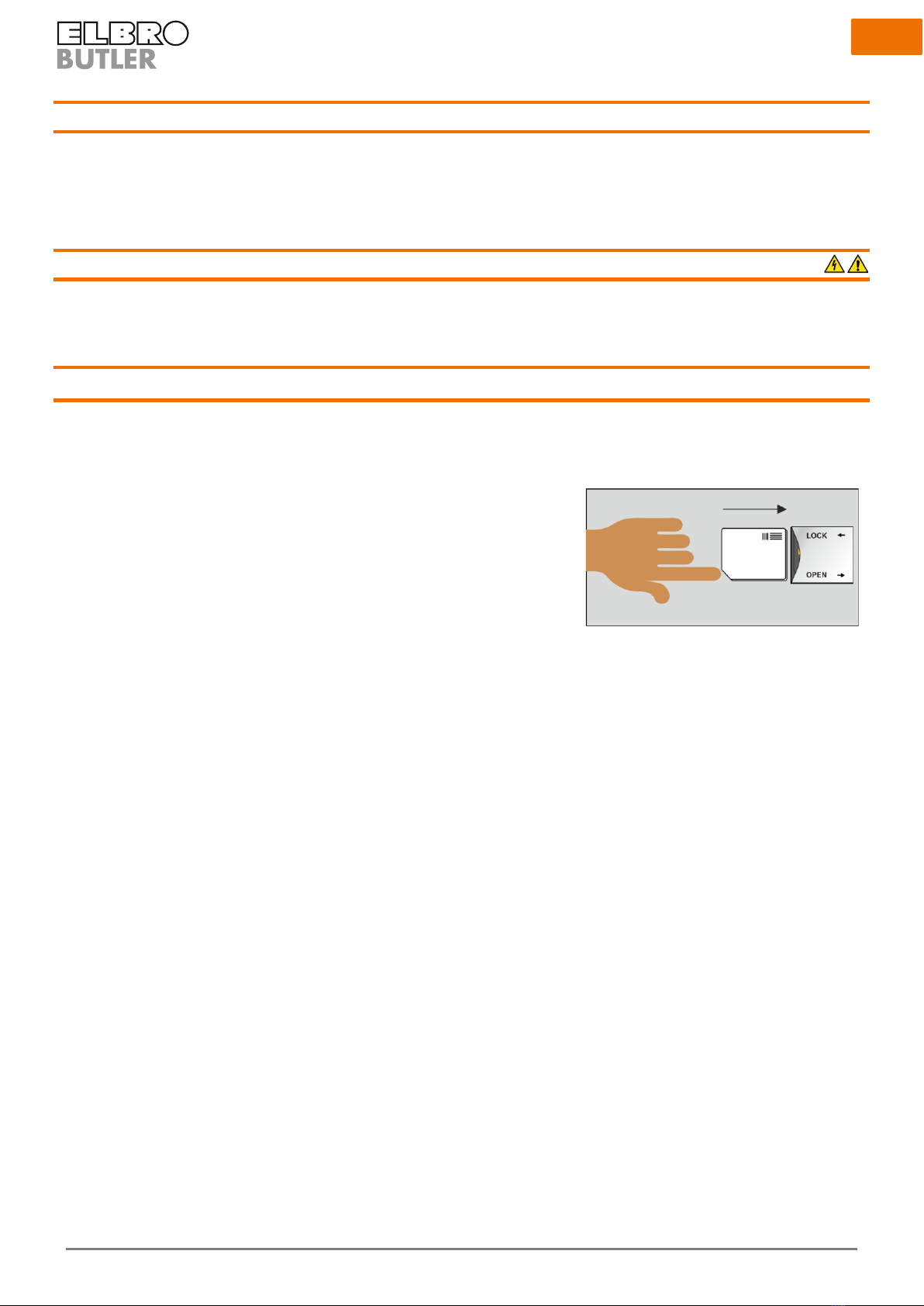
10.1.2 Insertion
Please unlock the SIM slot before inserting the SIM card and open the cover. Afterwards
place the SIM card into the SIM slot with the gold contacts pointing downwards (see illus-
tration). Close and lock the cover.
6
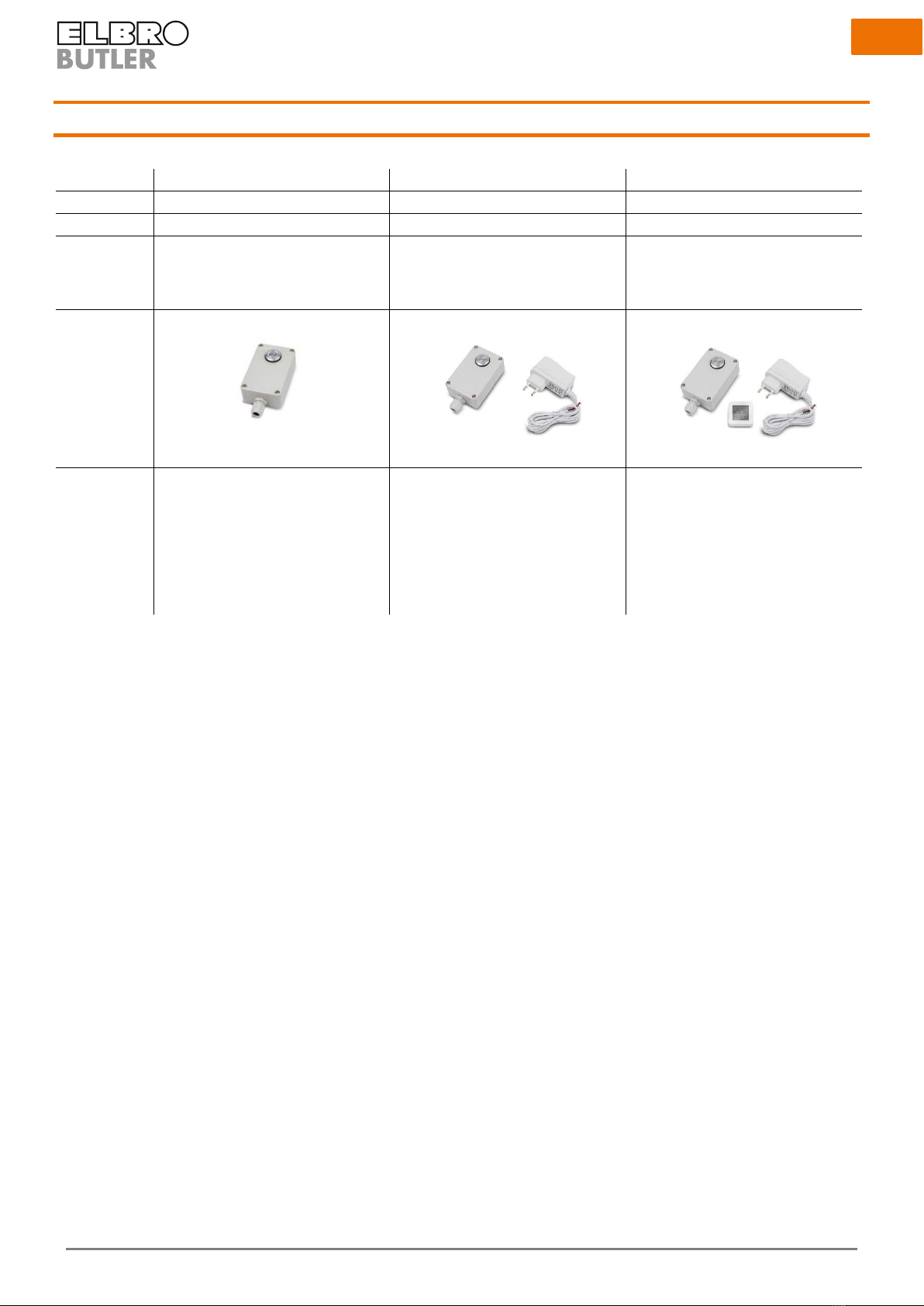
11 Overview of article set contents
Model
SMSB131BW
SMSB131BW-K1
SMSB131BW-K2
E-No.
539 109 500
539 109 510
539 109 520
EAN No.
7611664188893
7611664189166
7611664189173
Description
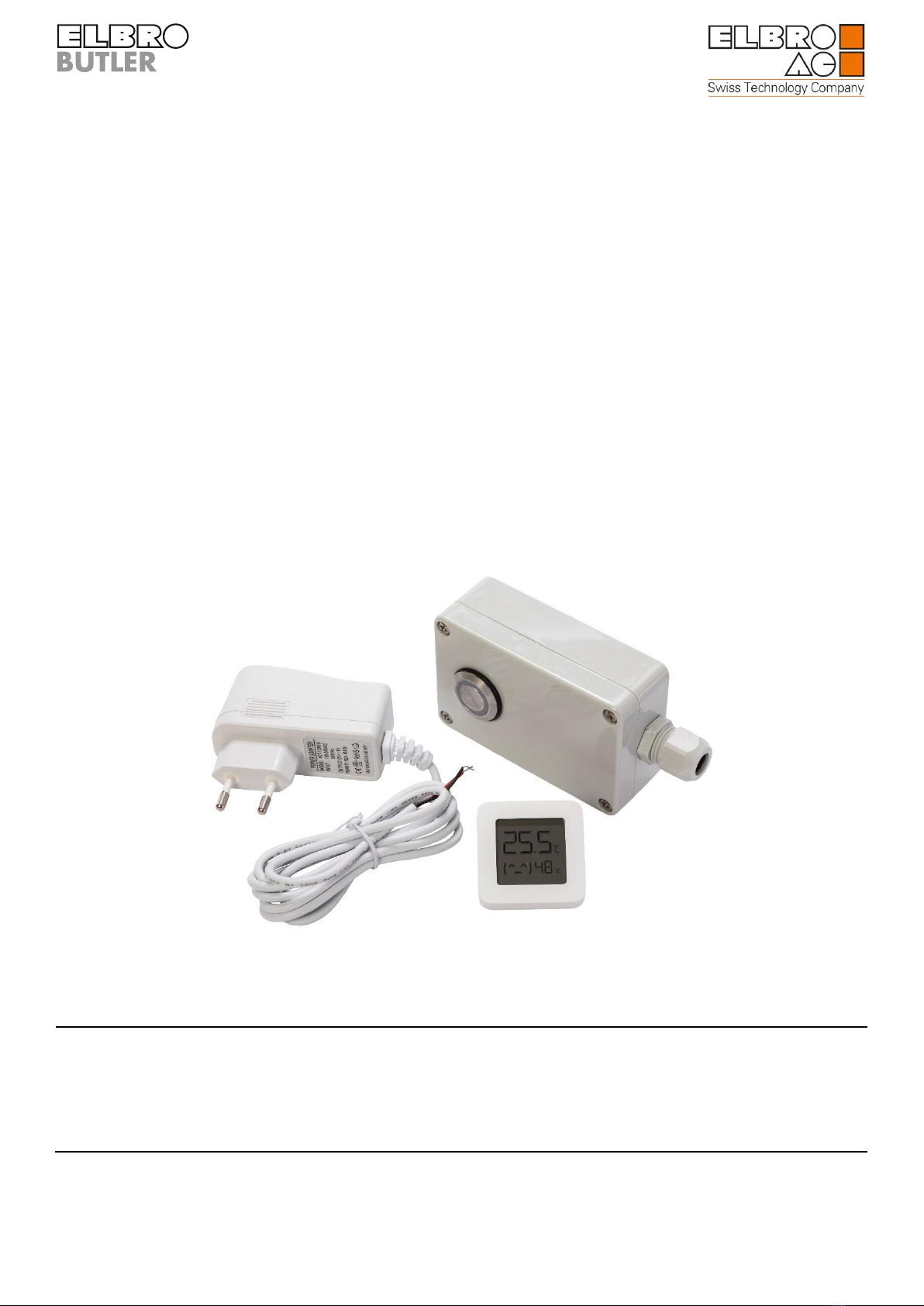
switchButler WiFi & Bluetooth 1/3/1
channels, GSM/UMTS/LTE
switchButler WiFi & Bluetooth 1/3/1
channels, GSM/UMTS/LTE with power
supply unit
switchButler WiFi & Bluetooth 1/3/1
channels, GSM/UMTS/LTE with power
supply unit, temperature and humidity
sensor
Picture
Scope of supply
•SMSB131BW remote control unit
•M16 cable gland
•M16 grommet
•Quick instructions
•Antenna (integrated)
•SMSB131BW remote control unit
•M16 cable gland
•M16 grommet
•Quick instructions
•Antenna (integrated)
•Power supply unit
•SMSB131BW remote control unit
•M16 cable gland
•M16 grommet
•Quick instructions
•Antenna (integrated)
•Power supply unit
•Bluetooth temperature and hu-
midity sensor
7
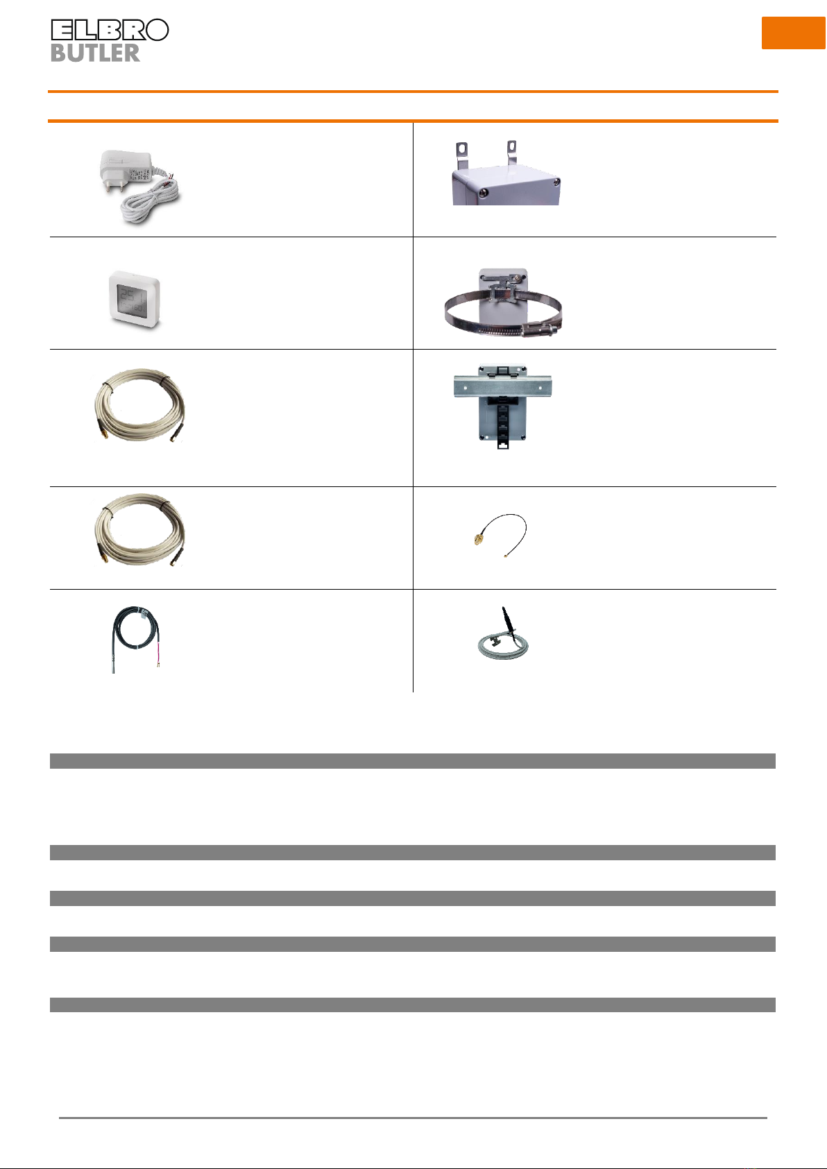
12 Accessories
SMSBNE12-01
E-No. 960 900 339
SMSBZBW
E-No. tbd
BTH1
E-No. 536 100 500
SMSBZMB
E-No. tbd
SMSBV5-01
E-No. 539 190 050
SMSBZDIN
E-No. tbd
SMSBV10-01
E-No. 539 190 100
SMSBAI-015M
E-No. tbd
SMSB-PT100
E-No. tbd
SMSBAI-3M-LTE
E-No. tbd
Article No.
E-No.
Description
Power supply units
SMSBNE12-01
960 900 339
Plug-in power supply 230VAC /12VDC / 1 A
SMSBN12UP
960 900 439
Flush-mounted power supply unit 230VAC /12VDC /
500 mA
SMSBNE12-01
960 900 339
Power supply unit DIN rail mounting 230VAC /12VDC /
1 A
Sensors
BTH1
536 100 500
Bluetooth temperature and humidity sensor
SMSB-PT100
tbd
Temperature sensor PT100, PVC cable, 1.5 m, grey
Extensions
SMSBV5-01
539 190 050
SMA antenna extension with 5m, cable M/F
SMSBV10-01
539 190 100
SMA antenna extension with 10m, cable M/F
Antennas
SMSBAI-3M-LTE
tbd
Multiband antenna with wall mounting bracket, 3 m
cable SMA-M plug LTE, GSM, UMTS
SMSBAI-015M
tbd
Cable adapter IPX-SMA 150 mm, black
Assembly accessories
SMSBZBW
tbd
M4 stainless steel mounting bracket, 2 pieces
SMSBZMB
tbd
Stainless steel rod fastening set, clamping range 40-
320 mm, incl. screws and washers
SMSBZDIN
tbd
DIN rail adapter, plastic, black

9
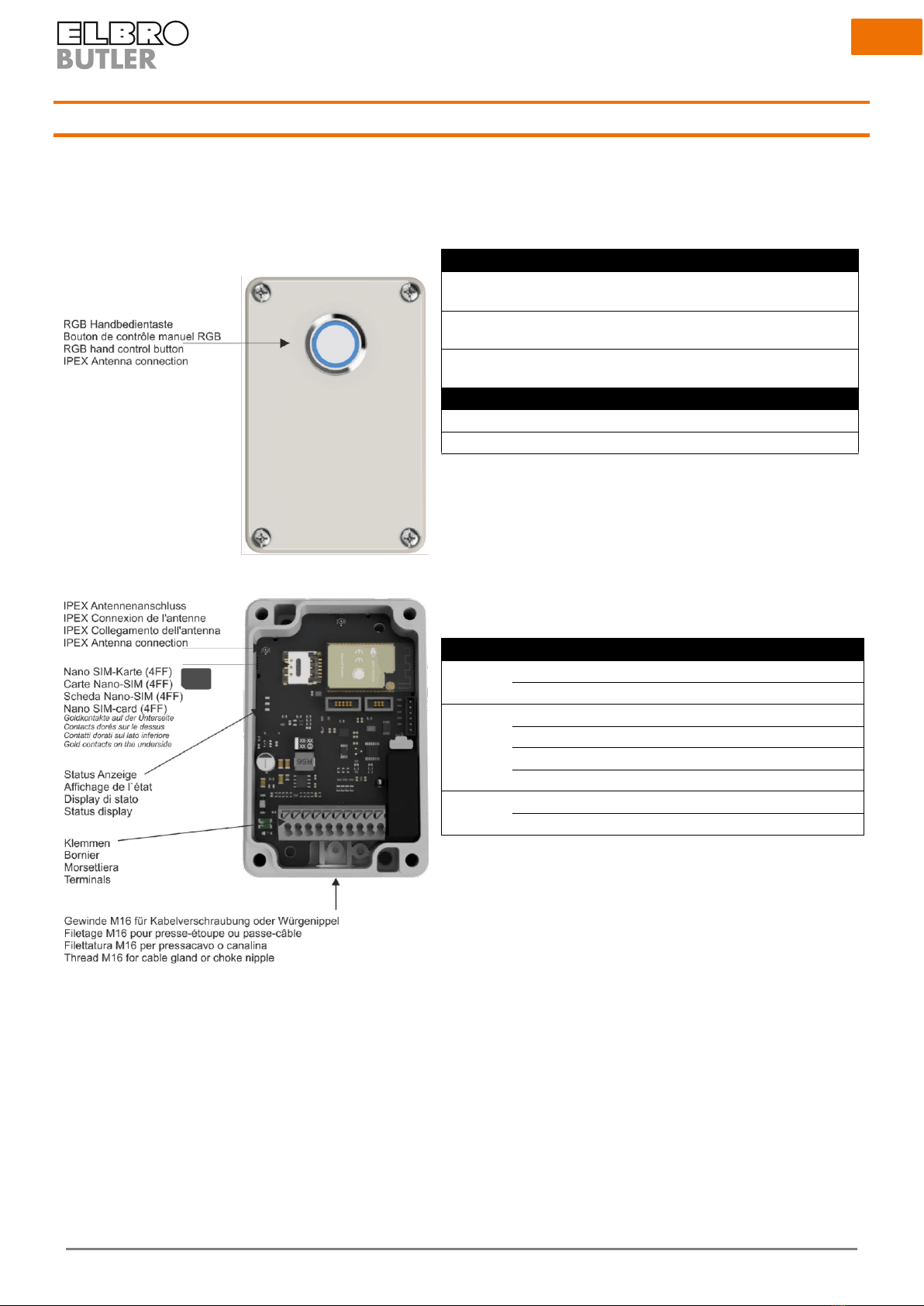
14 Interfaces
1. Manual control button
For the manual control of the relay, reset to the factory setting and status
display.
Function
Operation
Switching the relay on/off
Press manual control button for
2 s
Reset
Press manual control button for
10 s, flashing blue
Factory setting
Press manual control button for
30 s, flashing red
Status
Meaning
Red
Relay off
Green
Relay on
2. IPEX antenna connection
Connection for antenna extension in accordance with accessories
3. Sim card holder
Nano SIM card (4FF) insertion as specified in Chapter 9.6
4. Status display
Indicates the system status
System
LED
Status
Power
On
Ok
Off
Error
Network
On
Search network
200 ms On,200 ms Off
Data transmitted, 4G registered
200 ms On,200 ms Off
2G/3G registered
Off
Switched off, standby mode
CPU
On
Ok
Off
Error
5. Clamps
8 x 14 to 20 (AWG) 2.08 to 0.518 (mm²)
6. M16 thread
:
10
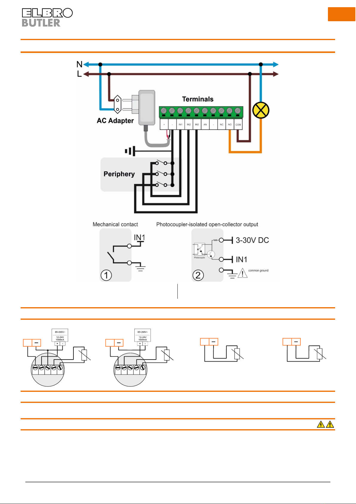
15 Installation diagram
Zero-potential, mechanical contact, e.g. pressure switch, tempera-
ture switch, limit switch, pushbutton, relay output
Voltage output contact, e.g. PLC.
15.1 Analog input
15.2 Digital inputs
The digital inputs serve to monitor systems and devices. Via a potential-free contact in the periphery, which can be programmed as NO contact
or NC contact, the users defined can be alerted via SMS or email. Wire the inputs as shown in the installation diagram.
15.3 Relay output
The installation instructions must be strictly observed with regard to the nameplate data (see corresponding chapter).
0..10V
0..1 0V + 24 V G N D S1 S2
probe
transmitter
AN1
1 2 3 4 5
ONON
0..20mA
LO O P S1 S2
transmitter
LO O P
-+
probe
AN1
S1 S2
probe
1 2 3 4 5
ONON
AN1
probe
Pt100
1 2 3 4 5
ONON
Pt1000
AN1
probe
1 2 3 4 5
ONON
5
11
16 Programming
16.1 Getting started
In general, the SMSB131BW is ready for operation without having to be programmed. Basic commands such as switching on and off can also be
carried out without prior programming. However, if you wish to program these functions, please download the App for your Android or iOS
smartphone. Please connect your SMSB131BW to the power supply unit/the power supply as specified in the instructions.
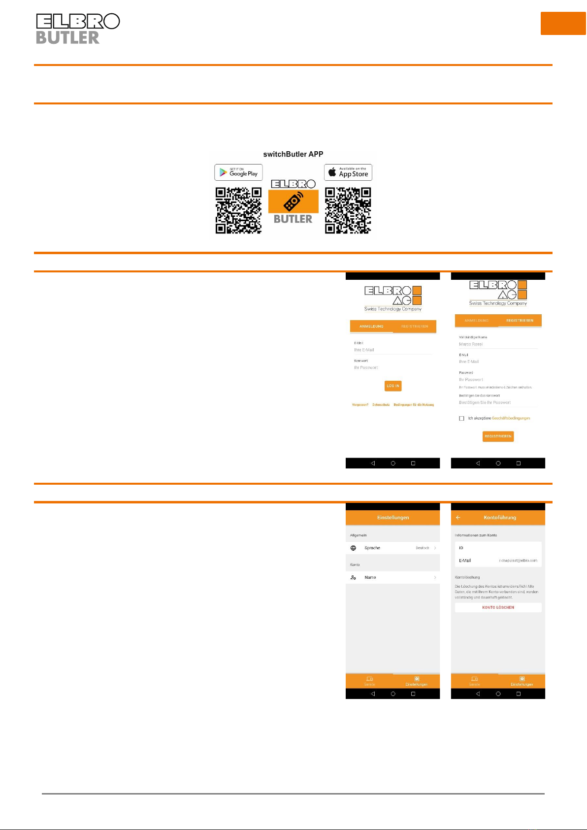
16.2 Registration
Register in the App once.
16.3 Settings
In the settings you select the language for the App; you can also delete your ac-
count here.

12
16.4 Coupling the device via bluetooth
After you have registered and logged in successfully, you can view the devices
available via bluetooth in your proximity. To make the SMSB131BW visible and
allow for successful coupling, it has to be connected to the power supply as speci-
fied in the instructions. Please select the device which you wish to couple.
The RSSI value stands for “Received Signal Strength Indicator” (indicator for the
received signal strength) - the lower the value, the better the connection.
16.5 System status
16.5.1 I/O- status
Overall view of the status indication for the inputs and outputs of the SMSB131BW.
The temperature and humidity indications refer to the internally mounted sensor.
The values do not refer to an external sensor.
16.5.2 LTE module status
Details regarding the network of the mobile provider and the telephone status.
Here, important information such as the signal strength, provider, remaining credit
and the technology used is displayed.

13
16.6 System settings
16.6.1 Interface options
Here you can carry out relevant safety and comfort settings. Name your device
individually and define an alphanumerical password for incoming text messages.
Define the colour and intensity of the pushbutton on the front according to your
wishes.
If you use a prepaid SIM, you can activate the credit query function to continuously
monitor your current costs.
Query code
Swisscom
*130#
Sunrise
*121#
Salt
Service is not supported
16.6.2 User
This list contains the personal data of the users that are authorised to receive alarm
messages. Every user’s profile can be created individually and changed any time.
In order to edit or delete an existing profile, just swipe to the right.
Functions
Notification/connection
Relay
•In/off
•Pulse switching
•Automatic switching (logic)
•At an incoming call
Digital input 1
•Potential-free contact as NO or NC
contact
•Voltage-dependent contact
Digital input 2
•Potential-free contact as NO or NC
contact
•Voltage-dependent contact
Digital input 3
•Potential-free contact as NO or NC
contact
•Voltage-dependent contact
Analog input
•0-10 V
•0-20 mA; 4-20 mA,
•PT100
•PT1000
Power failure message
•In the event of a power at the volt-
age supply
•In the case of voltage events
Periodic status message
•Notification on the status at regular
time intervals
Wireless sensors
•In the case of a temperature or hu-
midity alarm
14
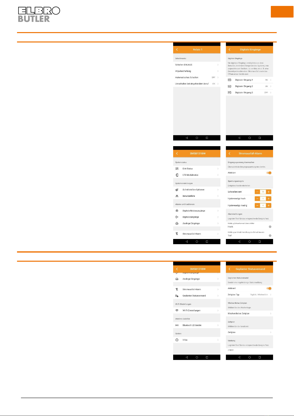
16.7 Alarms and functions
16.7.1 Relay
Configure your relay here. Here you can choose between ON/OFF, pulse switching,
automatic switching or switching at an incoming call. In order to be able to use this
function, please activate the relay permission for the desired user.
16.7.2 Digital inputs
The digital inputs can be programmed individually and independently of each
other. Select the type of contact and define the alarm text and a possible delay for
an alarm event.
• Potential-free contact as NO or NC contact
• Voltage-dependent contact
16.7.3 Analog input
The SMSB131BW is provided with an analog input that can be configured with
probes 0-10 V, 0-20 mA, 4-20 mA, PT100 or PT1000.
16.7.4 Power failure message
Input voltage
This function allows for sending a notification to users defined in advance when a
power failure occurs and/or ends. A potential power failure is bridged in the device
by means of a capacitor.
Voltage event
Additionally, the voltage supply can be monitored. This function is useful in partic-
ular for systems separated from the network such as self-sufficient traffic surveil-
lance systems. In this way, for example the 12 V battery supplied by the photovol-
taic system can be monitored.
16.8 Periodic status message
You can use this function to have a message sent to activated users at regular in-
tervals (daily, weekly or monthly). This mode is helpful to permanently monitor an
installation or to avoid the expiry of SIM cards when they are not used for a longer
time.
15
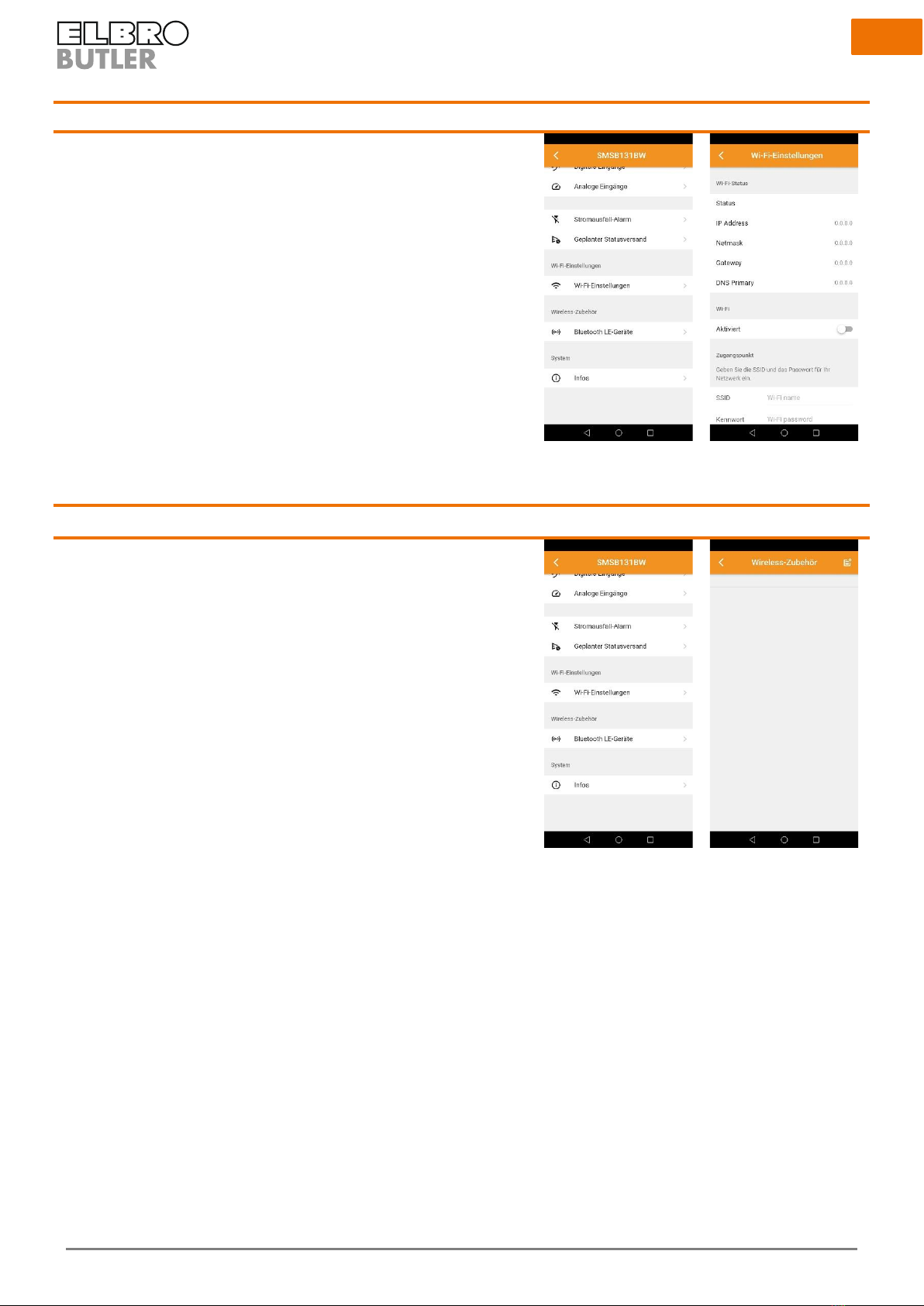
16.9 Wi-Fi settings
Activate Wi-Fi and enter the SSID and the password for the network. In the case of
public networks, leave the password field empty. The advanced network settings
provide you with the possibility of allocating a static IP address to the device.
17 Wireless accessories
Connection of wireless sensors via bluetooth. Take the device near the telephone
and press the “Add” button at the top right. After successful coupling, you can per-
sonalise the wireless sensors. Define your own temperature and humidity alarm.

16
18 System
18.1.1 System information
Indication of the relevant system information.
Model
Manufacturer
Serial number
Hardware revision
Firmware revision
Web browser revision
18.1.2 System update
To carry out the update, the device first must be connected to a Wi-Fi network that
is connected to the Internet. You can also use a hotspot on a mobile phone. Then
you select “Check update”, so your device will check automatically whether a new
firmware is available.

17
19 SMS commands
The SMSB131BW is provided with various configuration and control commands that can be sent via SMS. The command message is protected
by a password. The format of the command message is as follows:
[PASSWORD]#[COMMAND] Example: 0000#1
The default password for the command message is →0000
The password always has a length of 4 characters plus #: The hash is a required separator. You can replace it by the 'point’ character.
The following table shows a list of SMS commands with descriptions and examples:
Command
Description
Example
[PW]#0
Switches off the relay
0000#0
[PW]#1
Switches on the relay
0000#1
[PW]#?
Status query
0000#?
[PW]#A[8-30]
Activates the thermostat threshold value
0000#A23
[PW]#A0
Deactivates the thermostat threshold value
0000#A0
[PW]#H[1-99]
Activates the hygrostat threshold value
0000#H50
[PW]#H0
Deactivates the hygrostat threshold value
0000#H0
20 Manual switch
20.1.1 Switching the relay in manual mode
In order to switch the relay manually, press the button for 2 seconds and let go of it again. The button reports back the relay status optically to
you, see “Interfaces” chapter.
20.1.2 Manual restart
To restart the SMSB131BW without losing the settings, keep the button pressed for at least 10 seconds and let go of it again. The button reports
back the relay restart optically to you, see “Interfaces” chapter.
20.1.3 Manual restart to default setting
To delete and reset all settings, keep the button pressed for at least 30 seconds and let go of it again. The button reports back the reset optically
to you, see “Interfaces” chapter.

18
21 Technical data
Radio
4G LTE Cat 1, GNSS receiver ready (on request)
Frequencies:
•LTE-TDD B34/B38/B39/B40/B41
•LTE-FDD
•B1/B2/B3/B4/B5/B7/B8/B12/B13/
•B18/B19/B20/B25/B26/ B28/B66
•UMTS/HSPA+
•B1/B2/B4/B5/B6/B8/B19
•GSM/GPRS/EDGE
•850/900/1800/1900MHz
Wi-Fi range
802.11 b/g/n (802.11n up to 150 Mbps)
Frequencies: 2.4 GHz ~ 2.5 GHz
Bluetooth
Bluetooth v4.2 BR/EDR and BLE
SIM card slot
Nano SIM (4FF) foldable SIM card connection (SIM card not included in the scope of supply)
Memory slot
Micro SD card (not included in the scope of supply) for GNSS recordings or logging (optional).
LTE antenna
Integrated, optionally an external antenna with IPX connection can be installed.
Clamps
8 x 14 to 20 (AWG) 2.08 to 0.518 (mm²)
Power supply
Supply voltage: 12÷24V DC; extended 9÷30V DC
Current: IMAX = 1000 mA
Power supply with reverse polarity protection and short-circuit-proof
Outputs
1 relay form C (SPDT-NO, NC)
Rated load:
•10 A at 250 VAC, (NO) ohmic load
•8 A at 250 VAC, ohmic load
•5 A at 30 VDC, ohmic load
Inputs
3 programmable digital inputs (potential-free/voltage-dependent)
1 analog input: 0-10 V; 0-20 mA; 4-20 mA; PT100; PT1000
General characteristics
Information regarding the colour
•Colour description light grey
•RAL code 7035
Information regarding the material
•Housing material polycarbonate
•Screw material stainless steel V2 A
•Silicone-free
•Halogen-free
•Material UL listed
•UV resistant
Temperature resistance and areas of application
•Continuous operating temperature max. 80 °C
•Continuous operating temperature min. -40 °C
•Suitable for inside/outside use
Weight
•180 g
Dimension
•98x64x35 mm
Customs tariff number
•85437000

19
Country of origin
•CH
Technical characteristics of the housing
•Degree of protection
▪IP67 with cable gland
▪IP55 with grommet
•Standard of protection class DIN EN 60529
•Impact strength IK08
•Flame retardancy V2
•UL approval UL 94
•Protection class II
•Seal foamed, seamless
•Captive cover screws
•Assembly tool PZ2
•Tightening torque cover screws max. 2.00 Nm
•Tightening torque cover screws min. 1.00 Nm
Consumption (typical values)
•Voltage supply 12V DC
•Standby
•Sending SMS
•Receiving SMS
•Switching relay
•GPRS/UMTS
Declaration of conformity
ELBRO AG hereby declares that the product SMSB131BW complies with the fundamental requirements
and other relevant provisions of the RED Directive
Table of contents
Other ELBRO Control Unit manuals

Popular Control Unit manuals by other brands

Honeywell
Honeywell V4043A manual

Armstrong
Armstrong 320 Installation and Maintenance

National Instruments
National Instruments Phase Matrix PXI-1430B quick start guide

BS&B
BS&B 6400 Instruction and maintenance manual

Advantech
Advantech Network Device USB-4761 Startup manual

AUDAC
AUDAC APC100 MK2 user manual


 8504107 REV C... installation instructions")


