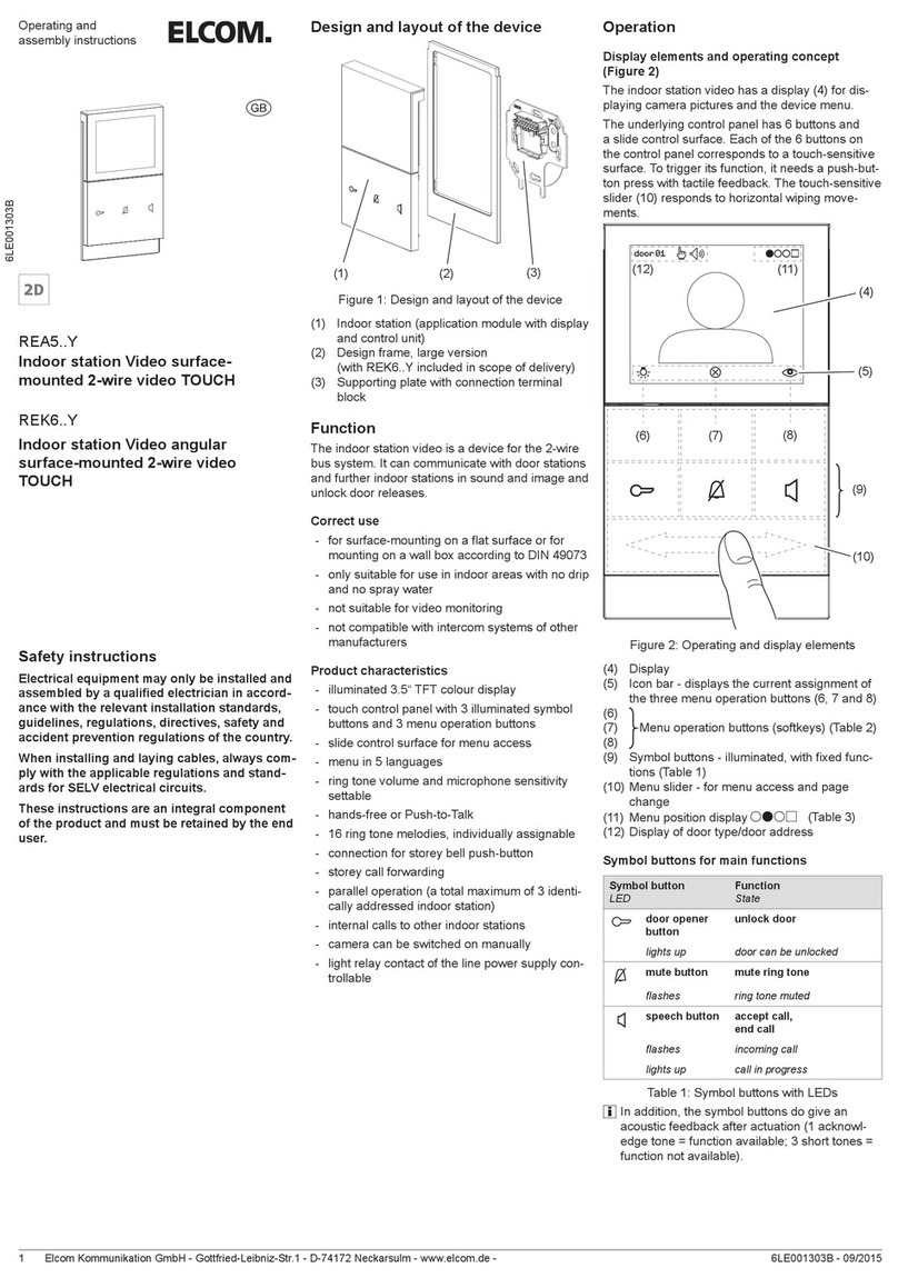
ELCOM RER1 X Series User manual

Elcom Kommunikation GmbH-Zum Gunterstal-66440 BLIESKASTEL-GERMANY - www.elcom.de - 6LE001998A Ind. A - 02/20171
Bedienungs- und
Montageanleitung
Safety instructions
Electrical equipment may only be installed and
assembled by a qualied electrician in accor-
dance with the relevant installation standards,
guidelines, regulations, directives, safety and
accident prevention regulations of the country.
When installing and laying cables, always com-
ply with the applicable regulations and stan-
dards for SELV electrical circuits.
These instructions are an integral component
of the product and must be retained by the end
user.
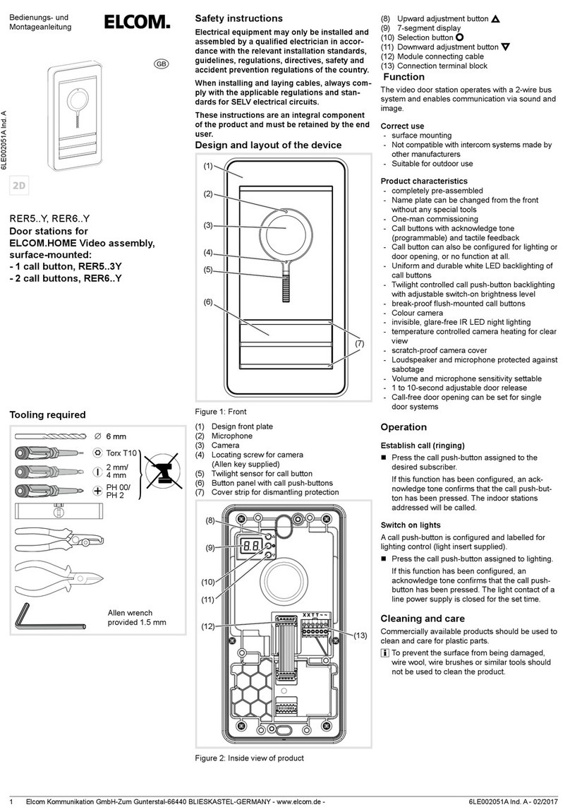
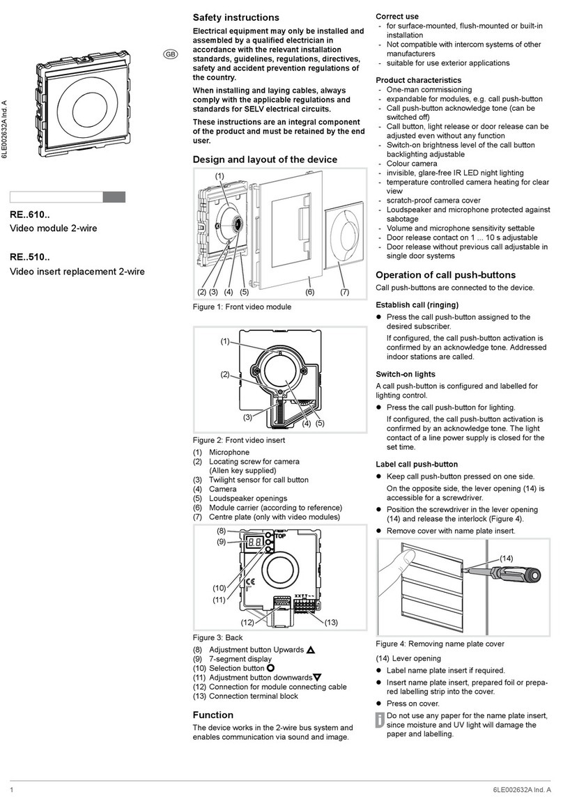
Design and layout of the device
(6)
(3)
(5)
(4)
(2)
(1)
Figure 1: Front
(1) Design front plate
(2) Microphone
(3) Door loudspeaker
(4) Twilight sensor for call button
(5) Button panel with call push-buttons
(6) Cover strip for dismantling protection
(10)
(7)
(8)
(9)
(11)
(12)
Figure 2: Inside view of product
(7) Upward adjustment button
(8) 7-segment display
(9) Selection button
(10) Downward adjustment button
(11) Module connecting cable
(12) Connection terminal block
Function
The audio door station operates with a 2-wire bus
system and enables communication via sound.
Correct use
- surface mounting
- not compatible with intercom systems made by
other manufacturers
- suitable for outdoor use
Product characteristics
- completely pre-assembled
- name plate can be changed from the front
without any special tools
- one-man commissioning
- call buttons with acknowledge tone
(programmable) and tactile feedback
- call button can also be congured for lighting or
door opening, or no function at all
- uniform and durable white LED backlighting of
call buttons
- twilight controlled call push-button backlighting
with adjustable switch-on brightness level
- break-proof ush-mounted call buttons
- loudspeaker and microphone protected against
sabotage
- volume and microphone sensitivity settable
- 1 to 10-second adjustable door release
- call-free door opening can be set for single door
systems
Operation
Switch on lights
Press the call push-button assigned to the
desired subscriber.
If this function has been congured,
an acknowledge tone conrms that the call
push-button has been pressed. The indoor
stations addressed will be called.
Switch-on lights
Press the call push-button assigned to lighting.
If this function has been congured,
an acknowledge tone conrms that the call
push-button has been pressed. The light
contact of a line power supply is closed for the
set time.
Cleaning and care
Commercially available products should be used to
clean and care for plastic parts.
To prevent the surface from being damaged,
wire wool, wire brushes or similar tools should
not be used to clean the product.
z
6LE001998A Ind. A
RER1..X, RER2..X
Door stations for
ELCOM.HOME Audio assembly,
surface-mounted:
- 1 call button RER1..Y
- 2 call buttons RER2..Y
Tooling required
6 mm
Torx T10
PH 00/
PH 2
2 mm/
4 mm

Elcom Kommunikation GmbH-Zum Gunterstal-66440 BLIESKASTEL-GERMANY - www.elcom.de -2
Information for electricians
Installation and electrical connection
DANGER!
Touching live parts in the installation
environment can result in an electric
shock!
An electric shock can be lethal!
Before working on the device or load,
disconnect all associated circuit brea-
kers. Cover all live parts in the area!
ç
When installing door communication systems,
comply with the general safety regulations for tele-
communications systems according to VDE 0800:
- Separate routing of power and door
communication cables with a minimum spacing
of 10 cm
- Partitions between power and door
communication cables in shared cable ducts
- Use of standard telecommunications cables
cables, e.g. J-Y (St) Y with 0.8 mm diameter.
Bus cables
- J-Y(ST)Y or A-2Y(L)2Y
Use wrapped wire pair.
Recommendation: white/yellow
- CAT
Use a pair of twisted wires
Recommendation: orange/white
- YR
Use adjacent wires.
Mounting door station
The connecting cables and indoor stations are
connected to the line power supply in complian-
ce with maximum cable length and attenuation
stipulations.
(see operating instructions of the line
power supply).
Unclip the design front plate (1) using
a at-headed screwdriver (4 mm) (gure 3).
(1)
Figure 3: Unclipping the design front plate
Use a Torx T10 screwdriver.
Loosen the 2 screws (13) in the door station
(gure 4).
(13)
Figure 4: Opening for the rst time 1
(13) Torx T10 screw
Opening for the rst time: insert 2 mm, a at
screwdriver (4 mm) between the front face
and the xing base and then lift it to unlock it
(gure 5).
Figure 5: Opening for the rst time 2
Using a pointy object (tip, screw, rigid copper
wire, etc.), make a hole in the membrane
(14) big enough for the cable to go through
(gure 6).
Thread roughly 170 mm of the cable through.
Position the xing base on the wall in order to
determine where the two xing points should be
(gure 6).
- The xing screws and washers are not
supplied.
- Use Ø 4 mm max. screws with a non-counter-
sunk Ø 8 mm max. head.
WARNING!
Do not use an electric screwdriver.
Use a normal screwdriver without
applying too much pressure.
ç
Pozidriv 2
(14)
Figure 6: Base xing
(14) Feeding the cable through
Connect door station
Remove the connection terminal block (13)
from the audio module (gure 7).
Connect the 2-wire bus cable to the terminals
XX of the connection terminal block (gure 7).
Connect door release to the terminals TT of
the connection terminal block (gure 7 and 8) if
required.
or:
FFor an installation with anti-tamper system,
connect the door release to the contact of
the line power supply (gure 9).
To ensure protection against tampering, the
door release power lead must not be threaded
through the door station.
For call push-button backlighting connect 12 V~
lead from the power transformer to the termi-
nals ~~ of the connection terminal block
(gure 7, 8 and 9).
(12)
Figure 7: wired connection terminal block
Information about how to connect the door
station as a oor station can be found in the
operating instructions of the line power supply.
Attach connection terminal block to audio insert.

Elcom Kommunikation GmbH-Zum Gunterstal-66440 BLIESKASTEL-GERMANY - www.elcom.de - 6LE001998A Ind. A - 10/20163
Switching and wiring diagram symbols
Line power supply RMD
Power transformer
Door release
Door station audio
Twisted wire pair, for 2-wire devices
(recommendation: white/yellow wire pair)
Untwisted wire pair, for e.g. for door release
- The earthing of the Bus line power supply (PE)
increases interference resistance.
- The Bus line power supply must be installed
far away from any sources of electromagnetic
disturbance (Wireless telephony and radio,
hi- equipment, video, computing, etc.).
Figure 8: Door release connection on the door
station
Figure 9: Connection of door station with
manipulation-protected door release
Call up and change system settings
On the back of the audio module, there are 3 but-
tons and a 2-digit 7-segment display (gure 2) for
the system (gure 11) settings.
Press / button.
Device turns to setting mode. The rst menu
entry is displayed.
The reading direction of the 7-segment display
varies by 180° depending on which button /
you start with.
Select the desired menu entry with / .
Conrm the selection with .
The 7-segments display goes dark if there is no
actuation for 5 seconds. Settings are applied.
The device returns to normal operation.
Setting the values
The menu entry to be set is conrmed and ashes
alternately with the value to be set.
Press / button.
Press briey: change the value by one step.
Press and hold: run through values. Scrolling
stops when the button is released.
Conrm set value with
The device applies the setting and returns to
the previous menu entry.
Automatic call push-button addressing
The call push-button and connector on the back
are addressed by the automatic call push-button
addressing as follows. Addressing is performed
automatically from top to bottom (gure 10).
Door stations are automatically pre-congured
at the factory.
The menu entry is conrmed. ashes alter-
nately with the entry for cancel.
With / select the entry for automatic
addressing.
Conrm with .
During the addressing, the display ickers.
Afterwards the display returns to the previous
menu entry .
Figure 10: Module address and automatic call
push-button addressing
Set individual call
push-button
address/function
The menu entry Set individual call push-button
address/function is conrmed and ashes.
Conrm the call push-button to be set.
The menu entry ashes alternately with the
current address/function.
With / select the required address ...
or function for light push-button, for
door release push-button or for no function.
Internal call 1) :
In the door communication system, internal
calls from indoor station to indoor station are
possible. Unlike comfort indoor stations only the
xed addresses and are available as call
destination for the internal call.
1) Requires the appropriate default setting by the installer
(see: Indoor station/Expanded settings).
Conrm set address/function with .
The device applies the setting and returns to
the previous menu entry. .
Display of saved error codes
Audio insert and call push-button module errors
that occur during operation are stored in the the
error memory of the audio insert for diagnosis.
Select menu entry with button / and
conrm with
If no error code has been saved, is
displayed for 2 seconds followed by again.
If error codes have been saved, ashes
and the module address and error code are
displayed.
Press button / , to call up further error
codes if necessary.
Press button to return to menu entry .
Error
code
Error cause Corrective
actions
Communication error
between audio insert
and call push-button
module. Once the
error has occurred 3
times, the system is
reset automatically
and the error code is
generated.
If the error
continues, the
call push-button
module must be
replaced and
the addressing
operation
performed again.
Call button stuck. Check call push-
button module,
and if there is a
defect, replace
and address.
Call push-button
address failed to write
in call push-button
module.
If the error per-
sists, the call
push-button
module must be
replaced and
addressed.
Table 1: Error codes and corrective actions
The memory should only be deleted once 5
error codes have been stored, so that new error
codes can be saved.
Identical error codes are only saved once.
Elcom Kommunikation GmbH-Zum Gunterstal-66440 BLIESKASTEL-GERMANY - www.elcom.de -4
Individual call push-
button address/function
Automatic call push-
button addressing
Door speaker
volume
Microphone
sensitivity
Operating sig-
nal sound volume
Door release
unlocking time
Door release
function
set
door address
Camera present
Call push-button
Backlighting settings
(switch-on brightness
level)
Display error codes
(max. 5 can be saved)
Reset error codes
factory setting
Conrm the call push-
button to be set
... =
Call push-button address
= Light push-button
=
Door release push-but
ton
= no function
Address/Function
saved,
is displayed
= Cancel
= Start addressing
Addressing executed/can-
celled, is displayed
...
Default setting
Volume set,
is displayed
...
Default setting
Sensitivity set.
is displayed
...
= Acoustic signal off
Default setting
Volume set,
is displayed
... Seconds
Default setting seconds
Unlocking time set,
is displayed
= only with door call
= also without door call 2)
Default setting
Door release function is set,
is displayed
x... x
x = received line
address
Default setting
Door address set,
is displayed
= No camera
= with camera
Default setting: Audio
Video
Camera option set,
is displayed
...
= Off
= lowest value
= highest value
= always on
Default setting
Backlighting set,
is displayed
... Error codes
=
communication module
= sticking call button
= module address
= no error present
= Cancel
= Reset
Error codes were deleted,
is deleted
Error codes were displayed,
is displayed
= Cancel
= Reset
Reset to the factory setting, in-
dication goes out
2) Door station call-free door-opening function only possible in single door systems.
Figure 11: Overview of system settings
Internal call 1) :
In the door communication system,
internal calls from indoor station to
indoor station are possible. Unlike
comfort indoor stations only the xed
addresses and are available
as call destination for the internal call.
1) Requires the appropriate default setting by
the installer (see: Indoor station/Expanded
settings).

Elcom Kommunikation GmbH-Zum Gunterstal-66440 BLIESKASTEL-GERMANY - www.elcom.de - 6LE001998A Ind. A - 10/20165
Install door station
The system settings are complete.
Use a Torx T10 screwdriver.
Position the door station on the base and
tighten the two screws in the front plate
(gure 12).
Figure 12: Installing door station
Clip the design front plate (1) on to the door
station making sure that the unclipping slot (15)
is pointing downwards (gure 13).
(15)
(1)
Figure 13: Clipping the design front plate on to the
base.
(15) Unclipping slot
Label call push-button
Press one side of the call push-button.
The other side can be levered open (16) using
a screwdriver.
Insert the screwdriver into the lever opening
system (16) and unlock the button (gure 14).
Remove cover with name plate insert.
(16)
Figure 14: Removing name plate cover
(16) Lever opening system
Label name plate insert if required.
Place a name plate or label inside the cover
and press down on the cover.
Do not use a paper name plate or label as it
may be damaged by damp and UV light along
with the writing on it.
Use UV-resistant media and laser printing
or marking devices for the labelling:
- small buttons - 12 mm
- medium buttons - 30 mm
It is advisable to use white writing on a black
background.
Dismantle call push-button module cover
During cleaning or replacement, the call push-but-
ton module cover can be dismantled from the front.
Lever open the top and bottom of the cover
strips (6) and remove them (gure 15).
(6)
Figure 15: Removing cover strips
Use a screwdriver to lever open the push-but-
ton module cover and remove it from the front
(gure 16).
(17)
Figure 16: Dismantling the call push-button module
cover
(17) Call push-button module cover
Defective covers can only be replaced by co-
vers with the same number of push-buttons.
Remove the module to be replaced and install
the new module in reverse order.

Elcom Kommunikation GmbH-Zum Gunterstal-66440 BLIESKASTEL-GERMANY - www.elcom.de -6
Replace a module
Dismantle the door station (gure 3).
Remove the connection terminal block (12)
from the video insert.
Loosen the screws (18) on the rear base of the
modules (19) using a screwdriver and remove
the base (gure 17).
Remove the connecting cable connectors from
the module (12) to be exchanged (gure 2).
(18) (19)
Figure 17: Module base dismantling
(18) Vis
(19) Module base
The audio module and the call push-button module
can be removed.
Remove the module to be replaced and install
the new module in reverse order.
Automatic or manual addressing of the module
is required to operate the door station.
Appendix
Technical data
Operating voltage 22 ... 24 V=
Current consumption audio insert
Stand-by 5 mA
Current consumption audio insert
Operation 110 mA
Current name plate lighting
per call push-button module 45 mA
Menu
setting
Backlighting On Backlighting Off
0 Permanent Off
1
2
3
4
5
6
7
8
9
≈ 750 lx
.
.
.
.
.
.
.
≈ 60 lx
≈ 1600 lx
.
.
.
.
.
.
.
≈ 110 lx
10 Permanent On
Table 2: Switch-on brightness level name plate-
lighting
Door release contact T/T potential-free max. 24 V/1 A
Door release unlocking time 1 ... 10 s
Degree of protection IP 54
Degree of protection IK07
Average degree of humidity from 5% to 75%
without condensation at 25°C,
can vary between 85% and 95%
for 30 days in the year
Operating temperature -20°C … +55°C
Storage/transport temperature -30°C … +80°C
Connecting terminals
for conductor diameter 0.5 ... 0.8 mm
Dimensions:
Small call push-button 75.8 x 14.5 mm
Small name plate insert 72.1 x 12 mm
Medium call push-button 75.8 x 32.6 mm
Medium name plate insert 72.1 x 30.1 mm
Width of name plate insert max. 0.5 mm
Door station dimensions
(W x H x D) 100 x 191 x 29.5 mm

Elcom Kommunikation GmbH-Zum Gunterstal-66440 BLIESKASTEL-GERMANY - www.elcom.de - 6LE001998A Ind. A - 10/20167

Elcom Kommunikation GmbH-Zum Gunterstal-66440 BLIESKASTEL-GERMANY - www.elcom.de - 6LE001998A Ind. A - 02/2017
This manual suits for next models
1
Table of contents
Other ELCOM Intercom System manuals

ELCOM
ELCOM REK241Y User manual

ELCOM
ELCOM RER5 Y Series User manual

ELCOM
ELCOM BVM-100 User manual

ELCOM
ELCOM ELA-100 User manual

ELCOM
ELCOM BHT-200 User manual

ELCOM
ELCOM RE 610Y Series Product guide

ELCOM
ELCOM RE 610 Series User manual

ELCOM
ELCOM REA1 Y Series User manual

ELCOM
ELCOM i2 AUDIO BFT-200 User manual

ELCOM
ELCOM REA1 Y Series Product guide