manuals.online logo
Brands
  1. Home
  2. •
  3. Brands
  4. •
  5. ELCOM
  6. •
  7. Intercom System
  8. •
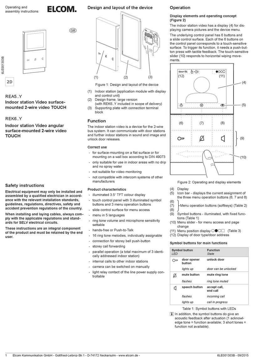
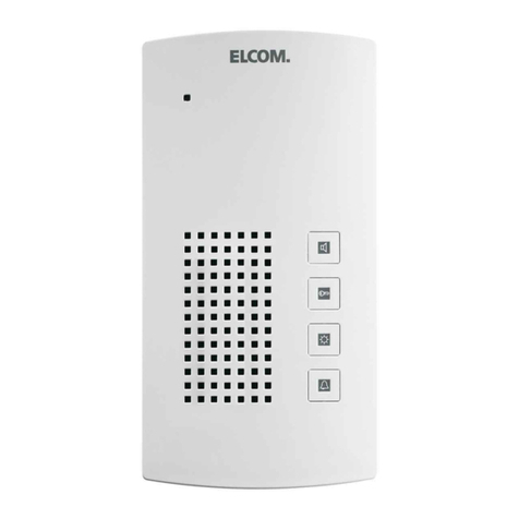
  9. ELCOM REA1 Y Series Product guide

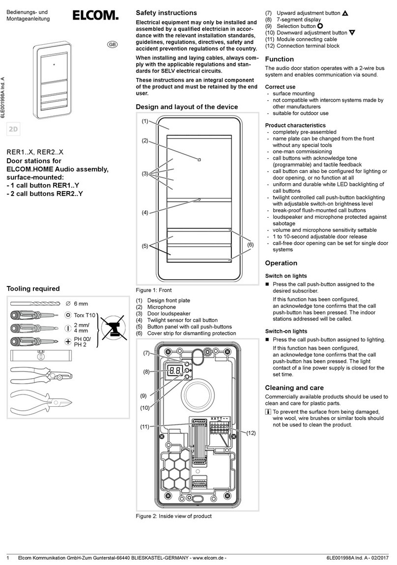
ELCOM REA1 Y Series Product guide

Elcom Kommunikation GmbH - Gottfried-Leibniz-Str.1 - D-74172 Neckarsulm - www.elcom.de - 6LE000708B - 09/20151
Operating and
assembly instructions
§
6LE000708B
REA1..Y
Indoor station Audio surface-
mounted 2Wire, TOUCH
REK2..Y
Indoor station Audio angular
surface-mounted 2Wire, TOUCH
Safety instructions
Electrical equipment may only be installed and
assembled by a qualied electrician in accord-
ance with the relevant installation standards,
guidelines, regulations, directives, safety and
accident prevention regulations of the country.
When installing and laying cables, always com-
ply with the applicable regulations and stand-
ards for SELV electrical circuits.
These instructions are an integral component
of the product and must be retained by the end
user.
Design and layout of the device
(3)
(1) (2)
(4)
Figure 1: Design and layout of the device
(1) Indoor station (operating unit)
(2) Design frame
(with REK2..Y included in scope of delivery)
(3) Supporting plate with connection terminal
block
(4) Microphone
Function
The indoor station audio is a device for the 2-wire
bus system. It can communicate with door stations
and further indoor stations and unlock door releas-
es.
Correct use
- For surface-mounting on a at surface or for
mounting on a wall box according to DIN 49073
- Only suitable for use in indoor areas with no
drip and no spray water
- Not compatible with door communication sys-
tems of other manufacturers
Product characteristics
- Touch control panel with 6 symbol buttons, 3
are illuminated
- Hands-free or Push-to-Talk
- Ring tone volume and microphone sensitivity
can be adjusted
- 16 ring tone melodies, individually assignable
- Connection for storey bell push-button
- storey call forwarding
- Parallel operation (a total maximum of 3 identi-
cally addressed indoor stations)
- Internal calls to other indoor stations
- Light button for activation of the light relay con-
tact
Operation
Operating concept
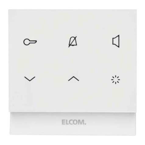
Each of the 6 symbol buttons on the control panel
(Figure 2) corresponds to a touch-sensitive sur-
face. To trigger its function, it needs a push-button
press with tactile feedback.
Figure 2: Control panel
All basic functions can be called up directly via the
respective symbol button:
Symbol button
LED
Function
State
door opener2)
button
unlock door
lights up door can be unlocked
mute button2) mute ring tone
ashes ring tone muted
speech
button2)
accept call,
end call,
switch on internal call mode
ashes
incoming call,
internal call mode switched on
lights up call connection active
adjustment
button down
decrease value,
Initiate internal call F/E
adjustment
button up
increase value,
Initiate internal call F/F
light button2) switch on light1),
terminate setting mode
1) requires a corresponding installation
2) with acknowledge tone
Table 1: Control panel buttons
By pressing the + buttons simultaneously
the setting mode is activated (see audio settings).

In addition, the buttons2) do give an acoustic
feedback after actuation:
- 1 acknowledge tone = function available
- 3 short tones = function not available
- 3 recurring tones = internal call mode
Elcom Kommunikation GmbH - Gottfried-Leibniz-Str.1 - D-74172 Neckarsulm - www.elcom.de - 6LE000708B - 09/20152
Application 1: Door call
Outside on the door station the assigned call
push-button is pressed.
The indoor station signals a door call:
The ring tone melody sounds.
The LED ashes and the lights up.

Ring tone and LEDs signal the door call for a
max. of 90 seconds.
Accepting door call and establishing call
Press the speech button .
A call to the door station is established.
The LED lights up permanently. The call
connection is established (max. call duration
3 minutes).
To end the call, press the speech button again.
Call connection and video connection are
terminated.
or:
Open door
Press door opener button.
The door of the calling door station is unlocked
and can be opened. An active call is terminat-
ed automatically approx. 10 seconds after the
unlocking.

Direct door release: In systems with only one
door station, the door can be unlocked even
without a preceding door call if the door station
has been congured accordingly.
Switch-on lights
The light (e.g. stair light) can be switched on if the
associated automatic light is connected to the line
power supply with relay.
Press light button.
The light is switched on1).
1) requires a corresponding installation
Mute ring tone
The ring tone can be muted if necessary.
The indoor station is in standby mode.
Press the mute button.
The LED ashes. The ring tone melody is
deactivated.
Press the mute button once again.
The LED goes out. The ring tone melody is
reactivated.

The mute function should only be used as
briey as possible in order not to miss any door
calls.
Application 2: Storey call
If the storey bell push-button connected to the
indoor station is pressed,a storey call is signalled:
The ring tone melody for the storey call sounds
on the indoor station.

If, in the apartment or building unit (i.e. in the
same system branch), up to 2 further, identically
addressed indoor stations are installed, these
also signal the storey call (storey call forward-
ing3)).
3) requires the appropriate default setting by the installer
(see setting operating modes)
Application 3: Internal call3)
In the door communication system, internal calls
from indoor station to indoor station are possible.
The internal call function uses the xed addresses
F/E or F/F as call destination. The and but-
tons are congured for this purpose (Table 1).
Initiating internal call
The indoor station is in standby mode (no call).
The internal call address F/E or F/F is set on the
indoor station to be called.
Press the speech button .
The dial tone for internal call sounds (recurring
tone sequence from 3 identical tones).
The LED lights up.
Press the button to call the indoor station
with address F/E.
or:
Press the button to call the indoor station
with address F.
After the button is pressed, an acknowledge
tone can be heard.
If the internal call on the indoor station receiving
the call is accepted, the call connection is
established.
Pressing the speech button again termi-
nates the connection on one of the two indoor
stations.
3) requires the appropriate default setting by the installer
(see setting operating modes)
Audio settings (Figure 3)
Setting the microphone sensitivity
During an active call connection, the microphone
sensitivity is adjustable.
Keep + buttons pressed simultaneously
for 3 seconds.
The setting mode activates itself with an ac-
knowledge tone. The call connection remains
active.
Adjust the microphone sensitivity incrementally
with / .
Each of the 5 adjustment levels has its own ac-
knowledge tone. The higher the tone, the higher
the microphone sensitivity.

In hands-free mode, the changeover between
listening and speaking takes place automatical-
ly depending to the volume. The changeover
behaviour can be optimised by adjusting the
microphone sensitivity. As a result, the inuence
of background noise in the area of the indoor
station can be reduced.
Activating Push-to-Talk
In Push-to-Talk mode the changeover between
listening and speaking takes place manually with
the speech button.
Speech button Function
keep pressed speak
release listen
short press end call
During an active call connection, keep the
button pressed for more than 2 seconds.
For the current call, hands-free mode is
changed to Push-to-Talk mode.
3 s
3 s Save
& quit
(high acknowledge tone)
(low acknowledge tone)
Microphone sensitivity
1 ... 16
Ring tone melody
Ring tone volume
Device in standby mode
Active call
Figure 3: Audio settings
Elcom Kommunikation GmbH - Gottfried-Leibniz-Str.1 - D-74172 Neckarsulm - www.elcom.de - 6LE000708B - 09/20153
Selecting and assigning ring tone melodies
You can choose from 16 ring tone melodies. Indi-
vidual ring tone melodies can be assigned for door
calls, storey calls and internal calls. The melody for
the station that made the last call or the connected
storey push-button is always set. A separate melo-
dy that can be changed is already preset for storey
calls and internal calls.
The indoor station is in standby mode.
Keep + buttons pressed simultaneously
for 3 seconds.
The setting mode activates itself with an ac-
knowledge tone.
Press button.
The current ring tone melody sounds.
With / listen to other ring tone melodies
until the melody sounds that you wish to use.
Assign the ring tone melody with the button.
The setting mode is completed.

Afterwards, another call event can be gener-
ated, e.g. storey call, and a separate ring tone
melody can be assigned to this according to the
same procedure.
Increasing/decreasing ring tone volume
The ring tone volume can be adjusted in 3 levels.
The indoor station is in standby mode.
Keep + buttons pressed simultaneously
for 3 seconds.
The setting mode activates itself with an ac-
knowledge tone.
Press button.
The current ring tone melody sounds.
Adjust the ring tone volume incrementally with
/ .
With the button save the setting and
terminate the setting mode.
Information for electricians
Addressing and default settings
The device addressing and setting of the operating
modes must already be carried out prior to installa-
tion using the rotary switch and DIP-switch on the
back of the device (Figure 4).
(7)
(6)
(5)
Figure 4: Rear view
(5) Address rotary switch (black) for group
address
(6) Address rotary switch (blue) for intercom
device address
(7) DIP-switch for operating modes
Addressing the device
The indoor station can be addressed quickly and
easily using both address rotary switches (5), (6).
The address to be set is 2-digit, comprising group
address and intercom device address. It must be
identical with the address of the associated call
push-button on the door station. Figure 5 shows
the structure of the address by way of example:
[0 ... F]
[0 ... F]
(5)
(6)
Figure 5: Example address “1/E”
On the black rotary switch (5) set the group
address [0 ... F].
On the blue rotary switch (6) set the intercom
device address [0 ... F].

A maximum of 3 indoor stations with the iden-
tical address setting may be installed for the
parallel operation.

For door stations with automatic call push-but-
ton addressing also see operating instructions
of the door station. For door stations with
push-button interface/expander see operating
instructions of the interface.
Setting operating modes
Set the DIP-switch for operating modes (7)
according to Table 2 below.
Switch Function (Factory setting = OFF)
1
OFF Hands-free mode: automat. Half duplex,
switchable to Push-to-Talk via speech button
ON Push-to-Talk: manual half duplex speech
mode, set permanently
2
OFF Storey call forwarding blocked
ON Storey call forwarding to max. 2 indoor
stations with the same address in the same
branch
3
OFF Internal call function deactivated
ON internal call function activated
(see application 3)
4
OFF Normal operation, no parallel call to intercom
device address 0
ON Parallel call to intercom device address 0
with identical group address
Table 2: DIP-switch settings
Installation and electrical connection
The supporting plate (3) must be mounted on the
wall before wiring.
Mounting the supporting plate
A 2-wire bus cable, and if necessary, a connection
cable of the storey push-button are laid to the
mounting location.

Recommended installation height: 1.5 m.
Separate supporting element (8) on the pre-
determined breaking point from the supporting
plate.
For installation on a wall box (Figure 6):
Mount the supporting element (8) onto wall box
so that the smooth surface is pointing straight
ahead and the outer cable tie mounts (9) are
lying on the screw domes of the wall box.
Pre-align supporting element with 2 screws.
(9)
(3)
(8)
(10)
Figure 6: Installation on a wall box
(8) Supporting element
(9) Cable tie mounts
(10) Opening to the cable bushing
For surface-mounting without wall box:
Mark the xing holes with supporting plate (3).
Observe alignment marks.
Drill xing holes and insert dowels.
For both installation modes:
Run the stripped 2-wire bus cable through the
middle opening (10) of the supporting plate.
Also run the connection cable of the associated
storey push-button through.
Mount the supporting plate (3) onto the wall
or wall box with at least 2 screws. Observe
alignment marks.
Elcom Kommunikation GmbH - Gottfried-Leibniz-Str.1 - D-74172 Neckarsulm - www.elcom.de - 6LE000708B - 09/20154
Connect device
Figure 7 shows a schematic view of the connection
from the audio indoor stations to the system line
power supply:
RED012Y
00
1
2
Figure 7: Connection to line power supply
Indoor station audio
Line power supply RMD
Wrapped wire pair for 2-wire devices
(recommendation: white/yellow wire pair)
Additional audio and video stations can be con-
nected according to this principle.
(12)
(11)
Figure 8: Connection terminal block
(11) Connection terminal block
(12) Terminating resistor/terminator

For detailed system connection diagrams and
information about cables see operating instruc-
tions of the line power supply.
Connect the stripped wires of the 2-wire bus
cable to the connecting terminals X/X.

Both terminals X/X are each implemented twice
(bridged) for incoming and outgoing 2-wire bus
cables (Figure 7).
If the indoor station is not the last intercom
device in the branch/line, then remove the
terminating resistor/terminator (12) from the
terminals X/X.
Connect the associated storey push-button to
the connecting terminals R/R.

The terminals S/S are used for connecting the
additional power supply, if necessary.
Mounting indoor station (operating unit)
(Figure 9)
Mount design frame (2) in correct position on
the back of the operating unit.

Depending on the design, the design frame is
closed shaped as in gure 9 or U-shaped.
(13) (14)
(3)
(2)
(15)
Figure 9: Installation
(13) Pin header of the operating unit
(14) Cable connector of the connection terminal
block
(15) Locking hook
Align the indoor station (3) so that the backside
pin header (13) is pointing to the pin header of
the connection terminal block (14).
Mount the indoor station onto the supporting
plate and carefully press on until the locking
hooks (15) interlock.
Appendix
Technical data
Supply voltage X/X via bus 22 ... 24 V=
Current consumption (operation) max. 180 mA
Current consumption (Stand-by) ≈ 9 mA
Max. sound pressure level ring tone via
loudspeaker at a distance of 0.5 m 78 dB(A)
Call volume (hands-free) max. 65 dB(A)
Degree of protection IP 30
Operating temperature 5 … 50 °C
Connecting terminal for
conductor cross-section max. 0.75 mm²
Dimensions without
Design frame (W x H x D) 93 x 74.3 x 16 mm
Standards
Ring tone volume (signal) according to EN 50486
Warranty
We reserve the right to realise technical and formal
changes to the product in the interest of technical
progress.
Our products are under guarantee within the scope
of the statutory provisions.
In case of service issues, please contact your
systems‘ engineer.

This manual suits for next models

3

Other ELCOM Intercom System manuals

ELCOM RER5 Y Series User manual

ELCOM

ELCOM RER5 Y Series User manual

ELCOM RE 610Y Series Product guide

ELCOM

ELCOM RE 610Y Series Product guide

ELCOM BVM-100 User manual

ELCOM

ELCOM BVM-100 User manual

ELCOM RE 610 Series User manual

ELCOM

ELCOM RE 610 Series User manual

ELCOM REA5 Y Series Product guide

ELCOM

ELCOM REA5 Y Series Product guide

ELCOM RER1 X Series User manual

ELCOM

ELCOM RER1 X Series User manual

ELCOM BHT-200 User manual

ELCOM

ELCOM BHT-200 User manual

ELCOM REA1 Y Series User manual

ELCOM

ELCOM REA1 Y Series User manual

ELCOM ELA-100 User manual

ELCOM

ELCOM ELA-100 User manual

ELCOM REK241Y User manual

ELCOM

ELCOM REK241Y User manual

ELCOM i2 AUDIO BFT-200 User manual

ELCOM

ELCOM i2 AUDIO BFT-200 User manual

Popular Intercom System manuals by other brands

Farfisa ZHeroIP ZH1000IPW Quick starting guide

Farfisa

Farfisa ZHeroIP ZH1000IPW Quick starting guide

CDVI 2EASY CDV-91S manual

CDVI

CDVI 2EASY CDV-91S manual

urmet domus miro 2VOICE 1750 manual

urmet domus

urmet domus miro 2VOICE 1750 manual

Midland BT1 user manual

Midland

Midland BT1 user manual

Fermax LYNX SKYLINE Installer manual

Fermax

Fermax LYNX SKYLINE Installer manual

Reer M2307BCC user manual

Reer

Reer M2307BCC user manual

RTS PS-15 Guidelines

RTS

RTS PS-15 Guidelines

SSS Siedle ST 10-0 Product information

SSS Siedle

SSS Siedle ST 10-0 Product information

urmet domus IPerCom VOG 7 1761 Series User booklet

urmet domus

urmet domus IPerCom VOG 7 1761 Series User booklet

Bticino TERRANEO 312124 instruction sheet

Bticino

Bticino TERRANEO 312124 instruction sheet

urmet domus 1083/8 manual

urmet domus

urmet domus 1083/8 manual

On-Q/Legrand IC5004 Series Instruction/installation sheet

On-Q/Legrand

On-Q/Legrand IC5004 Series Instruction/installation sheet

Fermax MEET 1W Installer manual

Fermax

Fermax MEET 1W Installer manual

urmet domus 1150 installation instructions

urmet domus

urmet domus 1150 installation instructions

urmet domus 1717 Quick user guide

urmet domus

urmet domus 1717 Quick user guide

NiteRay Electronic Q516 Administrator's guide

NiteRay Electronic

NiteRay Electronic Q516 Administrator's guide

Vingtor Stentofon TCIS-1SIP Mounting manual

Vingtor Stentofon

Vingtor Stentofon TCIS-1SIP Mounting manual

Vimar PIXEL UP 40414 user manual

Vimar

Vimar PIXEL UP 40414 user manual

manuals.online logo
manuals.online logoBrands
  • About & Mission
  • Contact us
  • Privacy Policy
  • Terms and Conditions

Copyright 2025 Manuals.Online. All Rights Reserved.