Electrex PLUS User manual

PLUS PLUS-P
PLUS-485 PLUS 4-20mA
PLUS-232
English
L1
P2
N
L3
L2
P1
S2S1 P2
S2S1
P1
P2
S2S1
P1
L1
N
L3
L2
50 mA T
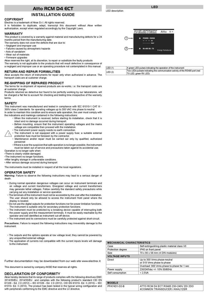
200 ÷ 240 VAC
5 6
1 2 3 4 8 9 10
12 3 4
20 19 18 17
11 12
12 11
The PLUS range of products are manufactured by Akse S.r.l. in compliance with
EMC 89/336/EEC regulations and in accordance with the following standards:
EMISSIONS = EN 50081-1 1992 EN5022 CLASS B, CISPR 22; IMMUNITY=
EN 50082-1 1992 (light industry) SAFETY=EN61010.
1 SAFETY
This instrument was manufactured and tested in compliance with class 2 IEC 1010 and VDE
411 standards, in accordance with group B VDE 0110 standards for operating voltages up to
250 VACrms phase to neutral. To maintain this condition and to ensure safe operation, the user
must comply with the indications and markings contained in the following instructions:
- when the instrument is received, before beginning installation, check that it is still intact and no
damage was incurred during the transport;
- before mounting, ensure that the operating voltage and mains voltage set are the same and then
proceed with the installation;
- the power supply does not require an earth connection;
- a 50 mA T fuse should be installed in the power supply circuit to the instrument;
- maintenance and/or repairs must be carried on only by qualified, authorized personnel;
- if there is ever the suspicion that safe use is no longer possible, the instrument must be discon-
nected and precautions must be taken against accidental use;
- operation is no longer safe when:
1) there are clearly visible damages;
2) the instrument no longer functions;
3) after a prolonged storage in unfavorable conditions;
4) after serious damages incurred during transport.
1.1 OPERATOR SAFETY
Read these pages carefully before installing and utilizing the instrument.
The instrument descibed in this user manual is intended for use by properly trained staff only.
Maintenance and/or repairs must be carried out by authorized personnel only. For proper, safe use
of the instrument and for maintenance and/or repair, it is essential that the persons instructed to
carry out these procedures follow normal safety precautions.
1.2 SYMBOLS
THIS SYMBOL MEANS: "READ THE INSTRUCTIONS"
2 POWER SUPPLY
ATTENTION:
The instrument must have a power supply with voltage ranging from 200÷240 VAC 50/60 Hz
using max. cable gauge 2.5 mm2 and attached to the power supply terminals (see Fig. below).
The instrument power supply does not need an earth connection. The instrument requires the
installation of an external 50 m AT type fuse in the power supply circuit.
2.1 CONNECTION OF THE VOLTAGE INPUT
Use cables with max. gauge 2,5 mm2and attach them to the screw terminals for voltage output.
The following drawings show how to connect the screw terminals to the phases. Refer to the
detailed wiring diagram to make the correct connection of the voltage input depending on the
selected instrument and on the plant it is installed into.
Rev. 06/01
Max 250 VAC
Phase-Neutral
2.2 CONNECTION OF THE CURRENT INPUT
The instruments are equipped with terminals for connection of the current signal inputs. Connect
cables as indicated in the following diagrams.
The P1 and P2 indications identify the current correct direction.
N.B.: In case the CT connection is accidentally reversed, the instrument provides an
automatic compensation and, hence, inputs will be correct.
Above feature applies to reversed voltage connection too.
It is, however, absolutely essential to follow the sequence of the phases between voltage and
current.
N.B. The secondary CT must always short circuit when it is not connected to the instrument
to avoid damages and risks to the operator.
3 INSTRUMENT PROGRAMMING
The writing "WAIT" appears when the instrument is powered. After a few seconds the measure-
ment will be displayed (the LED on the key is lighted).
The programming key is located at the bottom left corner of the front panel. To enter into
programming mode, press simultaneously the key and the key . On the display the
CT selection will appear:
Pressing the key the available CT ratio is selected (see diagram in the following page)
Once the selection has been operated, press the programming key to confirm/exit set up.
Pressing simultaneously the key and the key the kWh values are zeroed.Pressing
simultaneously the key and the key the kVArh values are zeroed.
The CT ratio prompted by default is 5/5.
Once the instrument has been programmed it is possible to disable the key by removing the
jumper placed near the current current inputs.
Once the jumper is removed it will not be possible to reset the counters and to change the CT ratio.
To enable again the programming functions, it is necessary to restore the jumper.
Remove the jumper for disabling set up and reset
3.1 ADDRESS OF THE INSTRUMENT (only for models 485/232)
After entering the programming page through and , press the key once more and
the address of the instrument will be displayed. The default address set by the manufacturer upon
delivery is:
.
It can be changed through: key to select the digit
Key to increase the digit
Key to decrease the digit
The flashing digit is active.
To exit the programming, press key a fourth time.
The maximum selectable number is 247.
AKSE S.r.l. via Aldo Moro, 39 - 42100 Reggio Emilia (RE) - Italy - Tel. +39.0522.924244 Fax. +39.0522.924245

PLUS PLUS-P
PLUS-485 PLUS 4-20mA
PLUS-232
English
L1
N
L3
L2
P2P1
S2S1 P2
S2S1
P1
P2
S2S1
P1
L1
N
L3
L2
P2P1
S2S1 P2
S2S1
P1
P2
S2S1
P1
8 9 101 2 3 4 5 6
20 19 18 17
RX
TX
8 9 10
1 2 3 4 5 6
20 19 18 17
A
B
5/5 500/5
25/5 600/5
40/5 750/5
50/5 800/5
60/5 1000/5
75/5 1200/5
80/5 1250/5
100/5 1500/5
120/5 1600/5
150/5 1800/5
200/5 2000/5
250/5 2500/5
300/5 3200/5
320/5 4000/5
400/5
5 TECHNICAL CHARACTERISTICS
Inputs: Voltage: 250V from 20 to 800 Hz
Current: 5 A from 20 to 800 Hz
Input overload: Voltage: max.264 Vrms phase to neutral
Current: max 20 Arms,
Number of scales: 2 current scales
1 current voltage
Size: Lenghth = 105 mm. (6 DIN modules)
Height = 90 mm.
Depth = 58 mm.
Weight: 315 g.
IP rating: Instrument = IP20
Front panel = IP40
Temperature range: from -10°C to +40°C
Relative humidity: R.H. max 90%
Condensation: not permitted
Isolation: in accordance with group B VDE 0110 standards
for 250 VACrms operating voltages.
Accuracy: Current ≤0.5% of the measurement
Voltage ≤0.5% of the reading
Power 1%
Energy consumption Class 2 according to IEC 1036
N.B. Do not espose the instrument display to the sunlight.
4 OPTIONAL CONNECTIONS
4.1 485 CONNECTION
4.2 RS232 CONNECTION
SELECTABLE CT RATIOS
Rev. 06/01
4.3 P CONNECTION
1Imp./kWh
Featuring pulse output for transmission of energy data. Each output is equivalent to 1kWh. The
output is a galvanically isolated OPTO MOS long life solid state relay rated at 250V, 100mA AC/
DC. The duration of the output pulse ranges between 400-500-mSec. ad recommended by
standards.
4.4 4-20mA CONNECTION
4-20mA
Galvanically isolated 4-20 mA output via 14-bit d/a converter. The output can handle load
impedances of up to 500 ohm. The 4-20mA output is proportional to active power.
8 9 10
1 2 3 4 5 6
20 19 18 17
8 9 10
1 2 3 4 5 6
20 19 18 17
+
_
AKSE S.r.l. via Aldo Moro, 39 - 42100 Reggio Emilia (RE) - Italy - Tel. +39.0522.924244 Fax. +39.0522.924245
This manual suits for next models
4
Other Electrex Protection Device manuals
