Girard Products WUD User manual

Owner’s
Manual
Winter Use Device:
W
U
D
For use only with GSWH-1
Helps Protect the GSWH-1
from
Freezing Temperatures
that may
cause damage to the
unit.
•
Installation
•
Operation
•
Service and
Maintenance
Installation and service must be
performed by a certified installer or
service agency.
The WUD
is certified for use with the
Girard Tankless Water Heater System
in RV’s
constructed for use where
freezing temperatures are likel
y
.
C
AUTION:
Read and Follow
all the Safety Rules
and Instructions.
Girard Products LLC
, 1361 Calle Avanazado, San Clemente CA 92673 U.S.A
Owner’s Manual Part No.1GWH9403
Patent Pending
P a g e
1

P
a
g
e
2
Winter Use Device
-
WUD
Installer/Customer Responsibilities
•
Read and observe all safety
rules
•
Keep these instructions and warranty for future
reference
•
If
this
device
is
purchased
as
an
aftermarket
item.
Installation
and
Ser
vice
must
be
performed
b
y
a
certified
installer
or
ser
vice
a
gency
.
•
Do not attempt installation
as a
Do-it-Yourself
project
•
Follow all applicable State and Local
Codes
This is the safety alert symbol.
It
is used to alert you to potential
personal injury hazards. Obey all safety messages that
follow
this symbol to avoid possible injury or death. Failure to
follow
these alerts could result in Fire, Explosion or even Death.
WARNING
–
FIRE OR EXPLOSION
WARNING: These instructions must be followed exactly, or a fire or
explosion
may result causing property damage, personal injury or death
.
•
Do
not
store
or
use
gasoline
or
other
flammable
va
pors
and
liquids
in
the
vicinity
of
this or any other
appliance.
•
FOR YOUR SAFETY
-
WHAT TO DO IF YOU SMELL
GAS
•
DO NOT
attempt to light any
appliance.
•
DO NOT
touch any electrical switch, or
use
any phone or radio in the
vehicle.
•
DO NOT
start the vehicle’s engine or electric genera
tor
.
•
Evacuate all persons from the
vehicle.
•
Shut off the
gas
supply
at
the
gas
container or
source.
•
Contact the nearest certified service technician or
gas
supplier for
repairs.
•
If
you cannot reach
a
certified service technician or
gas
supplier, contact
the
nearest fire
department.
•
DO NOT
turn on the
gas
supply until the
gas
leak(s)
has
been
repaired.
•
Installation and service must
be
performed by
a
qualified installer or service
agency.

P
a
g
e
3
WARNING! PRODUCT DAMAGE
•
Freezing
of
the
internal
pipes
and
Heat
Exchanger
of
the
Model
GSWH-1
wa
ter
heater
will
result
in
severe
damage
not
covered
b
y
warranty
.
For
this
reason
it
is
not
advisable
to
use
the
GSWH-1
in
the
winter
unless
the
RV
is
manufactured
f
or
use
in
the
winter
and
equipped
with
the
Winter
Use Device. Consult your OEM and or dealer for additional inf
ormation.
CRITICAL INSTALLATION
W
ARNINGS
•
Installation
and
ser
vice
must
be
performed
b
y
a
qualified
installer
or
ser
vice
a
gency
.
This product is not designed for Do-it-Yourself
Installation.
•
Install
ONL
Y
in
recrea
tion
vehicles
(RV’
s)
tha
t
are
manufactured
and
properl
y
insula
ted
f
or
use
in
areas
where
the
risk
of
freezing
temperatures
are
likel
y
.
RV’
s
are
recrea
tion
vehicles
designed
as
temporar
y
living
quarters
f
or
recrea
tion,
camping,
or
tra
vel
use
ha
ving
their
own power or towed by another vehicle. This Winter Use Device is
NOT
designed for use
with any other appliance or
product.
•
DO NOT
modify
the Winter Use Device in any way. This is dangerous and
will void the
warranty.
USA AND CANADA
-
FOLLOW ALL APPLICABLE STATE AND LOCAL CODES
IN THE ABSENCE OF LOCAL CODES OR REGULATIONS REFER TO CURRENT
STANDARDS OF:
•
Recreational
V
ehicles
ANSI
A119.2/NFP
A
501C.
•
CSA
standard Z240
RV
Series, Recreational
V
ehicle.
•
Park Trailers
A119.5
•
National Fuel Gas Code ANSI
Z223.1 and/or
CAN/CGA
B149 Installation
Codes
•
Federal
Mobile
Home
Construction
&
Safety
Standard,
T
itle
24
CFR,
part
3280,
or
when
this
Standard
is
not
a
pplicable,
the
Standard
f
or
Manufactured
Home
Installations
(Manufactured
Home
Sites,
Communities
and
Set-Ups),
ANSI
A255.1
and/or
CAN/
CSA-Z240 MHSeries, Mobile
Homes.
•
National Electrical Code ANSI/NFPA No.
70
and/or CSA
C22.1

P
a
g
e
4
IMPOR
TANT!
•
For
proper
opera
tion,
the
GSWH-1
wa
ter
heater
requires
a
minimum
wa
ter
flow
of
1.0
Gallon
per Minute (gpm) for each Hot Water faucet it
supplies.
WINTER USE DEVICE
(WUD)
Description
Girard
Products
LLC
of
fers
a
Winter
Use
Device
(
WUD
-
P
art#
1GWHAF
)
as
an
option
f
or
use
with
the GSWH-1.The Winter Use Device helps protect the GSWH-1 water heater when freezing
conditions
are likely to occur by automatically activating the GSWH-1 for
a
short period of
time.
This is know
as
the Anti-Freezing
Mode.
Anti-freezing Mode
T
o
prevent
freezing
of
the
wa
ter
in
the
wa
ter
heater
itself,
the
WUD
utilizes
a
Thermostat
and
a
12VDC
solenoid valve to create
a
demand for hot water whenever the ambient temperature falls
below 38°F. This will
cause the unit to automatically light for
a
short period of time IF
the GSWH-1
SWITCH
is set to the
‘ON’
position,
the system is
POWERED
with 12VDC (the
PUMP
must
be
ON
),
GAS
is available and
FRESH WATER
from the holding tank is provided to the water
heater.
Upon
reaching
a
temperature of approximately
50°
F the unit will
automatically shut off and return to
a
stand by
condition.
IMPOR
TANT!
•
The
Anti-freezing
Mode
function
of
the
WUD
is
designed
to
prevent
onl
y
the
wa
ter
in
the
GSWH-1
internal water heater pipes from freezing,
NOT
the entire plumbing system of the
RV
.
IMPOR
TANT!
The
Winter Use Device
will work only
when:
•
The RV can provide
a
sufficient supply of fresh
water.
•
The water heater is adequately powered
with
12VDC
and switched
ON
.
•
The RV
Water pump is switched
ON
and is working
properl
y
.
•
There
is
sufficient
LP
Gas
in
the
LP
tank
f
or
the
wa
ter
heater
to
operate
and
the
gas
system
is
turned
ON
.

5
IMPOR
TANT!
•
The
Winter
Use
Device
warranty
is
conditional
on
proper
use.
Provided
tha
t
all
the
a
bove
conditions
are
met,
an
y
a
pplicable
warranty
replacement
and/or
repairs
are
limited
to
the
Girard
T
ankless
W
a
ter
Hea
ter
system
and
no
other
part
of
the
plumbing
or
other
RV
subsystems.
•
All
models of the Girard GSWH-1 Tankless Water Heater (with or without the
Winter Use
Device
)
must
be
winterized if the
RV is not in
use
and/or in
storage.
C. Components
The
WUD
device consists of
two components:
1)
a
Thermostat
and
2)
a
Solenoid
1. Thermostat
A
thermosta
t
mounted
on
the
Heat
Exchanger
of
the
wa
ter
heater
(Figure
1)
and
connected
internall
y
to the 12VDC power. The power connection is made after the
Power ON/OFF
switch located on
the GSW-1; NOTE:
power is
NOT
supplied unless the switch is in the
ON
position.
.
Figure
1
The output of the thermostat is provided at the electrical connections on the
back of the water heater (Orange wire) to provide power to the Solenoid valve
as needed (Figure
2).

6
Figure
2
2. Solenoid
V
alve
.
The Solenoid
V
alve
may
be
located in either of two locations:
Option 1:
attached to the Hot Wa
ter
Outlet on the back of the Water Heater (recommended) and plumbed both to the
Hot Water
System
AND
the
fresh
wa
ter
tank;
or
Option
2
:
somewhere
between
the
W
a
ter
Hea
ter
and
the
Fresh
Water Tank and plumbed to the system and the fresh water
tank.
Regardless of location, it
must
be
plumped properly to function correctly. Consult your OEM for the location if installed
at
time of
production.
Note:
In
certain aftermarket installations access to the fresh water tank may not
be
possible. The solenoid out water line
can
be
connected to
a
drain or routed to the ground but
be
aware that
a
patch of ice may form under the
RV
which may cause
a
hazardous
condition.
CRITICAL INSTALLATION
W
ARNING!
•
The
Solenoid
V
alve
must
be
loca
ted
where
it
is
easil
y
accessible
should
ser
vice
be
required.
Girard will not
be
responsible for labor charges to locate and make
accessible.

7
Figure
3
PEX
tubing and connector may be used for the installation of the Solenoid
V
alve.
INSTALLATION, OPERATION, MAINTENANCE AND SERVICE
WARNING! PRODUCT DAMAGE!
•
Freezing
of
the
internal
pipes
and
Heat
Exchanger
of
the
Model
GSWH-1
wa
ter
heater
will
result
in
severe
damage
not
covered
b
y
warranty
.
For
this
reason
it
is
not
advisable
to
use
the
unit
in
the
winter
unless
the
RV
is
manufactured
f
or
use
in
the
winter
and
equipped
with
this
option. Consult your OEM for additional inf
ormation.
WARNING!
C
AUTION!
•
Improper
installation,
adjustment,
altera
tion,
ser
vice
or
maintenance
can
cause
property
damage,
personal
injur
y
or
loss
of
life
•
Installation and service must
be
performed by
a
qualified installer, service
agency
•
This product is NOT designed nor intended for Do-it-Yourself
Installation.

8
INST
ALLATION
CRITICAL INSTALLATION
W
ARNINGS!
•
Installation
and
ser
vice
must
be
performed
b
y
a
qualified
installer
or
ser
vice
a
gency
.
This
product is not designed for Do-it-Yourself
Installation.
•
Install
ONL
Y
in
recrea
tion
vehicles
(RV’
s)
tha
t
are
manufactured
and
insula
ted
f
or
use
in
areas
where
the
risk
of
freezing
temperatures
is
likel
y
.
RV’
s
are
recrea
tion
vehicles
designed
as
temporar
y
living
quarters
f
or
recrea
tion,
camping,
or
tra
vel
use
ha
ving
their
own
power
or
towed by another vehicle. The Winter Use Device is
NOT
designed for any use with any other
appliance or
product.
•
DO NOT
modify
the Winter Use Device in any way. This is dangerous and
will void the
warranty.
The following instructions apply to the most common type of installation for Girard Products Winter
Use Device. Consult with Girard Products,
LLC
technical support or engineering department
if you
have any additional questions regarding your specific
installation/application.
Plumbing Installations
CRITICAL INSTALLATION
W
ARNINGS!
•
The
Solenoid
V
alve
must
be
loca
ted
where
it
is
easil
y
accessible
should
ser
vice
be
required. Girard
will not
be
responsible for labor charges to locate and make
accessible.
1.
Select
a
suita
ble
location
(Figure
5.)
to
install
the
Solenoid
V
alve,
close
to
the
GSWH-1
and
to
12V
power
wires.
2.
Locate the
HOT
water line closest to this loca
tion.
3.
Insert
a
Tee in the line and connect
a
hot water line extension to the selected
location.
4.
Insert
a
T
ee
to
the
fresh
water
tank
and
connect
the
“OUT”
port
of
the
Solenoid
V
alve
to
the
side
port.
5.
Connect the hot water line extension to the
“IN”
port of the Solenoid
V
alve.
6.
Check for
leaks
Note:
In
certain
aftermarket
installations
access
to
the
fresh
water
tank
ma
y
not
be
possible.
The
solenoid
out
water
line
can
be
connected
to
a
drain
or
routed
to
the
ground
but
be
a
ware
that
a
patch
of
ice
ma
y
f
orm
under
the
RV
which
ma
y
cause a hazardous
condition.

9
B.
Electrical
The wiring of the solenoid valve may be carried out with either 16AWG or 18AWG
wires. Simply
bring an extension of the
orange
wire from the
Water heater to the location of the Solenoi
d
Valve
and connect to the
RED
wire on the Solenoid Valve. The current draw of the valve at
12
VDC
is
less than 350mA.
-
12V
or
Mode SW
Cold
Hot
Hl-lo Gromd
Row
SWitch
w
u
o
Heat
Exchanger
ECO
Gas
Valve
12VDC (Red)
-
-12VDC
Ground
(
Black
)
--
Ground
(Green)
-
Gas Valve (Brown)
•••••••
LED
(Diagnostics)
•u••••
12VDC Row
I
Limi
t
I
Air
Figure
10

10
Operation
Anti-freezing Mode
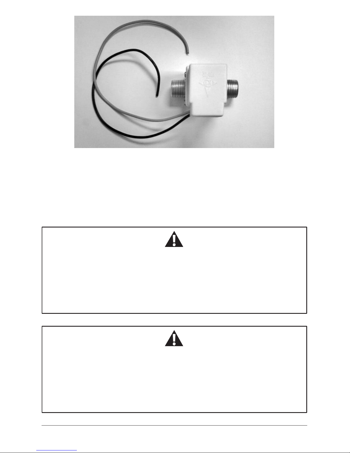
The operation of the Anti-Freezing Mode in the
Winter Use Device (WUD)
is
TOTALLY
AUTOMATIC
, IF the
GSWH-1 SWITCH
is set to the
‘
ON
’
position,the system is
POWERED
with
12VDC (the
PUMP
must
be
ON
),
GAS
is available i.e., turned
ON
, and
FRESH WATER
from the
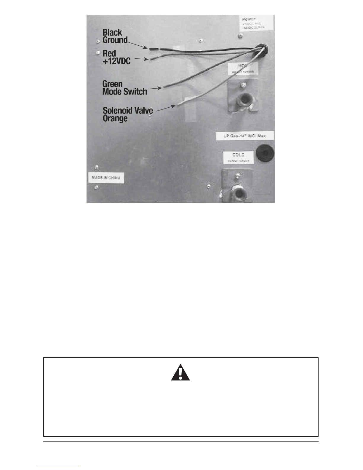
holding tank is provided to the water heater. Whenever the temperature of the thermostat mounted on
the Heat Exchanger reaches
a
temperature of 38°F, the thermostat
will
close and the Solenoid valve
powered through the Orange wire
will
open.
This creates
a
demand for water which
will
cause
the
Water Heater to start. The Water Heater will
operate until the thermostat reaches
a
temperature
over
50
°F when it will
open, causing the Solenoid
V
alve
to close and the Water Heater to shut off.
T
ypicall
y
the Water Heater will
run for approximately
45 seconds.
NOTICE!
•
The RV can provide
a
sufficient supply of fresh
water.
•
The water heater is adequately powered with 12VDC; and switched
ON
.
•
The RV
Water pump is switched
ON
and is working
properl
y
.
•
There
is
sufficient
LP
Gas
in
the
LP
tank
f
or
the
wa
ter
heater
to
operate
and
the
gas
system
is
turned
ON.
Maintenance
Nospecial maintenance of the
WUD
components is required.
If
you wish to add the Winter Use Device to your unit (Part#1GWH) please consult
with
your RV manufacturer to ensure your RV is properly insulated and designed for winter use.
Girard Products Winter Use Device warranty is conditional on proper use. Provided
that
all the conditions above are met, any applicable warranty replacement and/or repairs
are
limited to the Girard Tankless Water Heater and no other part of the plumbing or other RV
subsystem.
All
models
of
the
Girard
T
ankless
W
a
ter
Hea
ter
(with
or
without
the
Winter
Use
Device
must
be
winterized if the
RV is not in
use
and/or in
stora
ge).

Manuel de l’utilisateur
Dispositif d’utilisation hivernale
DUH
À utiliser uniquement avec
le modèle GSWH-1
Aide à protéger le chauffe-eau GSWH-1
contre les dommages causes par les
températures hivernales.
•
Installation
•
Utilisation
•
Service
et entretien
L’installation et l’entretien doivent
être effectués par une agence de
service ou un installateur qualifié.
Le DUH
est certifié pour une
utilisation avec le système de
chauffe-eau sans réservoir de Girard
conçu pour être utilisé où il y a des
risques de températures hivernales.
ATTENTION :
Lire
et
respecter
toutes
les règles
desécurité
et les instructions
Girard Products LLC
, 1361 Calle Avanazado, San Clemente CA 92673 U.S.A
Manuel
de
partie Numéro 1GWH9406 propriétaire
du
Brevet
eninstance
P a g e
11

12
Dispositif d’utilisation hivernale
-
DUH
Responsabilités de
l’installateur/client
•
L
’installation
et
l’entretien
doivent
être
ef
fectués
par
un
installa
teur
,
une
a
gence
de
ser
vice
ou
un
f
ournisseur
de
gaz
recommandé
par
Girard
Products
LLC.
•
Ne
pas
tenter d’installer l’appareil
soi-même.
•
Lire
et
respecter toutes les règles
desécurité.
•
Lors du réapprovisionnement
en
carburant, éteindre les appareils
à
gaz
et
les flammes
pilotes.
•
Conserver
ces
instructions
et
la
garantie
pour
consultation
future.
•
Respecter
tous
les
codes
fédéraux
et
locaux.
Si
cet
a
ppareil
est
acheté
sur
le
marché
secondaire,
l’installa
tion
et
le
ser
vice
doivent
être
ef
fectués
par
une
a
gence
de
ser
vice
ou
un
installateur qualifié.
Il
s’agit du symbole d’alerte de sécurité.
Il
est utilisé pour
signaler les dangers de blessure possibles. Respecter tous les
messages de sécurité qui suivent ce symbole pour éviter des
blessures potentielles ou la mort. Le manquement à ces alertes
peut causer en un incendie, une explosion ou même la
mort.
AVERTISSEMENT
–
INCENDIE OU EXPLOSION
AVERTISSEMENT :
Ne pas respecter ces instructions risque d’entraîner un incendie
ou une explosion et des dégâts matériels, des blessures ou la
mort.
•
Ne
pas
entreposer
ni
utiliser
d’essence
ni
autres
va
peurs
et
liquides
inflamma
bles
à
proximité
de
cet appareil ou
de
tout autre
appareil.
•
SÉCURITÉ
-
QUE FAIRE EN PRÉSENCE D’UNE ODEUR DE GAZ
•
NE PAS
tenter d’allumer tout
appareil.
•
ÉVITER
de
toucher
à
tout
interrupteur
électrique
et
NE
PAS
utiliser
de
téléphone
ou
de
radio dans le
véhicule.
•
NE PAS
démarrer le véhicule ou le générateur
électrique.
•
Évacuer
TOUS
les passagers du
véhicule.
•
Couper l’alimentation
en
gaz
au
niveau du réservoir ou
à
la
source.
•
Communiquer
a
vec
le
f
ournisseur
de
gaz
ou
le
technicien
d’entretien
qualifié
le
plus
près
pour effectuer toute
réparation.
•
S’il
est
impossible
de
joindre
un
f
ournisseur
de
gaz
ou
un
technicien
d’entretien
qualifié,
communiquer avec le service
des
incendies le plus
près.
•
NE PAS
ouvrir l’alimentation
en
gaz avant que la ou les fuites soient
réparées.
•
L
’installation
et
l’entretien
doivent
être
ef
fectués
par
une
a
gence
de
ser
vice
ou
un
installa
teur
qualifié.

13
AVERTISSEMENT! DOMMAGES AU PRODUIT
•
Le
gel
des
tuyaux
internes
et
de
l’échangeur
de
chaleur
du
chauf
fe-eau
modèle
GSWH-1
causera
d’importants
domma
ges
non
couverts
par
la
garantie.
Pour
cette
raison,
il
n’est
pas
recommandé
d’utiliser
le
modèle
GSWH-1
en
hiver
à
moins
que
le
VR
soit
conçu
pour
l’utilisa
tion
hivernale
et
équipé
d’un
dispositif
d’utilisation
hivernale.
Consulter
votre
fabricant
d’équipement ou votre détaillant pour obtenir
de
plus amples
renseignements.
AVERTISSEMENTS IMPORTANTS
D’INST
ALLATION
•
L
’installation
et
l’entretien
doivent
être
ef
fectués
par
une
a
gence
de
ser
vice
ou
un
installa
teur
qualifié. Ce produit n’est
pas
conçu pour une installation par
soi-même.
•
Installer
SEULEMENT
dans
un
véhicule
récréa
tif
(VR)
qui
a
été
fabriqué
et
correctement
isolé
pour
une
utilisation
où
il
y
a
des
risques
de
température
hivernale.
Les
VR
sont
des
véhicules
récréa
tifs
conçus
comme
résidence
temporaire
pour
les
vacances,
le
camping
ou
les
voya
ges;
ils
peuvent
être
autopropulsés
ou
remorqués
par
un
autre
véhicule.
Ce
dispositif
d’utilisation hivernale N’est PAS conçu pour être utilisé avec tout autre appareil ou
produit.
•
NE
PAS
modifier
le
dispositif
d’utilisation
hivernale
de
quelque
façon
que
ce
soit.
Cela
est
dangereux
et
invalidera la
garantie.
É.-U. d’A. ET CANADA
-
RESPECTER TOUS LES CODES NATIONAUX ET
LOC
AUX.
À DÉFAUT RÉGLEMENTATIONS OU DE CODES LOCAUX, CONSULTER LES
NORMES
ACTUELLES DE :
•
Véhicules
récréa
tifs
ANSI
A119.2/NFP
A
501C.
•
Norme CSA Z240 VC,
Véhicules
decamping.
•
Cara
vanes
de
parc
A119.5.
•
Code
na
tional
de
carburant
et
de
gaz
ANSI
Z223.1
et/ou
codes
d’installation
CAN/CGA
B149.
•
Norme
fédérale
de
sécurité
et
de
construction
de
maisons
mobiles,
titre
24
CFR,
partie
3280
;
lorsque
cette
norme
n’est
pas
a
pplicable,
utiliser
la
norme
d’installation
de
maisons
préfa
briquées
(Sites
de
maisons
préfa
briquées,
collectivités
et
installa
tion),
ANSI
A255.1
et/ou
la
série
CAN/CSA-Z240
MH,
maisons
mobiles.
•
Code
électrique
na
tional
ANSI/NFP
A
N°
70
et/ou
CSA
C22.1.

14
IMPOR
TANT!
•
Pour
assurer
un
bon
f
onctionnement
du
chauf
fe-eau
GSWH-1,
celui-ci
requiert
un
débit
d’eau
minimum
de1,0
gallon par minute (gpm) pour chaque robinet d’eau qu’il
alimente.
Dispositif d’utilisation hivernale (DUH)
Description
Girard Products
LLC
offre un dispositif d’utilisation hivernale
(DUH
-
pièce
n°
GWHAF)
comme
une option
à
utiliser avec le modèle GSWH-1.Le dispositif d’utilisation hivernale aide
à protéger
le
chauf
fe-eau
GSWH-1
lorsqu’il
y
a
des
risques
de
températures
hivernales
en
mettant
automa
tiquement
en
marche
le
GSWH-1
pour
une
courte
période.
Cette
f
onction
est a
ppelée
Mode
antigel.
Mode antigel
Pour prévenir le gel
de
l’eau dans le chauffe-eau lui-même, le
DUH
utilise un thermostat
et une
vanne électromagnétique 12V CC pour créer une demande d’eau chaude lorsque la
température
ambiante
est
inférieure
à 38
°F/3 °C. Ainsi,l’unité s’allumera automatiquement pour une
courte
période
SI l’INTERRUPTEUR
du modèle GSWH-1
est à
la position « ON » (En marche), si le
système
est
ALIMENTÉ
en
courant
continu
12V
(la
pompe
doit
être
allumée),
s’il
y
a
du
GAZ
et
si
le
réser
voir
d’EA
U
FRAÎCHE
f
ournit
de
l’eau
au
chauf
fe-eau.
Lorsque
la
température
a
tteint
environ
50
°F/10
°C,
l’unité
se
fermera automatiquement
et se
remettra
en
mode attente. stand by
condition.
IMPOR
TANT!
•
La
f
onction
antigel
du
DUH
est
conçue
pour
prévenir
uniquement
le
gel
de
l’eau
qui
se
trouve
dans les tuyaux internes du chauffe-eau
et
NON dans toute la plomberie du VR.
A
VIS!
Le dispositif d’utilisation hivernale fonctionnera seulement quand
:
•
Le VR
peut fournir un approvisionnement suffisant
en
eau
courante.
•
Le
chauf
fe-eau
est
adéquatement
alimenté
par
du
courant
12
V
CD
et
que
l’interrupteur
est à
la position En
marche.
•
La pompe
à
eau du VR
est en
marche
et
fonctionne
bien.
•
Il
y
a
suffisamment
de
gaz
propane
liquide
dans
le
réser
voir
de
gaz
propane
liquide
pour
faire
fonctionner le chauffe-eau
et
le système
au
gaz
est en marche.

15
A
VIS!
•
La
garantie
du
dispositif
d’utilisation
hivernale
est
conditionnelle
à
la
bonne
utilisation.
Si
toutes
les
conditions
ci-dessus
sont
respectées,
toute
garantie
de
remplacement
et/ou
de
répara
tion
est
limitée
au
système
de
chauf
fe-eau
sans
réser
voir
de
Girard
et
à
aucune
autre
partie
de
la plomberie ni partie
des
sous-systèmes du VR.
•
Il
faut
procéder
à
l’hiverna
ge
de
tous
les
modèles
de
chauf
fe-eau
sans
réser
voir
GSWH-1
de
Girard
(avec
ou
sans
dispositif
d’utilisation
hivernale
)
si
le
VR
n’est
pas
utilize
ou
s’il
est
entreposé.
C. Composantes
Le DUH
comporte deux
composantes:
1) un thermostat
et
2) une valve électromagnétique
1.Thermostat.
Un thermostat
installé sur l’échangeur
de
chaleur du chauffe-eau (Figure 1)
et
branché
à
l’alimentation 12V CC interne. La connexion électrique
est
faite lors
l’interrupteur situé sur
le
modèle est à la position ON
(En marche).
NOTE:
Il N’y a
PAS
de
courant si l’interrupteur
n’est
pasà
la position
ON
(En
marche).
.
Figure
1
La sortie du thermostat se trouve parmi les connexions électriques
à l’arrière du chauffe-eau (fil orange) pour alimenter la vanne
électromagnétique au besoin (Figure
2).

16
Figure
2
2. Vanne électromagnétique
La
vanne
électromagnétique
peut
être
située
à
deux
endroits:
Option
1
:
(recommandée)
Elle
peut
être
fixée
à
la
sortie
d’eau
chaude
à
l’arrière
du
chauf
fe-eau
et
raccordée
au
système
d’eau
chaude
ET
au
réser
voir
d’eau
fraîche;
Option
2:
Quelque part entre le chauffe-eau
et
le réservoir d’eau fraîche
et
raccordée
ausystème
et au
réservoir d’eau fraîche. Peu importe l’endroit,elle doit être raccordée correctement pour
bien
fonctionner. Consultez votre fabricant d’équipement pour connaître l’endroit si elle
est
installée
au
moment
de
la
fabrication.
Remarque :
Dans certaines pièces
de
rechange installations accès dans le réservoir d’eau douce
ne
serait possible. Le
solénoïde hors ligne d’eau peut être relié
à
un drain ou acheminée vers le sol mais être conscient qu’une plaque
de
glace
peut
se
former dans le cadre
de
la RV
qui peut causer une
dangereuse.
AVERTISSEMENT IMPORTANT
D’INST
ALLATION
•
Si
l’option
2 est
choisie,
la
vanne
électromagnétique
doit
être
située
où
elle
est
facilement
accessible
si
elle
doit
être
réparée.
Girard
ne
sera
pas
responsa
ble
des
frais
de
main-d’œuvre
pour trouver la vanne
et
la rendre
accessible.

17
Figure
3
Un tuyau et un raccord en polyéthylène réticulé peuvent servir à l’installation de la vanne électroma
gnétique.
INSTALLATION, UTILISATION, ENTRETIEN ET
MAIN-D’ŒUVRE
AVERTISSEMENT! DOMMAGES AU PRODUIT
•
Le
gel
des
tuyaux
internes
et
de
l’échangeur
de
chaleur
du
chauf
fe-eau
modèle
GSWH-1
causera
d’importants
domma
ges
non
couverts
par
la
garantie.
Pour
cette
raison,
il
n’est
pas
recommandé
d’utiliser
l’unité
en
hiver
à
moins
que
le
VR
soit
conçu
pour
l’utilisa
tion
hivernale
et
équipé
de
ce
dispositif.
Consulter
votre
fabricant
d’équipement
pour
obtenir
de
plus
amples
renseignements.
AVERTISSEMENT! ATTENTION!
•
L
’installation,
le
régla
ge,
la
modification,
la
répara
tion
ou
l’entretien
incorrect
de
cet
a
ppareil
peut
causer
des
domma
ges
ma
tériels,
des
blessures
ou
la
mort.
•
L
’installation
et
l’entretien
doivent
être
ef
fectués
par
un
installa
teur
,
une
a
gence
de
ser
vice
ou
un fournisseur
de
gaz recommandé par Girard Products LLC.
•
Ce produit n’est
pas
conçu pour être installé par
l’acheteur.

18
INST
ALLATION
AVERTISSEMENTS IMPORTANTS
D’INST
ALLATION!
•
L
’installation
et
l’entretien
doivent
être
ef
fectués
par
une
a
gence
de
ser
vice
ou
un
installa
teur
qualifié. Ce produit n’est
pas
conçu pour une installation par
soi-même.
•
Installer
SEULEMENT
dans
un
véhicule
récréa
tif
(VR)
qui
a
été
fabriqué
et
correctement
isolé
pour
une
utilisation
où
il
y
a
des
risques
de
température
hivernale.
Les
VR
sont
des
véhicules
récréa
tifs
conçus
comme
résidence
temporaire
pour
les
vacances,
le
camping
ou
les
voya
ges;
ils
peuvent
être
autopropulsés
ou
remorqués
par
un
autre
véhicule.
Le
dispositif
d’utilisation
hivernale N’est PAS conçu pour être utilisé avec tout autre appareil ou
produit.
•
NE
P
AS
modifier
le
dispositif
d’utilisation
hivernale
de
quelque
façon
que
ce
soit.
Cela
est
dangereux
et
invalidera la
garantie.
Les instructions suivantes s’appliquent
au
type d’installation le plus commun du dispositif d’utilisation
hivernale
de
Girard Products. Consulter le service
de
soutien technique ou d’ingénierie
de
Girard
Products,
LLC
pour les questions concernant l’installation
de
l’a
ppareil.
Installation de la plomberie
AVERTISSEMENT IMPORTANT
D’INST
ALLATION
•
La
vanne
électromagnétique
doit
être
située
où
elle
est
facilement
accessible
si
elle
doit
être
réparée.
Girard
ne
sera
pas
responsa
ble
des
frais
de
main-d’œuvre
pour
trouver
la
vanne
et
la
rendre
accessible.
1.
Choisir
un
emplacement
adéqua
t
(Figure
5)
pour
l’installa
tion
de
la
vanne
électroma
gnétique,
près
du
GSWH-1
et
les fils d’alimentation 12V.
2.
Trouver la conduite d’eau
CHAUDE la plus près
de
cet
endroit.
3.
Insérer
un
T
dans
la
conduite
et
raccorder
une
rallonge
de
conduite
d’eau
chaude
vers
l’endroit
choisi.
4.
Insérer
un
T
dans
le
réser
voir
d’eau
fraîche
et
raccorder
le
port
de
«
SOR
TIE
»
de
la
vanne
électromagnétique ou port
latéral.
5.
Raccorder
la
rallonge
de
conduite
d’eau
chaude
au
port
d’«
ENTRÉE
»
de
la
vanne
électromagnétique.
6.
Vérifier s’il y
a desfuites
Remarque
:
Dans
certaines
pièces
de
rechange
installations
accès
dans
le
réser
voir
d’eau
douce
ne
serait
possible.
Le
solénoïde
hors
ligne
d’eau
peut
être
relié
à
un
drain
ou
acheminée
vers
le
sol
mais
être
conscient
qu’une
plaque
de
glace peut
se
former dans le cadre
de
la RV
qui peut causer une
dangereuse.

19
B.ElectriciM
Le
cablage de
Iavanne electromagnetique doit
comporter des fils de
calibre
16
AWG
ou 18
AWG.Apporter simplement
une
rallonge du filorange
du
chauffe·eau
a
l'endroit de
Ia
vanne
electromagnetique et raccorder le
fil
ROUGE
a
Iavanne electromagnetique.
La
charge
de
courant de
Ia
vanne
a
t
'N
CC est
moins
de
350
mA.
Diagramm11
d11
cJblag11
du
OlJH
+12V31avanne
·12V
ou
-12
v
mise
a
Ia
ll!m!
ln1etrupll!ur
de
geurd'air
••••••••••••••....
ECO
haculllon
12
V
CC
(rouge)
---
-12
V
CC
mise*
Iaterre
(noll)
--
Mise* Ia
terre
(vert)
---
Vanne
de
gaz
(brun)
•••••••
DEL
(dlagnGStlcs)
Vanne de
gaz
•
......
12
V CC Debit
/limite
I
Air
Agu-e
10

20
Fonctionnement
Mode
antigel
L’utilisation du mode antigel dans le dispositif d’utilisation hivernale
(DUH)
est
COMPLÈTEMENT
AUTOMATIQUE, SI l’INTERRUPTEUR GSWH-1
est à
la position « ON » (En marche), le
système
est
ALIMENTÉ
avec
du
courant
continu
12
V
(la
pompe
doit
être
en
marche),
le
GAZ
disponible,
ouvert,
et
le chauffe-eau doit être alimenté
en
eau fraîche par le chauffe-eau. Lorsque la
température
du thermostat installé sur l’échangeur
de
chaleur atteint
38
°F/3 °C, le
se
fermera
et
la
vanne
électromagnétique alimentée par le
fil
orange d’ouvrira. Cela créera une demande d’eau qui
fera
démarrer
le
chauf
fe-eau.
Le
chauf
fe-eau
f
onctionnera
jusqu’à
ce
que
la
température
a
tteigne50
°F/10 °C
à ce
moment la vanne électromagnétique
se
fermera
et
le chauffe-eau
s’éteindra.
Généralement, le chauffe-eau fonctionnera environ
45 secondes.
A
VIS!
Le dispositif d’utilisation hivernale fonctionnera seulement quand
:
•
Le VR
peut fournir un approvisionnement suffisant
en
eau
courante.
•
Le
chauf
fe-eau
est
adéquatement
alimenté
par
du
courant
12V
CC
et
que
l’interrupteur
est à
la position En
marche.
•
La pompe
à
eau du VR
est en
marche
et
fonctionne
bien.
•
Il
y
a
suffisamment
de
gaz
propane
liquide
dans
le
réser
voir
de
gaz
propane
liquide
pour
faire
fonctionner le chauffe-eau
et
le système
au
gaz
est en marche.
Entretien
Les composantes du
DUH
ne
nécessitent aucun entretien
particulier.
Si vous souhaitez ajouter un dispositif d’utilisation hivernale à votre unité (n° de pièce
1GWH), consultez votre fabricant de VR pour vous assurer que votre VR est suffisamment
isolé et conçu pour être utilisé dans des conditions hivernales.
La garantie du dispositif d’utilisation hivernale de Girard Products est conditionnelle
à
la bonne utilisation du produit. Si toutes les conditions ci-dessus sont respectées, toute
garantie de remplacement et/ou de réparation est limitée au système de chauffe-eau sans
réservoir de Girard et à aucune autre partie de la plomberie ni partie des sous-systèmes
du VR.
Il
faut
procéder
à
l’hiverna
ge
de
tous
les
modèles
de
chauf
fe-eau
sans
réser
voir
de
Girard
(avec
ou
sans
dispositif d’utilisation hivernale
)
si le VR n’est
pas
utilisé ou qu’il
est entreposé.
Other manuals for WUD
1
Table of contents
Languages:
Other Girard Products Protection Device manuals
Popular Protection Device manuals by other brands

GE
GE Multilin 3 Series Guide

Wayne-Dalton
Wayne-Dalton FireStar 540 installation instructions

Palmer Safety
Palmer Safety ANCHOR2WAYSEAM instruction manual

Siemens
Siemens SIPROTEC 4 7VK61 manual

Cardin Elettronica
Cardin Elettronica SEL Series quick start guide

ASCO POWER TECHNOLOGIES
ASCO POWER TECHNOLOGIES 450 Installation & operation manual