Electrolab RediLevel 2100 DLS User manual

EL 29306 © 2022 Electrolab, Inc. All Rights Reserved.
USER MANUAL
MODEL 2100 DLS PRODUCT LINE
REDILEVEL 2100 DLS

RediLevel 2100 DLS page ii
EL 29306 © 2022 Electrolab, Inc. All Rights
Reserved.
© 2022 Electrolab, Inc.ALL RIGHTS RESERVED.
This document may not be reproduced, copied (except for a single archive copy), used, disclosed,
transferred (including sold, leased, or rented) adapted or modified except in accordance with the terms
andconditions of the License Agreement between the user and Electrolab, Inc.
Electrolab, Inc. makes no representations of warranties with respect to the contents hereof and
specificallydisclaims any implied warranties of merchantability of fitness for any particular purpose.
Electrolab, Inc. reserves the right to revise this publication and to make changes from time to time in
its content without the obligation to notify any person or organization of such revision or changes.

RediLevel 2100 DLS page iii
EL 29306 © 2022 Electrolab, Inc. All Rights
Reserved.
Table of Contents
Description ....................................................................................................................................................... 1
Communications............................................................................................................................................... 1
Wiring Connections .......................................................................................................................................... 1
Installation........................................................................................................................................................ 1
Sensor Calibration Procedure - Setting the Initial Offset ................................................................................. 2
Procedure: ........................................................................................................................................................ 2
Testing and Troubleshooting............................................................................................................................ 3
Digital Level Sensor Protocol............................................................................................................................ 3
Command syntax.............................................................................................................................................. 3
Data Request Commands................................................................................................................................. 4
Report Level and Temperature ........................................................................................................................ 4
Report Level and Temperature Continuously (factory diagnostics) ................................................................ 5
Report 4-20mA Output Level (version 3.09 and higher) .................................................................................. 5
Report Temperature Only ................................................................................................................................ 5
Configuration Commands................................................................................................................................. 5
Assign Unit Number ......................................................................................................................................... 5
Assign Unit Number to Sensor With the Corresponding Serial Number (version 3.15 and higher) ................ 6
Set Baud Rate ................................................................................................................................................... 6
Set Number of Floats........................................................................................................................................ 6
Set Level Offset................................................................................................................................................. 6
Set Level Offsets for Individual Floats .............................................................................................................. 6
Set Temperature Offset.................................................................................................................................... 7
Set Multiple Temperature Sensor Offsets........................................................................................................ 7
Set Receive to Transmit Delay.......................................................................................................................... 7
Set 4-20mA Poll Period..................................................................................................................................... 7
Set 4-20mA Minimum (4mA) Range................................................................................................................. 7
Set 4-20mA Maximum (20mA) Range.............................................................................................................. 8
Set the Level Error setting (version 3.09 and higher)....................................................................................... 8
Set the Modbus 16 bit Unsigned Integer, 32 bit or 2 x 16 bit floating point mode ......................................... 8
Force sensor to enter Boot Load mode (version 3.15 and higher, (future use)............................................... 8
Enter High Level Electronic Shut Down (ESD mode) (version 3.15 and higher)............................................... 8
Exit High Level Electronic Shut Down (ESD mode) (version 3.15 and higher).................................................. 8
Configuration Request Commands .................................................................................................................. 9

RediLevel 2100 DLS page iv
EL 29306 © 2022 Electrolab, Inc. All Rights
Reserved.
Report Number of Floats.................................................................................................................................. 9
Report Level Offsets ......................................................................................................................................... 9
Report Temperature Offset.............................................................................................................................. 9
Report Multiple Temperature Offsets.............................................................................................................. 9
Report Switch Distance .................................................................................................................................... 9
Report Total Switches....................................................................................................................................... 9
Report Receive to Transmit delay .................................................................................................................... 9
Report 4-20mA Configuration ........................................................................................................................ 10
Report Serial Number..................................................................................................................................... 10
Report Unit Number corresponding to Serial Number (version 3.15 and higher)......................................... 10
Report sensor Health Status (version 3.15 and higher) ................................................................................. 10
Report the Level Error Setting (version 3.09 and higher) .............................................................................. 11
Report the Modbus 16 bit Unsigned Integer, 32 bit or 2 x 16 bit floating point mode ................................. 11
Report Battery Voltage................................................................................................................................... 11
Modbus Registry Map .................................................................................................................................... 12
Table 1. Read/Write Registers........................................................................................................................ 12
Table 2. Holding Registers .............................................................................................................................. 15
Table 3. Holding Registers (2 x 16 bit)............................................................................................................ 16
Table 4. Warning Codes.................................................................................................................................. 18
Table 5. Error Codes ....................................................................................................................................... 18
Notes for advanced users............................................................................................................................... 18
Model 2100 DLS Specifications ...................................................................................................................... 18
Part Numbering System ................................................................................................................................. 24
Contact Information....................................................................................................................................... 25

RediLevel 2100 DLS page 1
EL 29306 © 2022 Electrolab, Inc. All Rights Reserved.
Description
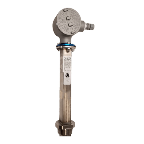
The RediLevel™ 2100 DLS measures and reports fluid levels and temperatures in a variety of tanks and
vessels. The sensor has a thin-profile, sturdy design to fit into tanks with two-inch ports. It is a digital
sensor as it reports the information in a serial bit stream. The sensor uses a float(s) embedded with
magnets to sense the top fluid level(s). A sensor may have one or two floats. A two-float sensor can
measure multiple fluids in a tank. There is a temperature sensor mounted inside the tube fourteen inches
from the bottom. When the sensor is polled for data, a series of microprocessors read and determine the
position of the float(s) along the sensor tube. The main microprocessor then calculates the level and
temperature and returns the data in a serial stream.
Communications
The serial communication protocol is RS485 2-wire or 4-wire, field selectable via jumpers on the fuse
board. The baud rate is set to 9600, N, 8, 1. In 4-wire mode, one pair of wires is used strictly for
transmitting and another pair is for receiving. For 2-wire mode, only one pair of wires is needed for both
transmit and receive. Two wires are needed for the power supply, therefore 4-wire communications
require a 3-pair cable while 2-wire communications require a 2-pair cable.
Wiring Connections
The sensor requires a power supply of 5.6 to 13 volts DC. To connect the sensor communication lines to
the telemetry equipment, connect the sensor data receive to the RTU data transmit and the sensor data
transmit to the RTU data receive. The voltage supply can be connected to a switched output so power is
applied only during sensor polling.
Installation
To install the sensor, follow the simple steps below while referring to the assembly diagram in Figure 2 at
the end of this manual:
1. Install the sensor-grip and a reducer for the tank port size that is to be used. Slide
this assembly onto the bottom of the tube.
2. Install the float stop at the bottom of the sensor tube.
3. Carefully insert the bottom end of the sensor into the tank port and lower the sensor
slowly into the tank. Be careful with the float so it does not hang up on the port
edge.
CAUTION: DO NOT drop the sensor into the tank. The sensor contains glass switches and a
sharp impact will break them, making the sensor inoperable.
4. With the sensor resting on the tank bottom, slide the reducer/sensor-mount
assembly down to the tank port and tighten it onto the port. Tighten the sensor
mount tight enough so the sensor cannot rotate by hand.
5. Unscrew the round side cover from the sensor top housing and feed the signal cable
through the cord grip on the side of the sensor top. Unplug the gray, 6-position
connector from the internal fuse board.
6. Make sure power is off before proceeding.

RediLevel 2100 DLS page 2
EL 29306 © 2022 Electrolab, Inc. All Rights Reserved.
7. Using the white depressor tool, install the six wires (4-wire communication) or four
wires (2- wire communication) as directed in the connection (hook-up) diagram in
Figure 3.
8. Plug in the connector and replace the side cover.
Sensor Calibration Procedure - Setting the Initial Offset
The RediLevel™ 2100 DLS is designed to provide an accurate and dependable level measurement for oil
and water levels in production tanks. The only calibration required is to set the offset value for the
sensor. This can be done in the sensor or at the EFM, RTU, or PLC by determining the difference of the
level between the electronic reading and the actual fluid level in the tank, measured with an approved
gauge line. Once the level offset is entered in either the sensor or SCADA system, the level offset will be
added to the raw value of the sensor to provide an accurate fluid level.
The level offset is determined by reading the sensor with the HHC-1000 Hand-Held Communicator while
simultaneously gauging the level in the tank. For best results, the tank should not be in active production
so that the fluid is not agitated at the time of reading. If it is not possible to isolate the tank, then it is
recommended to take several readings of both the sensor and gauge line to make sure the readings are
consistent.
Note: If there is no fluid in the tank, the level offset cannot be determined.
Note: The level offset is always added to the raw value. If a mistake is made when entering the level
offset, reset the offset value to zero before proceeding to avoid large swings in readings. If there is an
offset programmed in the sensor and the actual level is not correctly displayed, simply changing the
offset value will not include the previous offset value.
Example: If a 1.50” offset is entered and the sensor is still reading ¼” below actual level, the true offset
should be 1.75.” If you add a ¼” offset, the level reading will be 1.50” below actual level. Resetting the
level offset to zero will make it easier to determine the correct offset value.
Procedure:
1. Using the Hand-Held Communicator (HHC-1000), connect to the sensor and take initial
readings of level and temperature. Refer to the HHC -1000 User Manual for instructions.
2. If readings are providing multiple fluid levels, then verify that the two readings are more
than 3” apart. If the difference is less than 3”, the two floats will be touching and a valid
offset cannot be determined.
3. Verify that the first level is more than 3”. If less than 3”, then the bottom float is sitting
on the bottom of the tank and level offset cannot be determined.
4. Using a gauge line, measure the actual level in the tank and note the level. Subtract the
electronic reading from the gauged level to determine the level offset value.
For example, if the actual level is 156.25” and the DLS reading is 155.50,” then the offset
value will be 0.75” (156.25-155.50=0.75).
5. To program the level offset in the sensor using the HHC-1000, go to the “Set Points”
menu and then to the “Level” menu. Press F2 in the “Level” menu to bring up the level
offset screen.

RediLevel 2100 DLS page 3
EL 29306 © 2022 Electrolab, Inc. All Rights Reserved.
6. To set the total fluid level offset, enter a value of 1for the top float and then enter the
offset value. If the value is less than one, enter the decimal value, then press “Enter.”
7. To set the level offset for the bottom float, enter a value of 2for the bottom float, then
enter the offset value, and press “Enter.”
8. To verify that the offset is correct, return to the main screen and then read level and
temperature values to verify the DLS is reading correctly.
9. Once the level offsets are entered, there is no further calibration required unless the DLS
is removed and reinstalled in another tank.
Testing and Troubleshooting
If the sensor fails to respond or does not report an accurate level, several things could be at fault. See the
list of common issues below for help in diagnosing the problem.
Sensor does not respond:
Sensor is new and recently installed:
1. The sensor wiring is incorrect: check the sensor connection (hook-up) diagram.
2. Wrong baud rate: (Factory default is 9600)
3. Wrong protocol: (Factory default is N81)
4. There is insufficient voltage: The sensor needs at least 5.6 VDC.
Sensor has been in service for some time but is not working:
1. There are corroded connections or damaged cables.
2. Blown fuse or shorted suppressor on the barrier board (if equipped). Check the fuses
with a continuity tester.
3. There is possible damage to sensor electronics.
Sensor sends inaccurate level or temperature:
1. An incorrect level or temperature offset is programmed into sensor, RTU, or host.
2. An incorrect number of floats are programmed. Check the sensor protocol list to
reprogram the sensor with the correct information.
Sensor sends temperature but no valid level:
1. If the sensor reports error code 1, the float is not on the sensor in the correct
orientation. The white mark on the float must be on top of the strip on the side of
the sensor.
2. An incorrect number of floats are programmed. Check the sensor protocol command
list to reprogram the sensor with the correct information.
Digital Level Sensor Protocol
Command syntax
1. Uppercase characters denote literals in the command and response streams.
2. Lowercase characters represent data fields in the command and response streams.
Further explanation of data field structure is provided as necessary with each
command.
3. All commands are terminated with carriage return <cr>.

RediLevel 2100 DLS page 4
EL 29306 © 2022 Electrolab, Inc. All Rights Reserved.
4. All responses are terminated with Ccccc (cccc=16 bit CRC field in hexadecimal)
followed by a carriage return linefeed pair <cr><lf>. All alpha hexadecimal characters
are lower case.
5. The prefix to all commands and responses is Uuu where uu is the unit number (00-
31). The unit number is the identity of the level sensor to which a command is
addressed or which generates the response. ‘*’ may be used as a wild card character
for either digit in the unit number field ‘uu’. The responding level sensor will always
convert wildcard characters to the actual unit number.
6. Commands, which modify a level sensor configuration, always return the command
string and ‘OK’ if successful. ‘EEerr’ replaces ‘OK’ if there is a problem storing the
configuration data in the level sensor EEPROM.
Data Request Commands
Report Level and Temperature
Uuu?
where uu is a two-digit unit number from 00 to 31( “*” may be used as a wildcard for either digit)
Note: Do Not use the wildcard “**” if connected to more than one level sensor, as all sensors will respond
simultaneously.
Response: UuuDlll.llFtttEeeeeWwwww
where uu = unit number
lll.ll = level in inches (repeated for sensors with 2 floats)
ttt = temperature in degrees F
eeee = error number
0 = No errors
1= No float detected
2 = One float is out of range on a two-float sensor
3 = Too many groups
4 = (reserved)
5 = Transmit to slave processor for level failed
6 = Transmit to slave processor for temperature failed
7 = Receive from slave processor of level failed
8 = Receive from slave processor of temperature failed
9 = No slave processors responding
Note: If errors 5 through 9 occur and persist after power cycling, the sensor should be returned for repair.
wwww = warning number
0 = No warnings
1 = Possible level degradation
Under normal circumstances the warning field is 0. It will display 1if the sensor is configured for two
floats and only one group of switches is detected (i.e., only one float is present or both floats are
abutted).
Note: The number of decimal places in a data field implies nothing about the accuracy of the
data, i.e., levels are not accurate to 0.01 inches.

RediLevel 2100 DLS page 5
EL 29306 © 2022 Electrolab, Inc. All Rights Reserved.
Report Level and Temperature Continuously (factory diagnostics)
Uuu??
Response: Same as above, except continuously with internal module configuration and reported
individual switch activation and groups of activated switches.
Note: The unit must be powered down before it will respond to other commands.
Report 4-20mA Output Level (version 3.09 and higher)
Uuu?M
Response: UuuMhhhhEeeeeWwwww
Where uu = unit number
hhhh = hex value 0x0000-0xFFFF
eeee = error number
0 = No errors
1= No float detected
2 = One float is out of range on a two-float sensor
3 = Too many groups
4 = (reserved)
5 = Transmit to slave processor for level failed
6 = Transmit to slave processor for temperature failed
7 = Receive from slave processor of level failed
8 = Receive from slave processor of temperature failed
9 = No slave processors responding
Note: If errors 5 through 9 occur and persist after power cycling, the sensor should be returned for repair.
wwww = warning number (0 means “No warnings”)
0 = No warnings
1 = Possible level degradation
Report Temperature Only
Uuu?T
Response: UuuFxxEeeeeWwwww
Where
xx= temperature
Configuration Commands
Assign Unit Number
UuuNnn
Where
uu = unit number (from 00 to 31)
nn = new unit number
Note: Unit number 00 is not valid in Modbus RTU mode
Response: UuuNOK
Where
uu = newly assigned unit number

RediLevel 2100 DLS page 6
EL 29306 © 2022 Electrolab, Inc. All Rights Reserved.
Assign Unit Number to Sensor With the Corresponding Serial Number (version
3.15 and higher)
UsssssssNnn
sssssss = seven-digit serial number
nn = two-digit unit number
Response:
UuuNOK uu = new unit number
UuuEEerr Write to EEPROM failed
Set Baud Rate
UuuBbbbb[b][pds]
Where
bbbb[b] = 1200, 9600, 14400, 19200, 38400, or 57600 (9600 is default) (v3.15 and higher)
pds = parity, data length, stop bit (pds options)
N81 (default)
E71
O71
For example, to program Unit 00 to 9600 E 7 1 would be U00B9600E71
Note: It is not necessary to power down the Model 2100 before this command takes effect. The Model
1000 must have power cycled for this command to take effect.
Response: UnnBOK
Set Number of Floats
UuuFn
Where
uu = unit number
n = float number (1 or 2 – Standard; 11 or 12 – 1/8” Resolution; 11 – Single Float; 12 – Dual Float)
Response: UuuFOK
Set Level Offset
UuuLOslll Sets the offset for the level sensor
Where
uu = unit number
sIIlI = sign and offset with two implied decimal places
Note: If two floats, assigns the same offset to both
Response: UuuOLOK
Set Level Offsets for Individual Floats
UuuL[1|T]Oslll.ll Sets the top float offset.
Example of setting top level offset for Unit 00 to 2.25 inches - U00L1O2.25
UuuL[2|B]Oslll.ll Sets the bottom float offset. (Dual Float Sensor only)
Example of setting bottom level offset for water interface to 1.75 inches - U00L2O1.75
Where
uu = unit number

RediLevel 2100 DLS page 7
EL 29306 © 2022 Electrolab, Inc. All Rights Reserved.
slll.ll = sign and offset with two implied decimal places.
The Plus (+) sign is assumed.
The Minus (-) must precede the offset value if required.
If no decimal places are required, then you do not need to add to value
Note: "O" in the command is the letter Oand not the number zero
Response: UuuLOOK
Set Temperature Offset
UuuOFsoo
Where
uu = unit number
soo = -99 to 99 (optional sign)
Response: UuuOFOK
Set Multiple Temperature Sensor Offsets
UuuTnOso.o
Where
uu = unit number
n = temperature sensor identifier (1-8, 1 is at top)
so.o = -9.9 to 9.9 degrees (optional sign)
Response: UuuTnOOK
Set Receive to Transmit Delay
UuuRmmm
Where
uu = unit number
mmm = milliseconds (50 to 250). The default is 127ms
Response: UuuROK
Set 4-20mA Poll Period
UuuMPpppp
Where
uu = unit number
pppp = seconds (Default is 30 seconds)
Response: UuuMPOK
Note:Poll Periods less than 20 seconds may shorten the life expectancy of the 4/20mA converter board.
The relay (which power cycles the sensor to reduce power consumption) is rated for 10,000,000 cycles.
Set 4-20mA Minimum (4mA) Range
UuuMINmm.mm
Where
uu = unit number
mm.mm = level for 4mA output (Default is 00.00)
Response: UuuMINOK

RediLevel 2100 DLS page 8
EL 29306 © 2022 Electrolab, Inc. All Rights Reserved.
Set 4-20mA Maximum (20mA) Range
UuuMAXmmm.mm
Where
uu = unit number
mmm.mm = level for 20mA output in inches (Default is 240.00”)
Example: For 20-foot long sensors = 240.00
Response: UuuMAXOK
Set the Level Error setting (version 3.09 and higher)
UuuSETERRx
Where
uu = unit number
x = 0 will set the level error report to be 999.99. This is the default setting.
x = 1 will set the level error report to be 000.00.
Response: UuuSETERROK
Set the Modbus 16 bit Unsigned Integer, 32 bit or 2 x 16 bit floating point mode
UuuIFxxxx
Where
uu = unit number
xxxx = 1007 will set the 16 bit Unsigned integer mode. This is the default setting.
xxxx = 1008 will set the 32 bit floating point mode.
xxxx = 1009 will set the 2x16 bit floating point mode (v3.14 and higher).
Response: UuuIFOK
Force sensor to enter Boot Load mode (version 3.15 and higher, (future use)
UUUFB
uu = two-digit unit number
Response: none
Enter High Level Electronic Shut Down (ESD mode) (version 3.15 and higher)
UuuESDONn
uu = unit number
n = one-digit number from 1 to 3 which represent the number of level request commands that will respond
with the maximum level without cycling power. After this number, the sensor reverts to normal operation
(Note: If power is cycled the count reverts back to programmed number of polls).
Response: UuuESDONOK ESD mode was successfully activated
Exit High Level Electronic Shut Down (ESD mode) (version 3.15 and higher)
UuuESDOFF
Response: UuuESDOFFOK ESD mode exit successfully
Note: UuuESDON0 also turns off ESD mode

RediLevel 2100 DLS page 9
EL 29306 © 2022 Electrolab, Inc. All Rights Reserved.
Configuration Request Commands
Report Number of Floats
UuuF?
Response: UuuFn
Where
uu = unit number
n = number of floats (1 or 2 – Standard; 11 or 12 – 1/8” Resolution; 11 – Single Float; 12 – Dual Float)
Report Level Offsets
UuuLO?
Response: UuuL1Osnn.nnL2Osnn.nn
Where
uu = unit number
snn.nn = sign and offset with two implied decimal places
Report Temperature Offset
UuuOF?
Response: UuuOFsff
Where
uu = unit number
s = sign
ff = temperature offset (degrees F)
Report Multiple Temperature Offsets
UuuTO?
Response: UuuTnOso.o…..TnOsn.n repeated for additional temperature sensors
Where
uu = unit number
n = temperature sensor (1-8, 1 is top sensor)
s = sign
o.o = temperature offset
Report Switch Distance
UuuD?
Response: UuuDd
Where
uu = unit number
d = distance between switches as integral tenths of an inch (e.g., 5 = 0.5 inches, 10 = 1 inches)
Report Total Switches
UuuS?
Response: UuuSssss
Where
uu = unit number
ssss = total number of switches in the sensor
Report Receive to Transmit delay
UuuR?
Response: UuuRmmm

RediLevel 2100 DLS page 10
EL 29306 © 2022 Electrolab, Inc. All Rights Reserved.
Where
uu = unit number
mmm = delay in milliseconds
Report 4-20mA Configuration
UuuMC?
Response: UuuPppppL1_4MAll.ll_20MAhhh.hh
Where
uu = unit number
Ppppp = Polling period in seconds
L1 = Data source is top float
_4MAll.ll = Level to output 4 mA
_20MAhhh.hh = Level to output 20 mA
Report Serial Number
UuuSN?
Response: UuuSNxxxxxxx
Where
uu = unit number
xxxxxxxx = serial number.
Report Unit Number corresponding to Serial Number (version 3.15 and higher)
UsssssssN?
sssssss seven digit serial number
Response: UsssssssNuu
uu = unit number
Report sensor Health Status (version 3.15 and higher)
UuuH?
uu =two digit unit number
Response:
grp0=ttt-bbb--grp1=ttt-bbb
grp3=ttt-bbb--grp4=ttt-bbb
UuuDlll.ll[Dlll.ll]Fttt[Fttt……]EeeeeWwwww
BATTERY-VOLTAGE:vv.vV
If sensor works in normal operation parameters the message will be
UuuSENSOR-OK
Error, one or more of the following Error messages
NO-SWITCH-CLOSED
ONLY-ONE-GROUP-FOUND-ON-A-TWO-FLOAT-SYSTEM
TOO-MANY-GROUPS-TO-RESOLVE-THE-LEVEL
NO-FLOAT-CONFIGURED
TRANSMIT-TO-PIC-PROCESSOR-FOR-LEVEL-FAILED
RECEIVE-FROM-PIC-PROCESSOR-FOR-LEVEL-FAILED
TRANSMIT-TO-PIC-PROCESSOR-FOR-TEMP-FAILED
RECEIVE-FROM-PIC-PROCESSOR-FOR-TEMP-FAILED
Warning, one or both of the following Warning messages:

RediLevel 2100 DLS page 11
EL 29306 © 2022 Electrolab, Inc. All Rights Reserved.
WARNING!-POSSIBLE-LEVEL-DEGRADATION
WARNING!-POSSIBLE-LEVEL-DEGRADATION-DUE-TO-OFFSET
Report the Level Error Setting (version 3.09 and higher)
UuuSETERR?
Response: UuuSETERR=x
Where
uu = unit number
x = 0 is set for level error report to be 999.99 (default)
x = 1 is set for level error report to be 000.00
Report the Modbus 16 bit Unsigned Integer, 32 bit or 2 x 16 bit floating point mode
UuuIF?
Response: UuuIF=x
Where
uu = unit number
x = 0 is set for 16 bit Unsigned integer mode. This is the default setting.
x = 1 is set for 32 bit floating point mode.
x = 2 is set for 2x16 bit floating point mode (v3.14 and higher)
Report Battery Voltage
UuuBV?
Response: UuuBVvv.vV
Where
uu = unit number
vv.v = battery voltage in volts

RediLevel 2100 DLS page 12
EL 29306 © 2022 Electrolab, Inc. All Rights Reserved.
Modbus Registry Map
Read/Write functions are given in Table 1. The read only functions in the holding registry are referenced
in Table 2 & Table 3. The sensor warnings codes are provided in Table 4. Error codes are given in Table 5.
Table 1. Read/Write Registers
Configuration
Registers
Register
Read/Write
Address No.
Reg.
Notes Integer Type
ESD ON: 0 = ESD off
1 to 3 ESD
ON, 1 to 3 times
40106
105
1
R/W Factory
setting: 0
16 bit
Unsigned
(v3.15 and
higher)
Assign Sensor unit
number
40107
106
1
Default value is
1
16 bit
Unsigned
Select 16 bit
unsigned integer (0)
or 32 bit floating
point (1) for registers
that hold top float,
bottom float, and
temperature or 2x 16
bit floating point (2)
40108
107
1
Factory setting:
16 bit
unassigned
integer (see
Note for
advanced
users)
16 bit
Unsigned
Set baud rate (1200,
9600, 14400, 19200,
38400) ( 57600 V3.15
and higher)
40109
108
1
Factory setting:
9600
16 bit
Unsigned
Set parity:
78 (N) = No parity
79 (O) = Odd parity
69 (E) = Even parity
40110
109
1
Factory setting:
78 (N)
16 bit
Unsigned
Set data bit: 8
40111
110
1
Factory setting:
8
16 bit
Unsigned
Set stop bit: 1
40112
111
1
Factory setting:
1
16 bit
Unsigned
Rx to Tx delay [ms]:
50 to 250
40113
112
1
Factory setting:
127
16 bit
Unsigned
Set number of floats:
1, 2, 11 or 12
40114
113
1
Factory setting:
1
16 bit
Unsigned
Level error report: 0
or 1
40115
114
1
Factory setting:
0
16 bit
Unsigned
K factor x 100: 10 to
1000 bbls/in
40116
115
1
Factory setting:
167
16 bit
Unsigned
Top level offset x
100: -9999 to 9999
40117
116
1
Factory setting:
0
16 bit Signed
Bottom level offset x
100: -9999 to 9999
40118
117
1
Factory setting:
0
16 bit Signed

RediLevel 2100 DLS page 13
EL 29306 © 2022 Electrolab, Inc. All Rights Reserved.
Temperature offset1
x 10: -99 to 99
40119
118
1
Factory setting:
0
16 bit Signed
Temperature offset2
x 10: -99 to 99
40120
119
1
Factory setting:
0
16 bit Signed
Temperature offset2
x 10: -99 to 99
40121
120
1
Factory setting:
0
16 bit Signed
Temperature offset4
x 10: -99 to 99
40122
121
1
Factory setting:
0
16 bit Signed
Temperature offset5
x 10: -99 to 99
40123
122
1
Factory setting:
0
16 bit Signed
Temperature offset6
x 10: -99 to 99
40124
123
1
Factory setting:
0
16 bit Signed
Temperature offset7
x 10: -99 to 99
40125
124
1
Factory setting:
0
16 bit Signed
Temperature offset8
x 10: -99 to 99
40126
125
1
Factory setting:
0
16 bit Signed
Sensor Description Registers
Serial number high
40127
126
1
Read only
16 bit
Unsigned
Serial number
medium high
40128
127
1
Read only
16 bit
Unsigned
Serial number
medium low
40129
128
1
Read only
16 bit
Unsigned
Serial number low
40130
129
1
Read only
16 bit
Unsigned
Version number
40131
130
1
Read only
16 bit
Unsigned
Number of modules:
1 to 8
40132
131
1
Read only
16 bit
Unsigned
Number of switches
40133
132
1
Read only
16 bit
Unsigned
Switch distance x 10:
5 or 10
40134
133
1
Read only
16 bit
Unsigned
Number of
temperature sensors:
1 to 8
40135
134
1
Read only
16 bit
Unsigned
Sensor status: 0 or 1,
0= Good
1= Sensor errors or
low battery
40136
135
1
Read only
16 bit
Unsigned
(v3.15 and
higher)
Group 0 top
40137
136
1
Read only
16 bit
Unsigned
(v3.15 and
higher)
Group 0 bottom
40138
137
1
Read only
16 bit
Unsigned
(v3.15 and
higher)

RediLevel 2100 DLS page 14
EL 29306 © 2022 Electrolab, Inc. All Rights Reserved.
Group 1 top
40139
138
1
Read only
16 bit
Unsigned
(v3.15 and
higher)
Group 1 bottom
40140
139
1
Read only
16 bit
Unsigned
(v3.15 and
higher)
Group 2 top
40141
140
1
Read only
16 bit
Unsigned
(v3.15 and
higher)
Group 2 bottom
40142
141
1
Read only
16 bit
Unsigned
(v3.15 and
higher)
Group 3 top
40143
142
1
Read only
16 bit
Unsigned
(v3.15 and
higher)
Group 3 bottom
40144
143
1
Read only
16 bit
Unsigned
(v3.15 and
higher)

RediLevel 2100 DLS page 15
EL 29306 © 2022 Electrolab, Inc. All Rights Reserved.
Table 2. Holding Registers
Sensor Data
Register
Address
No. Reg.
Values
Type
Float 1 (Top
Float)
43991
3990
1
Read Only
Total Fluid Level in Tank
16 bit Unsigned integer or 32 bit
floating point
Float 2
(Bottom
Float)
43992
3991
1
Read Only
Water Interface Level in Tank
16 bit Unsigned integer or 32 bit
floating point
Oil Level in
Tank (top to
bottom)
43993
3992
1
Read Only
Oil Level in Tank (top-bottom)
16 bit Unsigned integer or 32 bit
floating point
Total Volume
(top level x
K_factor)
43994
3993
1
Read Only
Total Volume (top level x K
factor)
16 bit Unsigned integer or 32 bit
floating point
Oil Volume
(top level –
bottom level)
x K_factor
43995
3994
1
Read Only
Oil Volume
16 bit Unsigned integer or 32 bit
floating point
Water
Volume
(bottom level
x K_factor)
43996
3995
1
Read Only
Water Volume
16 bit Unsigned integer or 32 bit
floating point
Temperature1
43997
3996
1
Read Only
Temperature1
16 bit Unsigned integer or 32 bit
floating point
Temperature2
43998
3997
1
Read Only
Temperature2
16 bit Unsigned integer or 32 bit
floating point
Temperature3
43999
3998
1
Read Only
Temperature3
16 bit Unsigned integer or 32 bit
floating point
Temperature4
44000
3999
1
Read Only
Temperature4
16 bit Unsigned integer or 32 bit
floating point
Temperature5
44001
4000
1
Read Only
Temperature5
16 bit Unsigned integer or 32 bit
floating point
Temperature6
44002
4001
1
Read Only
Temperature6
16 bit Unsigned integer or 32 bit
floating point
Temperature7
44003
4002
1
Read Only
Temperature7
16 bit Unsigned integer or 32 bit
floating point
Temperature8
44004
4003
1
Read Only
Temperature8
16 bit Unsigned integer or 32 bit
floating point
Battery
Voltage
44005
4004
1
Read Only
Battery Voltage (*100 for 16
bit)

RediLevel 2100 DLS page 16
EL 29306 © 2022 Electrolab, Inc. All Rights Reserved.
16 bit Unsigned integer or 32 bit
floating point
Error
Register:
44006
4005
1
Read Only
16 bit Unsigned integer (See
Notes)
Warnings
Register:
44007
4006
1
Read Only
16 bit Unsigned integer (See
Notes)
Table 3. Holding Registers (2 x 16 bit)
Sensor Data
Register
Address
No.
Reg.
Values
Type
Float 1 (Top
Float)
45001
5000
2
Read
Only
Total Fluid Level in Tank
Floating point upper two bytes
(v3.14 and higher)
45002
5001
Read
Only
Total Fluid Level in Tank
Floating point lower two bytes
(v3.14 and higher)
Float 2 (Bottom
Float)
45003
5002
2
Read
Only
Water Interface Level in Tank
Floating point upper two bytes
(v3.14 and higher)
45004
5003
Read
Only
Water Interface Level in Tank
Floating point lower two bytes
(v3.14 and higher)
Oil Level in
Tank (top to
bottom)
45005
5004
2
Read
Only
Oil Level in Tank(top-bottom)
Floating point upper two bytes
(v3.14 and higher)
45006
5005
Read
Only
Oil Level in Tank(top-bottom)
Floating point lower two bytes
(v3.14 and higher)
Total Volume
(top level x K
factor)
45007
5006
2
Read
Only
Total Volume(top level x K factor)
Floating point upper two bytes
(v3.14 and higher)
45008
5007
Read
Only
Total Volume(top level x K factor)
Floating point lower two bytes
(v3.14 and higher)
Oil Volume (top
level – bottom
level) x K factor
45009
5008
2
Read
Only
Oil Volume (v3.14 and higher)
Floating point upper two bytes
45010
5009
Read
Only
Oil Volume (v3.14 and higher)
Floating point lower two bytes
Water Volume
(bottom level x
K factor)
45011
5010
2
Read
Only
Water Volume(bottom level x K factor)
Floating point upper two bytes
(v3.14 and higher)
45012
5011
Read
Only
Water Volume(bottom level x K factor)
Floating point lower two bytes
(v3.14 and higher)
Temperature1
45013
5012
2
Read
Only
Temperature1 (v3.14 and higher)
Floating point upper two bytes
Table of contents
Other Electrolab Accessories manuals
