autosen AL002 User manual

Bedienungsanleitung
Optischer Abstandssensor
Operating instructions
Optical distance sensor
Notice d‘utilisation
Détecteur de distance optique
autosen AL002
200479 / 01 08 / 2015
Made in Germany
DE
UK
FR

2
Inhalt
1 Vorbemerkung �����������������������������������������������������������������������������������������������������3
1�1 Verwendete Symbole�������������������������������������������������������������������������������������3
1�2 Verwendete Warnhinweise ����������������������������������������������������������������������������3
2 Sicherheitshinweise���������������������������������������������������������������������������������������������3
3 Bestimmungsgemäße Verwendung���������������������������������������������������������������������5
3�1 Einsatzbereiche ���������������������������������������������������������������������������������������������5
4 Montage���������������������������������������������������������������������������������������������������������������5
4�1 Montagebedingungen������������������������������������������������������������������������������������5
5 Bedien- und Anzeigeelemente�����������������������������������������������������������������������������5
6 Elektrischer Anschluss�����������������������������������������������������������������������������������������6
7 Einstellungen �������������������������������������������������������������������������������������������������������7
7�1 Gerät soll schalten, wenn das Objekt erkannt wird ���������������������������������������7
8 IO-Link �����������������������������������������������������������������������������������������������������������������7
8�1 Allgemeine Informationen ������������������������������������������������������������������������������7
8�2 Gerätespezifische Informationen�������������������������������������������������������������������7
8�3 Parametrierwerkzeuge ����������������������������������������������������������������������������������8
9 Betrieb �����������������������������������������������������������������������������������������������������������������8
9�1 Elektronisches Schloss����������������������������������������������������������������������������������8
9�2 Fehleranzeigen����������������������������������������������������������������������������������������������8
10 Wartung, Instandsetzung und Entsorgung ��������������������������������������������������������9
3
DE
1 Vorbemerkung
1.1 Verwendete Symbole
►Handlungsanweisung
> Reaktion, Ergebnis
[…] Bezeichnung von Tasten, Schaltflächen oder Anzeigen
→Querverweis
Wichtiger Hinweis
Fehlfunktionen oder Störungen sind bei Nichtbeachtung möglich�
1.2 Verwendete Warnhinweise
WARNUNG
Warnung vor schweren Personenschäden�
Tod oder schwere, irreversible Verletzungen sind möglich�
2 Sicherheitshinweise
• Lesen Sie vor der Inbetriebnahme des Gerätes dieses Dokument� Vergewis-
sern Sie sich, dass sich das Produkt uneingeschränkt für die betreffenden
Applikationen eignet�
• Unsachgemäßer oder nicht bestimmungsgemäßer Gebrauch können zu
Funktionsstörungen des Gerätes oder zu unerwünschten Auswirkungen in Ihrer
Applikation führen� Deshalb dürfen Montage, elektrischer Anschluss, Inbetrieb-
nahme, Bedienung und Wartung des Gerätes nur durchgeführt werden durch
ausgebildetes, vom Anlagenbetreiber autorisiertes Fachpersonal�
• Bei Fehlfunktion des Gerätes setzen Sie sich mit dem Hersteller in Verbindung�
Eingriffe und/oder Veränderungen am Gerät führen zum Ausschluss jeglicher
Haftung und Gewährleistung�
• Das Gerät entspricht der Norm EN 61000-6-4� In Haushaltsumgebungen kann
das Gerät Rundfunkstörungen verursachen� Sollten Störungen auftreten, muss
der Anwender durch geeignete Maßnahmen für Abhilfe sorgen�
4
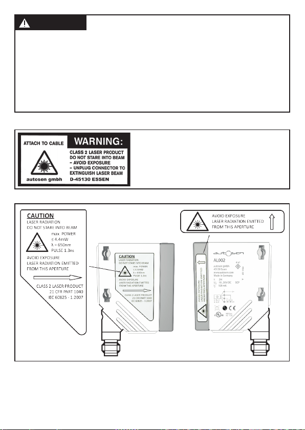
WARNUNG
Sichtbares Laserlicht; Laserschutzklasse 2�
Die Verwendung von anderen Bedieneinrichtungen oder -einstellungen kann zu gefähr-
licher Strahlungsexposition führen� Schädigung der Netzhaut ist möglich�
►Nicht in den Laserstrahl blicken!
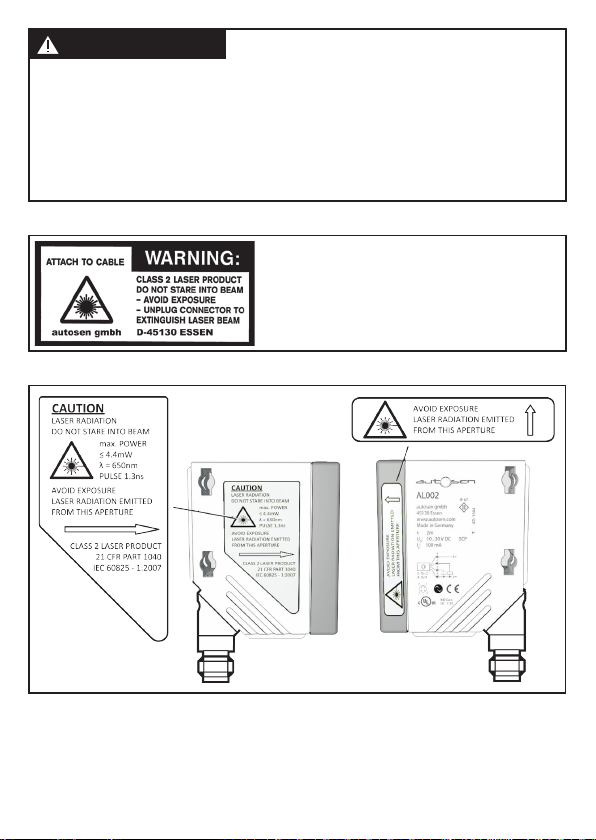
►Die beigelegten Aufkleber (Warnhinweis Laser) in unmittelbarer Nähe des Geräts
anbringen�
►Die Vorsichts- und Warnhinweise auf dem Produktlabel beachten�
►Das beigefügte Label für das Versorgungskabel verwenden�
Label für Versorgungskabel
Position des Produktlabels

5
DE
3 Bestimmungsgemäße Verwendung
Das Gerät wird als optischer Abstandssensor eingesetzt�
3.1 Einsatzbereiche
• Der optische Abstandssensor misst Entfernungen von 0,03 bis 2 m
• Er besitzt eine Hintergrundausblendung bis 20 m�
• Die Schaltausgänge sind antivalent�
Der Abstand zwischen Sensor und Hintergrund muss kundenseitig auf
max� 20 m begrenzt werden� Ansonsten können Messwerte mehrdeutig
sein.→4.1Montagebedingungen
4 Montage
4.1 Montagebedingungen
►Gerät so montieren, dass sich das zu erfassende Objekt im Messbereich von
0,03���2 m befindet�
Objekte, die hinter dem eingestellten Schaltpunkt liegen, werden bis 20 m ausge-
blendet�
Reflektierende Oberflächen im direkten Strahlengang des Sensors – auch
im Bereich > 20 m – sind kundenseitig zu vermeiden� Ansonsten können
die Messwerte mehrdeutig sein�
5 Bedien- und Anzeigeelemente
1: LED grün: Betrieb
2: LED gelb: Schaltzustand
3: 3-stellige alphanumerische Anzeige
4: Tastweite +
5: Tastweite -

6
6 Elektrischer Anschluss
Das Gerät darf nur von einer Elektrofachkraft installiert werden�
►Befolgen Sie die nationalen und internationalen Vorschriften zur Errich-
tung elektrotechnischer Anlagen�
►Spannungsversorgung nach EN 50178 sicherstellen�
►Anlage spannungsfrei schalten�
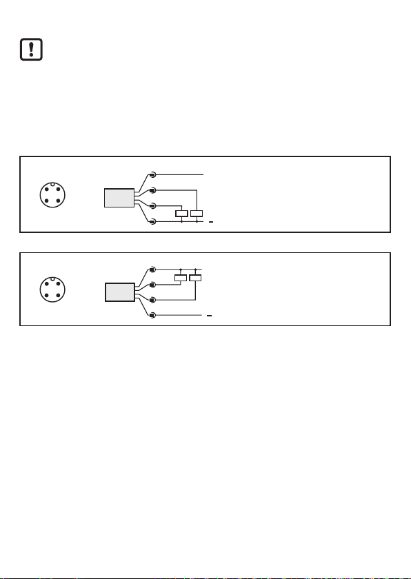
►Gerät folgendermaßen anschließen:
DC PNP
43
2
1
4: OUT1 = Schließer / IO-Link
2: OUT2 = Öffner
DC NPN
43
2
1
4: OUT1 = Schließer / IO-Link
2: OUT2 = Öffner
Adernfarben bei autosen-Kabeldosen:
1 = BN (braun), 2 = WH (weiß), 3 = BU (blau), 4 = BK (schwarz)

7
DE
7 Einstellungen
7.1 Gerät soll schalten, wenn das Objekt erkannt wird
►Das Objekt platzieren�
►[+] drücken, um den Schaltabstand zu vergrößern�
> Der eingestellte Abstandswert wird blinkend im Display angezeigt�
> Die gelbe LED leuchtet, wenn das Objekt erkannt wird�
►[-] drücken, um den Schaltabstand zu verkleinern�
> Der eingestellte Abstandswert wird blinkend im Display angezeigt�
> Während des Betriebs wird der aktuell ermittelte Abstandswert im Display angezeigt�
8 IO-Link
8.1 Allgemeine Informationen
Dieses Gerät verfügt über eine IO-Link-Kommunikationsschnittstelle, welche für
den Betrieb eine IO-Link-fähige Baugruppe (IO-Link-Master) voraussetzt�
Die IO-Link-Schnittstelle ermöglicht den direkten Zugriff auf Sensorwerte und
Parameter und bietet die Möglichkeit, das Gerät im laufenden Betrieb zu parame-
trieren�
Des Weiteren ist die Kommunikation über eine Punkt-zu-Punkt-Verbindung mit
einem USB-Adapterkabel möglich�
Weitere Informationen zu IO-Link finden Sie unter www�autosen�com
Gerätespezifische Informationen
Die zur Konfiguration des IO-Link-Gerätes notwendigen IODDs sowie detaillierte
Informationen über Sensorwerte, Diagnoseinformationen und Parameter finden
Sie unter www�autosen�com
8
Parametrierwerkzeuge
Alle notwendigen Informationen zur benötigten IO-Link-Hardware und Software
finden Sie unter www�autosen�com�
Betrieb
►Prüfen, ob das Gerät sicher funktioniert�
> LED leuchtet wenn der Schaltausgang geschaltet ist�
> Der ermittelte Abstandswert wird im Display angezeigt�
8.2 Elektronisches Schloss
Um unbeabsichtigte Fehleingaben zu verhindern, lässt sich das Gerät elektronisch
verriegeln� Im Auslieferungszustand ist das Gerät nicht verriegelt�
Verriegeln
►Sicherstellen, dass das Gerät im normalen Arbeitsbetrieb ist�
►[+] + [-] gedrückt halten, bis [Loc] angezeigt wird�
> Das Gerät ist verriegelt�
Entriegeln
►[+] + [-] gedrückt halten, bis [uLo] angezeigt wird�
> Das Gerät ist entriegelt�
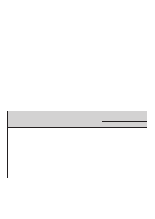
8.3 Fehleranzeigen
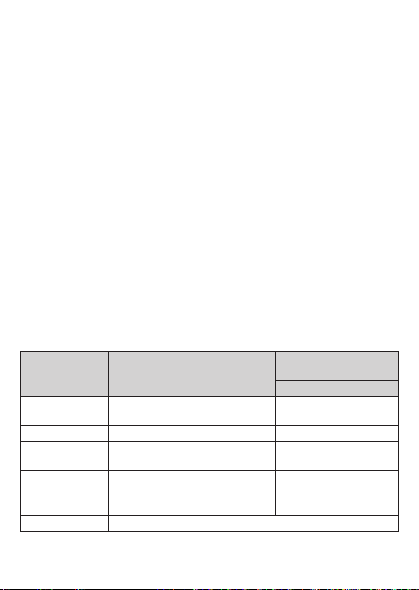
Anzeige Mögliche Ursache Schaltausgang
[Hno] [Hnc]
[++] zu viel Licht,
z� B� spiegelnde Oberflächen ON OFF
[--] zu wenig Licht, kein Objekt OFF ON
[nEA] Messobjekt außerhalb des Messbe-
reichs < 30 mm ON OFF
[FAr] Messobjekt außerhalb des Messbe-
reichs > 2500 mm OFF ON
[ERP] Plausibilität (z�B� Objekt zu schnell) unverändert unverändert
[SC] Kurzschluss am Schaltausgang

9
DE
9 Wartung, Instandsetzung und Entsorgung
►Die Frontscheibe des Geräts von Verschmutzungen freihalten�
►Zur Reinigung keine Lösungsmittel oder Reiniger verwenden, die den Kunst-
stoff beschädigen könnten�
►Das Modulgehäuse nicht öffnen� Es befinden sich keine Komponenten im
Inneren, die vom Benutzer selbst gewartet werden könnten�
Technische Daten und weitere Informationen unter www�autosen�com

10
Contents
1 Preliminary note������������������������������������������������������������������������������������������������� 11
1�1 Symbols used ���������������������������������������������������������������������������������������������� 11
1�2 Warning signs used ������������������������������������������������������������������������������������� 11
2 Safety instructions ��������������������������������������������������������������������������������������������� 11
3 Functions and features ��������������������������������������������������������������������������������������13
3�1 Applications �������������������������������������������������������������������������������������������������13
4 Installation����������������������������������������������������������������������������������������������������������13
4�1 Installation conditions ����������������������������������������������������������������������������������13
5 Operating and display elements ������������������������������������������������������������������������13
6 Electrical connection������������������������������������������������������������������������������������������14
7 Settings��������������������������������������������������������������������������������������������������������������15
7�1 The sensor is to switch when the object is detected������������������������������������15
8 IO-Link ���������������������������������������������������������������������������������������������������������������15
8�1 General information �������������������������������������������������������������������������������������15
8�2 Device-specific information��������������������������������������������������������������������������15
8�3 Parameter setting tools��������������������������������������������������������������������������������15
9 Operation�����������������������������������������������������������������������������������������������������������16
9�1 Electronic lock����������������������������������������������������������������������������������������������16
9�2 Fault indication ��������������������������������������������������������������������������������������������16
10 Maintenance, repair and disposal��������������������������������������������������������������������17
11
UK
1 Preliminary note
1.1 Symbols used
►Instruction
> Reaction, result
[…] Designation of pushbuttons, buttons or indications
→Cross-reference
Important note
Non-compliance can result in malfunctions or interference�
1.2 Warning signs used
WARNING
Warning of serious personal injury�
Death or serious irreversible injuries may result�
2 Safety instructions
• Please read this document prior to set-up of the unit� Ensure that the product is
suitable for your application without any restrictions�
• Improper or non-intended use may lead to malfunctions of the unit or to unwan-
ted effects in your application� That is why installation, electrical connection,
set-up, operation and maintenance of the unit must only be carried out by
qualified personnel authorised by the machine operator�
• In case of malfunction of the unit please contact the manufacturer� If the unit is
tampered with and/or modified, any liability and warranty is excluded�
• The unit conforms to the standard EN 61000-6-4� The unit may cause radio
interference in domestic areas� If interference occurs, the user must take
appropriate remedial actions�

12
WARNING
Visible laser light; laser protection class 2�
Use of controls or adjustments other than those specified herein may result in hazardous
radiation exposure� Damage to the retina is possible�
►Do not stare into the laser beam!
►Apply the enclosed labels (laser warning) in the immediate vicinity of the unit�
►Adhere to the caution and warning notes on the product label�
►Use the enclosed label for the power supply cable�
Label for supply cable
Product label

13
UK
3 Functions and features
The unit is used as an optical distance sensor�
3.1 Applications
• The optical distance sensor measures distances between 0�03 and 2 m�
• It has a background suppression of up to 20 m�
• The switching outputs are complimentary�
The distance between the sensor and the background must be limited to
max� 20 m by the customer� Otherwise the measured value may be ambi-
guous.→4.1Installationconditions
4 Installation
4.1 Installation conditions
►Install the unit so that the object to be detected is within a measuring range of
0�03���2 m�
Any object between the set switch point and a distance of 20 m from the sensor is
suppressed�
Reflecting objects in the direct beam path of the sensor - also in the range
> 20 m – are to be avoided by the customer� Otherwise the measured
values may be ambiguous�
5 Operating and display elements
1: LED green: operation
2: LED yellow: switching status
3: 3-digit alphanumeric display
4: Range +
5: Range -
14
6 Electrical connection
The unit must be connected by a qualified electrician�
►The national and international regulations for the installation of electri-
cal equipment must be adhered to�
►Voltage supply according to EN 50178�
►Disconnect power�
►Connect the unit as follows:
DC PNP
43
2
1
4: OUT1 = normally open / IO-Link
2: OUT2 = normally closed
DC NPN
43
2
1
4: OUT1 = normally open / IO-Link
2: OUT2 = normally closed
Core colours of autosen sockets:
1 = BN (brown), 2 = WH (white), 3 = BU (blue), 4 = BK (black)

15
UK
7 Settings
7.1 The sensor is to switch when the object is detected
►Position the object�
►Press [+] to increase the range�
> The set distance value is shown flashing in the display�
> The yellow LED lights when the object is detected�
►Press [-] to decrease the range�
> The set distance value is shown flashing in the display�
> During operation, the currently detected distance value is shown in the display�
8 IO-Link
8.1 General information
This unit has an IO-Link communication interface which requires an IO-Link-
capable module (IO-Link master) for operation�
The IO-Link interface enables direct access to the sensor values and parameters
and provides the possibility to set the parameters of the unit during operation�
In addition communication is possible via a point-to-point connection with a USB
adapter cable�
You will find more detailed information about IO-Link at www�autosen�com�
Device-specific information
You will find the IODDs necessary for the configuration of the IO-Link unit and
detailed information about sensor values, diagnostic information and parameters
at www�autosen�com�
Parameter setting tools
You will find all necessary information about the required IO-Link hardware and
software at www�autosen�com�
16
Operation
►Check whether the unit operates correctly�
> The LED lights when the switching output is switched�
> The detected distance value is shown in the display�
8.2 Electronic lock
The unit can be locked electronically to prevent unintentional settings� On delivery
the unit is not locked�
Locking
►Make sure that the unit is in the normal operating mode�
►Keep [+] + [-] pressed, until [Loc] is displayed�
> The unit is locked�
Unlocking
►Keep [+] + [-] pressed, until [uLo] is displayed�
> The unit is unlocked�
8.3 Fault indication
Display Possible cause Switching output
[Hno] [Hnc]
[++] Too much light,
e�g� reflective surfaces ON OFF
[--] Not enough light, no object OFF ON
[nEA] Object to be measured outside the
measuring range < 30 mm ON OFF
[FAr] Object to be measured outside the
measuring range > 2500 mm OFF ON
[ERP] Plausibility (e�g� object too fast) unchanged unchanged
[SC] Short circuit at the switching output

17
UK
9 Maintenance, repair and disposal
►Keep the front pane of the sensor free from soiling�
►For cleaning do not use any solvents or cleaning agents which could damage
the plastic material�
►Do not try to open the module enclosure� There are no user-serviceable com-
ponents inside�
Technical data and further information at www�autosen�com

18
Contenu
1 Remarque préliminaire ����������������������������������������������������������������������������������������3
1�1 Symboles utilisés�������������������������������������������������������������������������������������������3
1�2 Avertissements utilisés ����������������������������������������������������������������������������������3
2 Consignes de sécurité �����������������������������������������������������������������������������������������3
3 Fonctionnement et caractéristiques���������������������������������������������������������������������5
3�1 Applications ���������������������������������������������������������������������������������������������������5
4 Montage���������������������������������������������������������������������������������������������������������������5
4�1 Conditions de montage����������������������������������������������������������������������������������5
5 Eléments de service et d‘indication ���������������������������������������������������������������������5
6 Raccordement électrique�������������������������������������������������������������������������������������6
7 Réglage ���������������������������������������������������������������������������������������������������������������7
7�1 L‘appareil doit commuter lorsque l‘objet est détecté �������������������������������������7
8 IO-Link �����������������������������������������������������������������������������������������������������������������7
8�1 Informations générales ����������������������������������������������������������������������������������7
8�2 Informations spécifiques à l‘appareil �������������������������������������������������������������7
8�3 Outils de paramétrage �����������������������������������������������������������������������������������8
9 Fonctionnement���������������������������������������������������������������������������������������������������8
9�1 Verrou électronique ���������������������������������������������������������������������������������������8
9�2 Messages d’erreur�����������������������������������������������������������������������������������������8
10 Maintenance, réparation, élimination�����������������������������������������������������������������9

19
FR
1 Remarque préliminaire
1.1 Symboles utilisés
►Action à faire
> Retour d'information, résultat
[…] Désignation d'une touche, d'un bouton ou d'un affichage
→Référence
Remarque importante
Le non-respect peut aboutir à des dysfonctionnements ou perturbations�
1.2 Avertissements utilisés
AVERTISSEMENT
Avertissement de dommages corporels graves�
Danger de mort ou de graves blessures irréversibles�
2 Consignes de sécurité
• Avant la mise en service de l‘appareil, lire cette notice� S‘assurer que le produit
est approprié pour l‘application concernée sans aucune restriction d‘utilisation�
• L‘emploi non approprié ou incorrect peut mener à des défauts de fonction-
nement de l‘appareil ou à des effets non désirés dans votre application�
C‘est pourquoi le montage, le raccordement électrique, la mise en service, le
fonctionnement et l‘entretien de l‘appareil ne doivent être effectués que par du
personnel qualifié et autorisé par le responsable de l‘installation�
• Prendre contact avec le fabricant en cas de dysfonctionnement de l‘appareil�
Toute responsabilité et garantie est déclinée en cas de mauvaises manipulati-
ons et/ou en cas de modifications de l‘appareil�
• L’appareil est conforme à la norme EN 61000-6-4� L’appareil peut causer
des problèmes de radiodiffusion dans des maisons� S’il y a des problèmes,
l’utilisateur doit trouver un remède approprié�
20
AVERTISSEMENT
Lumière laser visible ; classe de protection laser 2�
L'utilisation d'autres éléments de service ou d'autres réglages peut résulter à l'exposition
aux rayonnements dangereux� Lésion de la rétine possible�
►Ne pas regarder le faisceau laser !
►Afficher les étiquettes jointes (avertissement laser) à proximité immédiate de l'appareil�
►Prendre en compte les avertissements sur l'étiquette du produit�
►Utiliser l'étiquette fournie et la fixer sur le câble d'alimentation�
L'étiquette fournie pour le câble d'alimentation
Position de l‘étiquette du produit
Table of contents
Languages:
Other autosen Accessories manuals

autosen
autosen AF003 User manual

autosen
autosen AI006 User manual

autosen
autosen AL007 User manual

autosen
autosen AL001 User manual

autosen
autosen AU011 User manual

autosen
autosen AP008 User manual

autosen
autosen AF005 User manual

autosen
autosen AC005 User manual

autosen
autosen AU001 User manual

autosen
autosen AP Series User manual


Popular Accessories manuals by other brands


Omcan
Omcan BD-CN-0007-HC instruction manual

Klarstein
Klarstein BEERSAFE 4XL manual

Omron
Omron XPECTIA FZ3 user manual

Valeport
Valeport Hyperion Chlorophyll a operating manual

Resol
Resol Grundfos Direct Sensors VFS manual

Nordmann Engineering
Nordmann Engineering NDC Installation and operating instructions


