electronica EL 750 Quick start guide

EL 750
Operational Manual
Digital Readout System
For
Machine Tool

EL750
2 | P a g e
Table of Contents
1.
INTRODUCTION ................................................................................................................................................... 4
2.
DRO SPECIFICATIONS ........................................................................................................................................... 5
3.
READ BEFORE PROCEEDING ................................................................................................................................. 6
4.
GETTING STARTED ............................................................................................................................................... 7
4.1
F
RONT
V
IEW
.............................................................................................................................................................. 7
4.2
R
EAR
V
IEW
................................................................................................................................................................ 8
4.3
K
EYBOARD LAYOUT
...................................................................................................................................................... 9
4.4
S
OFT
K
EYS
................................................................................................................................................................ 10
4.5
P
OWER
S
UPPLY
......................................................................................................................................................... 12
4.6
E
NCODER
C
ONNECTIONS
............................................................................................................................................. 12
4.7
P
OWER
UP .............................................................................................................................................................. 13
4.8
S
CREEN
L
AYOUT
........................................................................................................................................................ 14
5.
SETUP ................................................................................................................................................................. 15
5.1
ENERAL
S
ETTIN S
: ................................................................................................................................................... 16
5.2
A
XIS
S
PECIFIC
S
ETTIN S
(L
INEAR
T
YPE
): ......................................................................................................................... 16
5.3
A
XIS
S
PECIFIC
S
ETTIN S
(A
N ULAR
T
YPE
): ..................................................................................................................... 18
5.4
E
RROR COMPENSATION
.............................................................................................................................................. 20
5.4.1
Error compensation for linear Axis .............................................................................................................. 20
5.5
M
ACHINE REFERENCE
................................................................................................................................................. 24
6.
PRIMARY FUNCTIONS ......................................................................................................................................... 25
6.1
A
BSOLUTE
/
I
NCREMENTAL MODE
(ABS
/
INC) ............................................................................................................... 25
6.2
I
NCH
M
ETRIC
D
ISPLAY
(I
N
/
MM
) ................................................................................................................................. 25
6.3
A
XIS
S
ET
/R
ESET
........................................................................................................................................................ 26
6.3.1
Axis Set: - ..................................................................................................................................................... 26
6.3.2
Axis Reset: - ................................................................................................................................................. 26
6.4
H
ALF
F
UNCTION
........................................................................................................................................................ 26
6.5
P
ROBE
M
EASUREMENT
............................................................................................................................................... 27
6.6
C
ALCULATOR
............................................................................................................................................................ 32
6.7
S
ETTIN
R
EFERENCE
.................................................................................................................................................. 33
6.7.1
Homin reference........................................................................................................................................ 33
6.7.2
Recallin machine reference ....................................................................................................................... 33
7.
SECONDARY FUNCTIONS .................................................................................................................................... 35
7.1
P
RESET
.................................................................................................................................................................... 35
7.2
S
UB
D
ATUM
M
EMORY
(SDM) .................................................................................................................................... 35
7.3 Soft Limit Settings….…………….………..…………………………………………………………………………………………………………..38
7.4 Vibration Filter (Digital Filter)…………………………………………………………………………………………………………………………..38
7.5 Feed rate display………………………………………………………………………………………………………………………………………………39
8.
MACHINE SPECIFIC FUNCTIONS .......................................................................................................................... 40
8.1
M
ILLIN
M
ACHINE
S
PECIFIC
F
UNCTIONS
:- ..................................................................................................................... 40
8.1.1
Circular Bolt Hole Function (PCD) ................................................................................................................ 40
8.1.2
Arc Bolt Hole Function ................................................................................................................................. 41
8.1.3
Custom Bolt Hole ......................................................................................................................................... 42
8.1.4
Line Hole ...................................................................................................................................................... 44

EL750
3 | P a g e
8.1.5
Grid ............................................................................................................................................................. 45
8.1.6
Frame: - ....................................................................................................................................................... 46
8.1.7
Arc Contourin : - ......................................................................................................................................... 47
8.1.8
R- Function .................................................................................................................................................. 48
8.1.9
Pocket: - ...................................................................................................................................................... 50
8.1.10
Slot ......................................................................................................................................................... 50
8.1.11
Polar Coordinates ................................................................................................................................... 52
8.1.12
Axis Summin ......................................................................................................................................... 52
8.1.13
Zero Approach ........................................................................................................................................ 52
8.1.14
Shrinka e Factor .................................................................................................................................... 53
8.1.15
Tools ....................................................................................................................................................... 54
8.2
L
ATHE
M
ACHINE
S
PECIFIC
F
UNCTIONS
:-......................................................................................................................... 55
8.2.1
Summin ..................................................................................................................................................... 55
8.2.2
Vectorin ..................................................................................................................................................... 56
8.2.3
Taper ........................................................................................................................................................... 57
8.2.4
Tools ............................................................................................................................................................ 57
9.
AUXI IARY FUNCTIONS ....................................................................................................................................... 59
9.1
I
NPUT
...................................................................................................................................................................... 59
9.2
O
UTPUT
.................................................................................................................................................................. 59
9.3
S
ERIAL
C
OMMUNICATION
........................................................................................................................................... 60
10.
TROUB ESHOOTING ........................................................................................................................................... 62
10.1
S
ELF
D
IA NOSTICS
M
ODE
...................................................................................................................................... 62
11.
DRO MODE S...................................................................................................................................................... 63

EL750
4 | P a g e
1. Introduction
Congratulations on purchasing EL750 series Digital Readout System (DRO) from
Electronica Mechatronic Systems. Our DRO incorporates the latest state of the art
technology; giving you world class features which help in improving productivity, reducing
rejection and at the same time giving ease of operation to user with its ergonomic design.
Some of the key features of EL750 series DRO are:
Adaptability to various types of machines, old and new, simple and complex.
Ease of installation.
Soft touch keyboard for improved life and ease of operation.
4 axes version with provision of 4 axes display with option of internal summing of two
axes.
Display of dynamic tool position improving productivity and ease of operation.
Note: Please familiarize yourself with the contents of this Operators
manual to benefit from all features provided by EL750 DRO.
Electronica Mechatronic Systems (I) Pvt. Ltd. Reserves the right to
change specifications without prior notice.

EL750
5 | P a g e
2. DRO Specifications
Electrical:
Mains Supply: 90 VAC to 265 VAC (50 / 60 Hz)
Fuse Rating: 800mA Slow Blow 20mm
Power Consumption: 15W SMPS
Standard Compliance: EMC and Low Voltage Compliance BS
EN61326 RoHS
Environmental:
Storage Temperature: -20ºC to +70ºC
Operating Temperature: 0ºC to 50ºC
Relative Humidity: 20% To 85% Non-Condensing
Mechanical:
Dimensions (mm) 192 mm X 290 mm X 76 mm
Height X Width X Depth
Net Weight: Approx1.5 Kg
Display: 7” Colour TFT Display with LED backlight.
Connections
Encoder Input: RS422
Encoder Connector Type: 9-Pin D-Type Female
Encoder Resolution Supported: 0.1/0.2/0.5/1/2/5/10/20/50/100 Micron
Auxiliary Connectors: 15-Pin D-Type Female for Auxiliary Output
(Optional), Encoder Jack Plug connector for
Probe input. USB B type Connector
ISO 9001
COMPANY

EL750
6 | P a g e
3. Read Before Proceeding
The EL750 DRO is sophisticated electronic equipment and should be carefully
handled to avoid any damage.
The rated supply to DRO should be within specified limits and should not be
exceeded under any circumstances. Doing so may cause irreversible damage to
DRO.
DRO should be opened by authorized person only. Otherwise it will invalidate the
warranty of the unit.
Equipotential Point (Ground) should be provided to avoid erratic operations of DRO.
Cable routing of DRO and encoders should not be routed through or nearby high
capacity switching/inductive load or where it can cause danger.
EL750 DRO is standard compliant with
•
EMC Directive EN61326 Standard 61326-4-2, 61326-4-4, 61326-4-11, 61326-
4-5, CISPR 16-1 and 16-2.
•
RoHS compliant.
Warranty will be considered void if and not limited to
•
Failing to meet manufacturers specified supply conditions.
•
Abusive handling.
•
Environmental conditions outside of Manufacturers specifications.
•
Manipulation, tampering of electronics.
•
Replacement of original parts with other parts than specified by manufacturer.
•
Used with encoders other than those supplied by the manufacturer.
Disposal
At the end of its life the EL750 DRO systems should be disposed of in a safe and
environmentally sympathetic manner as applicable to local legislation. The casework
and other components may be suitable for recycling. DO NOT BURN.

EL750
7 | P a g e
4. Getting Started
4.1 Front View
Axis
Keys
Numeric
Keypad
Basic
Operation
DRO
Display Soft Keys Arrow Keys

EL750
8 | P a g e
4.2 Rear View
Encoder
Inputs
Manufacturers
label with Serial
Number
Power Inlet
IEC Connector Equipotential
Point (Ground
terminal)
Power ON
Switch
Fuse (Spare included)
800mA Slow Blow
20mm
Probe
Connector
USB B type
connector
Auxiliary
Connector
Optional

EL750
9 | P a g e
4.3 Keyboard layout
Symbols Description
FUNCTION KEYS
ABS / INC
Inch / mm
Reference
Preset
SDM Function
---
Numeric Keys
NUMERIC
KEYBOARD
Toggle Sign
Decimal Entry
Enter
Cancel
Navigation Keys
Soft key Selection / Axis Selection COMMON
OPERATIONS
LCD standby Key

EL750
10 | P a g e
4.4 Soft Keys
Key Description
Machine reference
Homing
Set reference
Diameter
Mill/Lathe Tool set
Delete tool
Tool On
Tool Off
Vector Angle
SDM ON
Next SDM
Delete SDM
Select NO
OFF
ON
Output configuration Key
Input configuration Key
Linear encoder mode
Angular encoder mode
Probe
Key Description
Height Measurement
Corner Measurement
Angle measurement
Skew Measurement
Internal measurement
External Measurement
Datum
Calculator
Calculate
Diameter
Internal diameter
External diameter
Linear Measurement
Step Length
Measurement
Center
English
Open
Select
Exit
Function
Half

EL750
11 | P a g e
Key Description
New job
Job delete
Linear Compensation
Segmented
compensation
Save
Edit
Multimode
Single
Set
Reset
Setup
Select
Zero
Probe measurement
Key Description
Next arrow
Next hole
Apply the tool
Exit from tool
Plane selection
No
Yes
Plane Selection
Position

EL750
12 | P a g e
4.5 Power Supply
The EL750 DRO series uses a Switch mode power supply inside which covers the
universal power input range i.e. 90VAC to 265VAC / 50 to 60 Hz. Ensure the input power is
within the specifications before powering the unit.
The power supply to the DRO should not be given from the same source as that of any high
capacity switching / inductive loads to avoid interference. Ensure proper equipotential point
(Ground) connection is provided to the DRO to avoid any erratic operations.
4.6 Encoder Connections
Note:
*
1 – ABS is Reference Mark.
*2 – Ensure proper shielding of the encoder cables for proper functioning of the encoder
and the DRO.
Encoder Cable should be properly routed as per manufacturer’s guidelines. Cable
should not be routed near any inductive loads to avoid electrical noise interference.
It should be routed away from the machine moving parts to avoid any damage.
Pin
Number Output Signal
1 ABS
*1
2 /ABS
3 VCC (+5V)
4 Shield
*2
5 GND (0V)
6 Phase A
7 Phase /A
8 Phase /B
9 Phase B
EL750
13 | P a g e
4.7 Power UP
Switch ON the power switch located on the back of the DRO. The DRO will display the
power UP message momentarily as shown below
*Owing to continuous Research & Development software version may be different
than displayed.
EL750
14 | P a g e
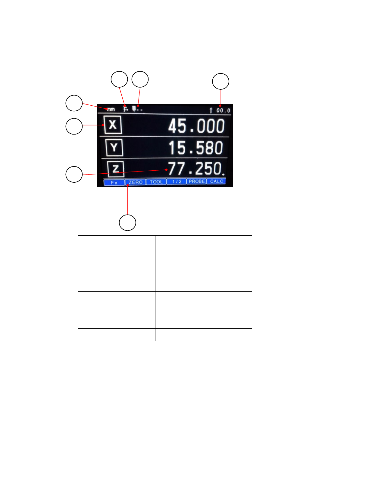
4.8 Screen Layout
Sample screen of EL750 DRO, Labels description is as below.
Labels Description
1
Feed rate
2 Tool No.
3 ABS/ Inc mode
4 Inch / MM
5 Axis Label
6 Display Area
7 Soft key notification
1
2
3
4
5
6
7
EL750
15 | P a g e
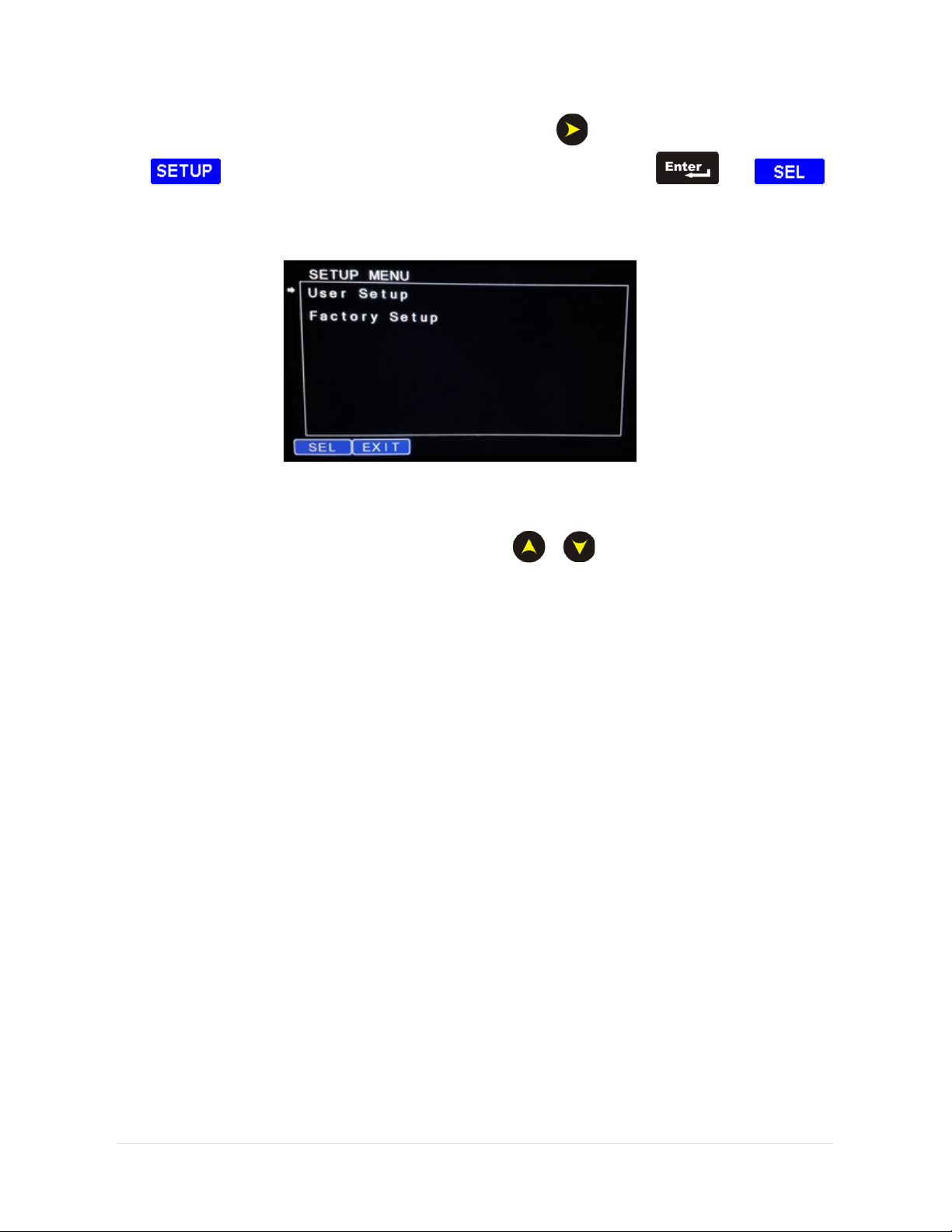
5. Setup
The EL750 setup can be accessed by pressing [ ] key followed by SOFT KEY
{ }. The SETUP mode screen is as shown below. Press [ ] or { }
key to access the setup.
•
Different menus can be navigated using [ ] [ ] keys.
•
Options for each field to be selected are displayed at the SOFT Key labels. A
particular option can be selected using the SOFT key.
Note
: In this manual, following notations will be used
[name] denotes a dedicated key name
{name} denotes a Soft key name

EL750
16 | P a g e
5.1 General Settings:
Sr.
no. User Setup
Parameters Description
1 Sleep Mode Time
(min)
Defines Sleep Time Interval in minutes (5 to 120).
2 Key Beep Enable
To enable or disable keyboard beep ON or OFF.
3 Zero App. Beep En
To enable or disable Zero Approach Beep ON or OFF.
4 Zero App. Tolerance
This sets a tolerance value for Zero Value in Zero approach
modes.
5 Diagnostics
This can be used checking the Keyboard, Encoder, Probe,
and Display as diagnostic tool.
6 Select Axis
This is used for setting axis specific parameters. (Axis
parameters are given below in 5.2 & 5.3)
7
Serial
communication
Enables the user to set the Serial communications
parameters.
8
Recall OEM setting
Recalling OEM settings will reset all the users settings
related to Axis and Auxiliary I/O to Standard OEM setting.
9
Auxiliary Setup
This options enables user to configure auxiliary Inputs &
Outputs
10
Machine Model
User can select Mill or Lathe machine functionality as per
application requirement.
11
Save & Exit
To save the changes and exit from setup.
12
Exit without saving
Exit from setup without saving changes.
5.2 Axis Specific Settings (Linear Type):
1. Scale Resolution:
This option is available for all axes if configured as linear type.
The options available are 0.1 µm, 0.2 µm, 0.5 µm, 1 µm, 2 µm, 5 µm, 10 µm, 20
µm, 50 µm and 100 µm. The default value is
5µm
.
2. Display Resolution:
Option available for all axis, resolution settings available
are 0.1 µm, 0.2 µm, 0.5 µm, 1 µm, 2 µm,
5µm
, 10 µm, 20 µm, 50 µm and 100 µm
if the axis is configured as linear type.
3. Axis Direction:
The counting direction can be set either Left or Right for each
individual axis. The default value is
left
direction.
4. Axis Mode:
The Axis mode can be set either Radius or Diametric for each
individual axis. This is valid only if the DRO is configured as Lathe model. In Mill
model, all axes are forced to RAD mode.
5. Machine Reference:
Keep the encoder position near to the desired reference on
the encoder.

EL750
17 | P a g e
Procedure:-
1) Press { } key in “Machine Ref.” in axis settings. “Homing” Message is
shown on the screen.
2) Pass the reference mark on the encoder. Here the DRO will reset the axis on
the reference mark.
3) Go to the machine reference position and press { }.
6. Zero App. Distance:
Zero Approach Distance is the distance band for zero
approach beep which is used to get operators attention when the axis count is
within the band. There is also a proportional bar graph display that is shown
below the axis display. The default value is “1.000 mm”.
7. Calibrate Axis:
Axis calibration is required to compensate for errors arising due
to wear and tear, encoder misalignment etc. Each axis can be calibrated for
Linear Errors or Segmented errors as applicable. The detailed procedure for
calibration is explained in section 5.4.
8. Apply Compensation:
The type of compensation applied to selected axis is
programmed here. Three options are possible NONE, LEC and SLEC. The
default compensation type is set “NONE”.
9. Soft Limit Settings
: It is used to indicate end point of machine slide. Soft limit
can be turn ON/OFF with desired positive and negative settings
.
The soft limit
working on pure absolute value.
10. Vibration Filter:
In some applications because of vibration or unstable scale the
values of the display could become unstable and unreadable. For example in
grinding application because of the grinding machine vibration the values of the
DRO display can become unstable. It disturbs the user. So this vibration filter
function will help the operator to read the position correctly.

EL750
18 | P a g e
5.3 Axis Specific Settings (Angular Type):
1. Counts per Revolution. (CPR):
This parameter defines the Encoder counts per
rotation. Either the operator can enter this value if this is known or there is an
automatic calibration process for finding the CPR value. In the automatic process,
the user is prompted to pass two reference marks in the same direction. The
DRO counts within them, and sets the CPR value. The default value is 4096.
2. Resolution (Deg.):
This parameter defines the Display resolution in degrees.
The default value is
0.1
degrees. The different display resolutions are available
based on CPR value.
CPR Value Resolution available (degrees)
CPR < 3600 0.5
CPR < 7200 0.5, 0.1
CPR < 36000 0.5, 0.1, 0.05
CPR < 72000 0.5, 0.1, 0.05, 0.01
CPR >= 72000 0.5, 0.1, 0.05, 0.01, 0.005
3. Reference Mode
: This defines which reference mode to select, internal or
external. For internal mode, the DRO uses the encoder reference mark for
referencing. For external mode, the DRO senses an external input (Input 4) first
and then references the DRO on encoder internal reference mark. This mode can
be used where sometimes one machine rotation corresponds to more encoder
rotations due to gear coupling. The default is set to internal.
Note:- External Reference is available only for options DRO
4. Axis Direction
: This defines the counting direction of the encoder, clockwise
(CW) or counter-clockwise (CCW). The default is set to CW.
5. Count Mode
: Under this parameter there are two options:
Rollover: The angle rolls back to zero after 360
°
.
Continuous: The angle continues accumulating after 360
°
.
The default is set to Continuous mode.
6. Machine reference
: There are two types of reference mode, as described In
section 5.3.3
a. Internal reference: -This is similar to that in linear. Only thing the value
is set in degrees.
b. External mode: - The DRO senses an external input first and then
references the DRO on encoder internal reference mark.
7. Display Mode
: The angular axis is configurable for two possible options.
a. DDMMSS – Degrees: Minutes: Seconds (00.00.00).
b. DDDEC – Degrees Decimal (0.0000).
The default mode is DDMMSS.

EL750
19 | P a g e
8. Axis Lock
: Two options are possible for this parameter.
a. Axis Lock ON
b. Axis Lock OFF.
Axis Lock ON prevents the operator from axis setting in absolute mode. Only the
operator can perform referencing. The default value is Axis Lock OFF.
9. Zero App. Angle
: This is similar to the Zero Approach distance in linear mode.
Only the setting is in angular mode. The default value is 10.00.00.
10. Zero App. Tolerance
: This is similar to the Zero approach tolerance in linear
mode. Only the setting is in angular mode. The default value is 0.00.00.
11. Vibration Filter:
In some applications because of vibration or unstable scale the
values of the display could become unstable and unreadable. For example in
grinding application because of the grinding machine vibration the values of the DRO
display can become unstable. It disturbs the user. So this vibration filter function will
help the operator to read the position correctly.
Note
The changes made in the setup mode should be saved by using “Save and Exit”.
Note that the options for each Menu item are displayed on the Soft key label.
User has to press the correct soft key for required settings.
In 4 axis mode, use up key { } to toggle display of Z and U axis in normal
counting mode of DRO.

EL750
20 | P a g e
5.4 Error compensation
These deviations in job accuracies could be the errors in screw pitch of machine or result of
deflection / tilting of axes or encoder installation.
These can be linear or non-linear and can be determined with the help of Standard
measuring system or a high accuracy slip gauge / gauge block.
5.4.1 Error compensation for linear Axis
5.4.1.1 Linear Error Compensation (LEC)
Linear error compensation can be applied, if the results of the comparison with a reference
standard show a linear deviation over the whole measuring length. In this case the error
can be compensated by the calculation of a single correction factor.
Procedure:-
Scroll to “SELECT AXIS” in user setup mode, select the required axis to calibrate using ‘X’,
‘Y’, ‘Z’, ‘U’ soft keys. Following screen will be displayed in axis settings.
•
Error compensation should be done only in case job accuracies are
not as per expectations.
•
If job accuracies are acceptable, the error compensation should not
be performed.
This manual suits for next models
12
Table of contents
Other electronica Industrial Equipment manuals


