Electronicbox D-Box User manual

Installation manual for the Electronicbox, version D
No time for manuals? No problem, this will take only 3 minutes of your time to read it and you will have more fun while the
installation of your new D-Box.
Push button or switch input for the left flashers (orange): You an use this input for a push button or a swit h what
will onne t the input to ground / hassis when pressed. An losed onta t will start the flasher left.
Push button or switch input for the right flashers (purple / violet): You an use this input for a push button or a
swit h what will onne t the input to ground / hassis when pressed. An losed onta t will start the flasher output right.
An emergenc flasher function is a tive by pressing both dire tion buttons. This fun tion is only enabled in the "button
mode" for the flasher se tion.
Push button for the horn function (thin red): The horn will work when the button is pressed and the input able is
onne ted to ground via the button.
Button or Switch input for the headlight (brown): The headlight will toggle between high - and low beam when the
button is pressed and the input able is onne ted to ground.
Button input for the start rela ( ellow): The relay output will swit h the 12 volt for the starter relay when the button is
pressed and the input able is onne ted to ground.
Button input for engine stop (blue): This is the onne tion for the engine stop fun tion. A press on the button will
swit h off the 12 Volt power from the D-Box to the ignition for 2 se onds.
Brake light switch (green): You an onne t your brake light swit h(es) to this able and ontrol your brake light or rear
light with this input.
Ground (black): Just onne t the bla k able dire t to the hassis and make a onne tion from this point to the buttons
of the handle bar. It is important that the handle bar have the same ground onne tion, Otherwise the box might make
some "funny" mistakes due to a poor grounding of the handle bar when a button is pressed.
Output low beam: This is the 12 Volt output for the low beam headlight. However, the light an be swit hed off when
pressing the "start" button in order to have enough energy for the starter (further infos at page 2, "setup").
Output high beam: This is the 12 Volt output for the high beam bulb.
Output horn: This is the 12 Volt output to the horn, what is a tive by a button press. Be careful, this output can control
modern horns with maximum 3 Ampere. Ever current above this value might destro this output.
Flasher outputs left and right: These are the 12 Volt power outputs to the turn signals. However, the flasher frequen y
is independent of the load. So, problems with led flashers are a matter of the past.
Output start rela : This output is onne ted to the start rela and not dire t to the starter. You know that the small D -
Box an not handle dire t 100 Ampere for the starter and will need a starter relay ;-) .
Output brake light / rear light: This output is onne ted to the brake light. You an use this able for the rear light as
well if you swit h on the mode option 5 (see page 2).
12 V Output to ignition: This output is onne ted with the ignition. A press on the stop button will dis onne t the ignition
for 2 se onds.
1 / 2
Flasher control: Some new bikes need a flasher indi ator lamp. Just take simple 2 diodes (1N4007 or similar) and
onne t the athodes, (ring side) together and onne t it to your indi ator lamp. The other sides of the diodes an be
onne ted to the flasher outputs. Thats it...
+ 12 Volt input from ignition lock (big red cable): This is the 12 volt power input for the box and the power outputs.
The outputs of the box are self resettable in the ase of a short ir uit. However, we recommend to wire a 15 Ampere
fuse in the line, ause the temperatures in the ase of a short ir uit will rea h about 120 degree C what might result in
small flaws in the plasti housing and a possible loose of the water prote tion.
Adjustment of the different functions:
The D - Box an be use for the most ir umstan es without any modifi ation on the box. However, you an easily hange
some fun tions in the box without to be a software spe ialist. Just press the "horn" button while swit hing on the ignition
swit h and you are in the "setup mode". An one time emergen y flash will indi ate the "Mode 1". This ist just a small
show fun tion. The flashers will flash 2 times when swit hing on the ignition swit h. Just feel free to press the "right"
button if you like to a tivate this fun tion. Alternatively you an swit h off this fun tion by pressing the "left" button and
you will ome immediately to "Mode 2" what is indi ated with 2 flashes of the dire tion lamps. Feel free to ontinue to
make your personal settings for your bike. All settings are stored in the box after 8 times pressing the "left" or "right"
button. Your done! ...it´s that simple... The D - Box will keep your settings after a power off. However, you an hange
the settings at every time you want. The following options are possible:
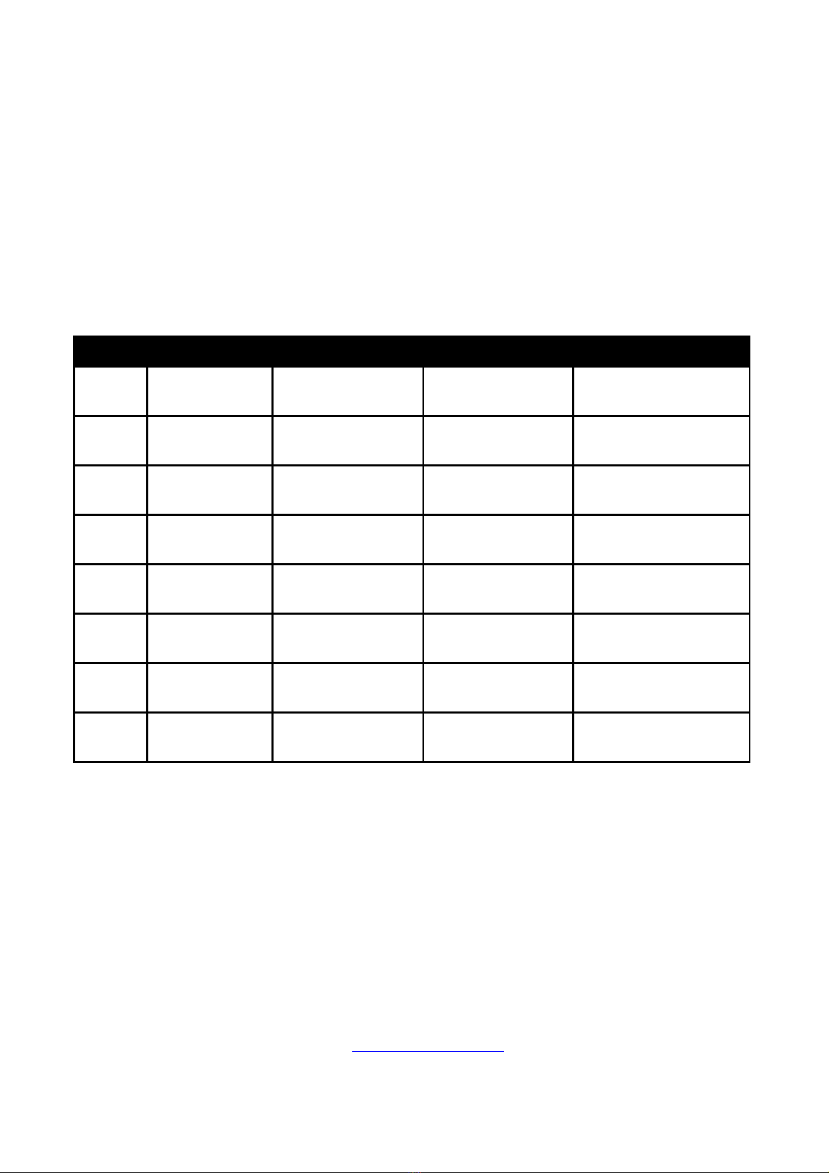
Number of
flashes
Mode Left flasher button Right flasher button Describtion
1 x Show flasher Off On
2 emergen y flashes when
power on the box
2 x Flasher auto off Off On
The flasher will swit h off
after 20 or 40 times
3 x Flasher auto off 20 flashes 40 flashes
Number of repeats when
"Flasher Auto" is on
4 x Low Light On Off
The flashers will glim with
about 25 % when the
flasher fun tion is off
5 x Brake light mode Only brake light
Brake light / rear light
ombination
The rear light will glim with
40 % when the brake light
swit h is not pressed
6 x Start / Stop 1 pushbutton 2 pushbuttons
You an use one or two
buttons for the start and
stop fun tions
7 x
Headlight - swit h
or button Swit h Pushbutton
The box an handle a
headlight swit h or a push
button.
8 x Flasher ontrol Swit h Pushbutton
The flasher an ontrolled
by push button or by a
swit h
Installation:
The power outputs an work with urrents between 3 and 6 Ampere for ea h output. The maximum urrent of the whole
D - Box is 20 Ampere due to the small size of the box. So, please take are that the 12 Volt power to the box is prote ted
with a 15 or 20 Ampere fuse. The ables to the buttons should be more than 10 m away from the ignition and spark plug
ables (if possible) in order to prevent the box against emv disturban es. Otherwise the D - Box might an do some
"funny" unwanted fun tions like hanging the light, swit hing on the flashers, et . It´s also a good idea to use shielded
ables to the push buttons if available. A shielded standard CAT 6 able without onne tors for example should be
available in every lo al omputer shop and the ost is (almost) nothing.
The D - Box was developed for an implemenation in show bikes and ra ing bikes. It should be installed by professional
well trained engineers only. Please he k your lo al regulations regarding the traffi light rules in your ountry before of
the use of the D - Box in your bike. Please be aware that we are not responsible for any hazards, damages or
disadvantages due to the use of the ele troni box. The ele troni box devi es are registered under the number
DE54933725 WEEE as B2C devi e. We also de lare that the D - Box is onform to the CE and ROHS regulations for the
European market.
We tried to keep the fun tions of the D - Box and this manual as simple as possible. If you have any questions while the
installation please don’t hesitate to onta t us at: info@ elektronikbox.de
We wish ou to have a lot of fun with our new D - Box in our bike and
of course alwa s a safel trip!
2 / 2
Popular Motorcycle Accessories manuals by other brands


VIKING BAGS
VIKING BAGS UNIVERSAL LARGE PLAIN SINGLE STRAP... installation instructions

MRA
MRA Sportscreen Mounting instructions

GEARS
GEARS Gen X 4 manual

MadStad Engineering
MadStad Engineering R1200GSA instructions

Denali
Denali LAH.00.10000.B instruction manual

hepco & becker
hepco & becker 7007544 00 01 quick start guide


