manuals.online logo
Brands
  1. Home
  2. •
  3. Brands
  4. •
  5. Denali
  6. •
  7. Motorcycle Accessories
  8. •
  9. Denali LAH.00.10000.B User manual

Denali LAH.00.10000.B User manual

This manual suits for next models

1

Other Denali Motorcycle Accessories manuals

Denali LAH.11.10700 User manual

Denali

Denali LAH.11.10700 User manual

Denali LAH.07.10401 User manual

Denali

Denali LAH.07.10401 User manual

Denali B6 User manual

Denali

Denali B6 User manual

Denali SoundBomb DNL.SB.050 User manual

Denali

Denali SoundBomb DNL.SB.050 User manual

Denali MBK.22.10000 User manual

Denali

Denali MBK.22.10000 User manual

Denali LAH.08.10900 User manual

Denali

Denali LAH.08.10900 User manual

Denali LAH.00.11600 User manual

Denali

Denali LAH.00.11600 User manual

Denali LAH.07.11000 User manual

Denali

Denali LAH.07.11000 User manual

Denali LAH.01.10700 User manual

Denali

Denali LAH.01.10700 User manual

Denali DialDim User manual

Denali

Denali DialDim User manual

Denali LAH.07.11300 User manual

Denali

Denali LAH.07.11300 User manual

Denali T3 User manual

Denali

Denali T3 User manual

Denali LAH.23.10100 User manual

Denali

Denali LAH.23.10100 User manual

Denali D2 User manual

Denali

Denali D2 User manual

Denali LAH.08.10700 User manual

Denali

Denali LAH.08.10700 User manual

Denali LAH.04.10700 User manual

Denali

Denali LAH.04.10700 User manual

Denali LAH.23.10000 User manual

Denali

Denali LAH.23.10000 User manual

Denali ALG.003 User manual

Denali

Denali ALG.003 User manual

Denali MA11729 User manual

Denali

Denali MA11729 User manual

Denali DialDim DNL.WHS.23900 User manual

Denali

Denali DialDim DNL.WHS.23900 User manual

Denali DNL.WHS.12700 User manual

Denali

Denali DNL.WHS.12700 User manual

Denali HMT.08.10300 User manual

Denali

Denali HMT.08.10300 User manual

Denali HMT.07.11000 User manual

Denali

Denali HMT.07.11000 User manual

Denali DialDim DNL.WHS.22800 User manual

Denali

Denali DialDim DNL.WHS.22800 User manual

Popular Motorcycle Accessories manuals by other brands

SRC H-ADV150-04-01AL quick start guide

SRC

SRC H-ADV150-04-01AL quick start guide

DMD P1 owner's manual

DMD

DMD P1 owner's manual

GIVI Airflow AF1110 manual

GIVI

GIVI Airflow AF1110 manual

Suzuki 99143-00A1 000 Series installation instructions

Suzuki

Suzuki 99143-00A1 000 Series installation instructions

Cardo Systems FREECOM 4+ Pocket guide

Cardo Systems

Cardo Systems FREECOM 4+ Pocket guide

Shark S 700 user manual

Shark

Shark S 700 user manual

R&G CR0081 Fitting instructions

R&G

R&G CR0081 Fitting instructions

SRC B-TRK502-01-01-SL quick start guide

SRC

SRC B-TRK502-01-01-SL quick start guide

hepco & becker 6307520 00 01 manual

hepco & becker

hepco & becker 6307520 00 01 manual

HOMCOM AA0-077 user manual

HOMCOM

HOMCOM AA0-077 user manual

hepco & becker 6307558 00 01 manual

hepco & becker

hepco & becker 6307558 00 01 manual

SHOEI JO Instructions for use

SHOEI

SHOEI JO Instructions for use

Wunderkind Custom 106503-F15 Installation and safety

Wunderkind Custom

Wunderkind Custom 106503-F15 Installation and safety

Suzuki 57100-05881 installation instructions

Suzuki

Suzuki 57100-05881 installation instructions

SIKH HELMETS Y-61 quick start guide

SIKH HELMETS

SIKH HELMETS Y-61 quick start guide

Dräger HPS 3500 Instructions for use

Dräger

Dräger HPS 3500 Instructions for use

M-WAVE SKI manual

M-WAVE

M-WAVE SKI manual

Kuryakyn 6212 installation instructions

Kuryakyn

Kuryakyn 6212 installation instructions

manuals.online logo
manuals.online logoBrands
  • About & Mission
  • Contact us
  • Privacy Policy
  • Terms and Conditions

Copyright 2025 Manuals.Online. All Rights Reserved.

DENALI
///////////////////////////////////////////////
LAH.00.10000.B
Instruction Rev00
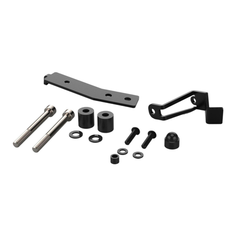
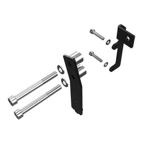
Kit Contents Tools Required
(a) Bracket..............................Qty 2
(b) OD:13mm ID:6mm L:22mm....Qty 2
(c) OD:13mm ID:6mm L:14mm....Qty 2
(d) M8 to M5 Bushing.....................Qty 2
(e) M8 to M6 Bushing.....................Qty 2
(f) M5x60 ISO 7380.................Qty 2
(g) M5x50 ISO 7380.................Qty 2
(h) M5x30 ISO 7380.................Qty 2
(i) M6x60 ISO 7380........................Qty 2
(j) M6x50 ISO 7380........................Qty 2
(k) M6x30 ISO 7380........................Qty 2
(l) M8x12 DIN 7984.........................Qty 2
• 5mm Allen Key
• 4mm Allen Key
• 3mm Allen Key
• 13mm Wrench
• 10mm Wrench
0mm 10 20 30 40 50 60 70 80 90
Thank you for choosing DENALI
We know you would rather be riding your bike than wrenching on it, so we go the extra
mile to make sure our instructions are clear and as easy to understand as possible. If
you have any questions, comments, or suggestions don’t hesitate to give our gear
experts a call at 401.360.2550 or visit DenaliElectronics.com
Please Read Before Installing
DENALI products should always be installed by a qualified motorcycle technician. If
you are unsure of your ability to properly install a product, please have the product
installed by your local motorcycle dealer. DENALI takes no responsibility for damages
caused by improper installation. Caution: When installing electronics is it extremely
important to pay close attention to how wires are routed, especially when mounting
products to the front fender, front forks, or fairing of your motorcycle. Always be sure
to turn the handlebars fully left, fully right, and fully compress the suspension to
ensure the wires will not bind and have enough slack for your motorcycle to operate
properly.
Installation Tips
We strongly recommend using medium strength liquid thread locker on all screws,
nuts, and bolts. It is also important to ensure that all hardware is tightened to the
proper torque specifications as listed in your owner’s manual. For included accessory
hardware please refer to the default torque specifications provided below. Inspect all
hardware after the first 30 miles to ensure proper torque specifications are
maintained.
Hardware Sizing Guide
Not sure what size bolt you have? Use this ruler to measure screws, bolts, spacers, etc.
Remember, the length of a screw or bolt is measured from the start of the “mounting
surface” to the end of the screw, so only include the screw head when measuring
countersunk screws.
M3 10.0 in-lbs - 1.0 Nm
M4 23.0 in-lbs - 2.5 Nm
M5 44.5 in-lbs 3.5 ft-lbs 5.0 Nm
M6 78.0 in-lbs 6.5 ft-lbs 9.0 Nm
M8 - 13.5 ft-lbs 18.0 Nm
M10 - 30.0 ft-lbs 41.0 Nm
M12 - 52.0 ft-lbs 71.0 Nm
in-lbs
ft-lbs NmBolt Size
Universal Pivot Mount
M5, M6 & M8 Mounting Points
Illustration not to scale
0in 1 2 3
a
b
c
e
d
f
ghi
j
k
l
Figure 1
Mounting to an M5 Hole Mounting to an M6 Hole
Mounting to an M8 Hole Attaching the Light Pod
This kit only includes M6 and M5
mounting hardware, but the bracket
(a) will also accept an M8 bolt.
Step One: Adjust the amount of
exposed thread to meet your require-
ments by interchanging different
length M8 bolts and M8 spacers. (NOT
INCLUDED)
Mounting to an M5 Hole
Step One:
If mounting to a M5 hole
press the M8 to M5 adapter bushing
(d) in the 8mm through hole on the
bracket (a).
Step Two: Next adjust the amount of
exposed thread to meet your require-
ments by interchanging the different
length M5 bolts (f, g, h) and spacers (b
& c).
Figure 2
f
g
h
d
b
ca
Mounting to an M5 Hole
Figure 2
f
g
h
d
b
ca
Step Three: Remove the mounting
hinge from your light pod and remove
the orginal M8 hex head bolt.
Step Four: Once removed, use the
included M8x12 bolt (l) to attach the
hinge (l) to the threaded hole in the
light bracket (a).
Step Five: Re attach the assembled
hinge and bracket to your light pod.
Step One:
If mounting to a M6 hole
press the M8 to M6 adapter bushing
(e) in the 8mm through hole on the
bracket (a).
Step Two: Next adjust the amount of
exposed thread to meet your require-
ments by interchanging the different
length M6 bolts (i, j , k) and spacers (b
& c).
Figure 3
Figure 2
Figure 4
M8 mounting hardware
not included with kit
f
g
h
d
b
ca
i
j
k
e
b
ca
a
Figure 5
Example Mounting Bracket
(Included with light)
l
a
Vertical Mounting Example
Note: Be sure that the bracket is only
bolted directly to the frame or frame
elements of the bike. Do not mount to
body clips or plastic fairings that are
not directly bolted to the frame.
Caution: Its extremely important to pay
close attention to how you route the wires.
Step Six: Before operating the motorcycle,
turn the handlebars fully left, fully right and
fully compress the suspension. Confirm that
the lights do not interfere with operation and
that the wires have enough slack to account
for all suspension and steering movement.
Figure 6
Horizontal Mounting Example
Note: Be sure that the bracket is only
bolted directly to the frame or frame
elements of the bike. Do not mount to
body clips or plastic fairings that are
not directly bolted to the frame.
Caution: Its extremely important to pay
close attention to how you route the wires.
Step Six: Before operating the motorcycle,
turn the handlebars fully left, fully right and
fully compress the suspension. Confirm that
the lights do not interfere with operation and
that the wires have enough slack to account
for all suspension and steering movement.
Figure 7