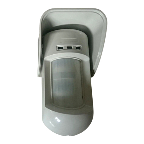
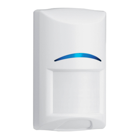
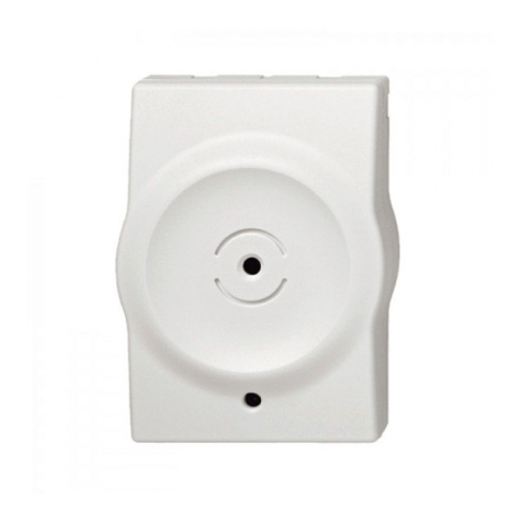
Détecteur Infrarouge Avec Camera 2-Way EL-4755
FRANÇAIS –Introduction:
Le EL-4755 est un détecteur infrarouge avec
caméra intégrée et immunité aux animaux jusqu’à
45kg en option.
Remarque: Jusqu’à 8 détecteurs caméra par centrale.
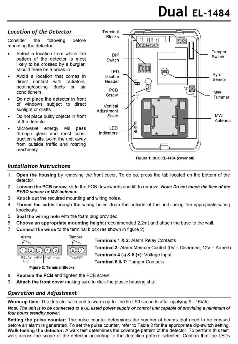
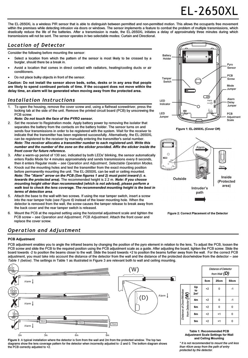
Emplacement du détecteur
•Placez le détecteur dans un lieu de
passage .
•Ne placez pas d'objets encombrants devant
le détecteur.
•Evitez la proximité avec radiateurs,
chauffage / refroidissement des conduits ou
climatiseurs.
•Ne placez pas le détecteur face aux
fenêtres ou à la lumière du soleil.
Enregistrement:
Le détecteur doit être identifié par la centrale :
1. Réglez le système en mode enregistrement.
a. Allez dans le menu principal : Valider
1111et sélectionnez [9]> [1]> [1]
(Programmation> Appareil>Zones)
b. Sélectionnez une zone et appuyez sur
Valider
2. Ouvrez le boîtier
3. Insérer les piles fournies avec le détecteur.
Le détecteur envoi une transmission, et le
système génère une confirmation sonore. Si
aucun son de confirmation ne se fait
entendre, envoyez une autre transmission en
appuyant sur l'autoprotection de l'appareil.
4. Après avoir enregistré le détecteur, continuez
à entrer d'autres paramètres. Il est possible
d'appuyer sur la X pour revenir en arrière et
enregistrer des zones supplémentaires.
Remarque: Pour supprimer un détecteur PIR de la
centrale, se référer au manuel d'installation rapide.
Réglage des paramètres de
l’iConnect:
Comme touts les éléments 2-Way, les paramètres
du EL 4755 ne peuvent être modifié qu'à partir de
la iConnect 2way ou de son Remote Programmer.
Pour plus d'informations reportez-vous à la notice
d'installation.
Allez dans le menu principal et sélectionnez [9]>
[1]> [1]> [11]
Programmation> Appareil> Zones> SENSOR
1. LED: Actif ou Inactif. VALIDER
2. PULSE (Le compteur d'impulsions détermine
laquantité de faisceaux qui doivent être
franchis avant que le capteur génère une
alarme)
3. AL DELAY : signifie RETARD ALARME (Le délai
entre le signalement détections à l'unité
principale)
4. Résolution de la caméra: VGA (640X480), QVGA
(320x240), ou QQVGA (160x120)
5. COULEUR: couleur, ou noir et blanc
6. COMPRESSION: Faible ou Forte
7. FLASH: Actif ou inactive
8. Nombre de Photos
9. Pour usage future
10. Retard de l'image: 0-480 MS (480)
11. CAPTURE D’IMAGE A DISTANCE : Actif ou
inactif.
12. Affectation de zone (détection de mouvement
simple ou détecteurs de fumée et autremis en
relation avec un détecteur image (jusqu’à 4 max
par détecteurs image) déclenche une prise de
vue photo lorsque l’alarme provient de l’une des
zone mise en relation avec un EL 4755.
Les images transmises sont visibles à travers la
interface web:
1. Via un ordinateur ou un smartphone.
2. Rentrez vos codes d’accès.
3. Cliquez sur "Vidéo" pour afficher ou capturer
une image (cette fonction peu être désactiver
pour préserver l’intimité, dans les paramètres
d’enregistrement du détecteur).
Installation:
Remarque:Avant d'installer définitivement le détecteur, testez-le
depuis l’endroit ou vous avez prévu de le fixer. La hauteur
recommandé hauteur est de 2,2 m, voir figures 3 et 4.
1. Percer les trous de fixation du support de fixation
support et le fixer au mur, le cas échéant (Voir
Fig. 1-2)
2. L'autoprotection arrière, (voir la figure 2 position
1).
3. Lorsque le support est retiré de la paroi, la vis
provoque la libération d'autoprotection à se
détacher de la support et l'interrupteur
d'autoprotection arrière est libéré
4. Fixez la vis fournie dans le kit de détection de le
fond du support de montage (voir les figures 1.et
2, la position 2).
Modes de fonctionnement:
Temps de préchauffage: Le détecteur aura besoin
pour se réchauffer pour les 90 premières secondes
après la mise sous tension.
Mode Essai de marche: Un test de marche est
effectué dans le but à «déterminer la distance de
couverture du détecteur (voir figure 3).
Le mode Test annule le temps de retard entre les
détections, vous permettant d’effectuer un test de
marche efficace.
Pour marcher tester le détecteur:
1. Réglez le iConnect 2-Way to Walk mode test
(Touche de raccourci 7> O3> 4).
2. Traversez la portée du détecteur selon la zone
de détection sélectionnée.
3. Assurez-vous que la LED s'active et se
désactive en conséquence. Attendez dix
secondes après chaque détection avant de
continuer le test.
4. Après avoir complété le test de marche de
configurer le système pour mode de
fonctionnement normal.
Pour tester l'appareil photo détecteur:
1. Réglez le iC0nnect 2-Way en mode de test
caméra (Touche de raccourci 7 Service> 03
Test> 5 Photo). Confirmez avec VALIDER.
2. Sélectionnez une zone définie et appuyez sur
VALIDER.
3. Choisir le nombre (de 1 à 9) de photos à
prendre et appuyez sur VALIDER pour
transmettre les clichés.
Indication LED:
L'indicateur LED est allumé chaque fois qu'une
transmission est faite. La LED peut être activée /
désactivée par programmation.
Remplacement de la batterie:
Dans le cas d'une batterie faible (2.5VDC ou moins),
l’état de la batterie du capteur à faible est signalé à
le message de batterie système et faible est affiché.
Pour remplacer la pile:
1. Dévisser le capot du boîtier.
2. Retirer les piles usagées et de les remplacer.
Spécifications techniques:
Antenne: interne
Fréquence: 868,35 MHz *, 433.92MHz
Puissance: 3,6 Vcc AA Batterie au lithium (x 2)
Attention: Danger Incendie, explosion et sévère! ne pas
recharger, démonter ou chauffer à plus 100 ° C (212F).
Consommation de courant: 200mA (avec Flash capture)
42pA (veille)
Capteur électrique: Élément double
Couverture maximale: 14 x 14m
Nombre d'impulsions: 1 ou 2
Indicateur LED: sélectionnable
Compensation de température numérique adaptatif
Immunité RFI: Selon EN 50130-4
Température de fonctionnement: -10 à 55 ° C
Protection incendie: Boîtier en plastique ABS
Dimensions: 110 x 62 x 50mm
Visser recommandée: ST 2.9x22, DIN 7981 (ISO 7049)
* Conforme à la norme EN 50131-2 FO 2 ll classe 2,
Alimentation Type C _V4'V
RTTE Compliance Statement (European version):
Hereby, Electronics Line 3000 Ltd. declares that this equipment is in
compliance with the essential requirements and other relevant
provisions of Directive 1999/5/EC. For the CE Declaration of
Conformity please refer to our website:.
www.electronics-line.com
All data is subject to change without prior notice. In no event shall
Electronics Line be liable for an amount in excess of EL3K.’s
original selling price of this product, for any loss or damage whether
direct, indirect, incidental, consequential or otherwise arising out of
any failure of the product.
Hereby, Electronics Line declares that this detector is in compliance
with the essential requirements and other relevant provisions of
Directive 1999/5/EC.
International Headquarters:
Electronics Line 3000 Ltd.
14 Hachoma St., 75655
Rishon Le Zion, Israel
Tel: (+972-3) 963-7777
Fax: (+972-3) 961-6584
Electronics Line Ltd. 3000 12/2013 5IN1576 B
Legende:
1. Autoprotection et patte
de fixation
2. Trou de fixation pour
les vis
3. Les trous de montage
4. Batterie
5. Antenne
6. Détecteur IRP
7. Indicateur LED
8. Objectif de la ca
9. LED IR
Figure 1 Figure 2


