manuals.online logo
Brands
  1. Home
  2. •
  3. Brands
  4. •
  5. Bircher Reglomat
  6. •
  7. Security Sensor
  8. •
  9. Bircher Reglomat ProLoop Lite User manual

Bircher Reglomat ProLoop Lite User manual

1







85
22.5
92
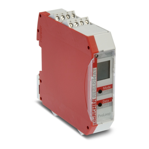
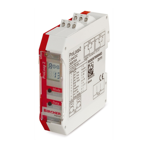
ProLoop Lite
Loop detector for industrial doors and gates and car parks
Translation of the original instruction
General
1Safety instructions
3Connect electrical equipment
2Mechanical mounting in the switch cabinet
ENGLISH
354822B
06/16
i
Information – light emitting diode
LCD display
“Mode” key
“Data” key
Connecting terminals
Type plate
– These devices and their accessories may only be operated in accordance
with the operating instructions (intended use).
– These devices and their accessories may only be placed in operation by
trained and qualied personnel.
– These devices may only be operated with the operating voltages and
parameters intended for them.
– If malfunctions occur that cannot be eliminated, place the device out of
operation and send it in for repair.
– These devices may only be repaired by the manufacturer. Tampering and
alterations are not permitted. This will invalidate all guarantee and war-
ranty claims.
The ProLoop Lite is mounted in the switch cabinet on a 35 mm H-rail in accordance with EN 50022. The terminals can be plugged in and coded.
The loop connection wiring to a loop detector must be twisted at least 20 times per meter.
Please wire the device according to the wiring diagram.
Ensure correct assignment of the terminals and that the power supply is right in accordance with the type plate on the device.
Power supply Loop connection
1-channel device
Loop connection
2-channel device
Output 1 Output 2
˜⁄
+
˜⁄
−
A1
A2
L3
L4
L3
L4
L5
L6
1
2
14
11
12
no
nc
common
24
21
22
no
nc
common
4Value and parameter setting options
General
The settings of the ProLoop Lite devices in this chapter are depicted and explained using the 1-loop device.
The settings for loop 2 of a 2-loop device should be made using the corresponding method.
3.1 Terminal connection diagram
2
4.1 Value and parameter setting options
4.2 Basic functions of output relay status 0(setting, see table 4.8)
4.3 Time functions 1, time unit 2and time factor 3 (settings, see table 4.8)
4.4 Sensitivity 4(setting, see table 4.8)
4.5 Automatic sensitivity boost ASB S(setting, see table 4.8)
4.6 Frequency 6(setting, see table 4.8)
4.7 Switching from operating to conguration mode
Standard display
1-loop device
Standard display
2-loop device
112
Explanation of the LEDs
Info
Red + Green Start-up phase
conguration
Green Operation
Green ashing Output 1 or / and
2 activated
Flashing red Error
Explanation of the LCD display
Loop 2
Loop 1
Function
Example:
Time
function set
12
Example:
Parameter
“h” set
Parameter Loop unactivated Loop activated Fault
1Door and gate
2Barrier
3Quiescent
current
Activation of the
loop pulls the relay
on; the relay drops
off when the loop
is exited. t = typically ms or s
Switch-on delay:
When the loop is
activated, the relay is
pulled on after the time t
and drops off when the
loop is exited.
t
t = typically ms or s
Switch-o delay:
When the loop is
activated, the relay is
pulled on drops off after
time t tafter the loop is
exited.
t
t = typically ms or s
Activation pulse:
When the loop is
activated, the relay
is pulled on and
drops back off
after time t.
t
t = typically ms or s
Exit pulse:
When the loop is exited,
the relay is pulled on and
drops back off after time
t.
t
t = typically ms or s
Maximum presence:
When the loop is
activated, the relay is
pulled on and drops back
off when exited, but not
later than after time t.
t
t = typically ms or s
The sensitivity Sof the loop detector can be adjusted in 9 steps:
S1 = lowest sensitivity
(➝much metal, low recognition distance)
S9 = highest sensitivity
(➝ little metal, large recognition distance)
S4 = factory setting
ASB (= Automatic Sensitivity Boost).
ASB is required in order to be able to detect trailer drawbars after activation.
Four different frequencies F1, F2, F3 and F4 can be set. This helps to prevent crosstalk with adjacent loops. Factory setting: F4.
1-loop device
Display after
start-up:
1Touch the «Mode» button
once to change to configura-
tion mode
Mode 1
2-loop device
Display after
start-up:
12Touch the «Mode» button
once to change to configura-
tion mode
Mode 1
Loop 1 is
selected
Mode 2
Loop 2 is selected
(Back to automatic mode: Press and hold Mode button > 1 second)
Loop
Relay
Loop
Relay
Loop
Relay
Loop
Relay
Loop
Relay
Loop
Relay
3
Table Settings Button
operation
parameter
Data Data Data Data Data Data
Function LCD
Display
Button operation
functions
AOperating
mode
1
Mode
Operating mode 1
0Basic function 1
Mode
Door and gate* 1Barrier
1
Quiescent current 1
1Time function 1
Mode
∞* 1Switch-on delay
t
1
Switch-off delay
t
1Loop activation
pulse
t
1Loop exit pulse
t
1Maximum
presence
t
1
2Time unit
1
Mode
With time
function th (∞),
this display
does not appear
0.1 second 11 second*
1
1 minute 11 hour 1
Note:
Time unit multiplied by time factor
gives the set time.
3Time factor 1
Mode
With time
functionth(∞),
this display
does not appear
1 * 1
Set value between 1 and 99 by touching or holding the «Data» button
4Sensitivity 1
Mode
S
Sensitivity =
responsiveness
4 * 1
Set value between 1 (lowest ) and 9 (highest sensitivity) by touching or holding the “Data” button
5Automatic
sensitivity
boost ASB
1
Mode
ASB stands for
Automatic
Sensitivity
Boost
Switched off* 1Switched on 1
6Frequency 1
Mode
Frequency F1
1
Frequency F2
1
Frequency F3 1Frequency F4* 1
*Factory setting
Loop
Relay
Loop
Relay
Loop
Relay
Loop
Relay
Loop
Relay
Loop
Relay
4.8 Conguration mode
Note on 2-loop device: For each function after Loop 1 is set, the parameters of Loop 2 are set (perform settings similarly).
4
5Error display
6Reset
7Technical data
8EC Declaration of Conformity
9Contact
Manufacturer: Bircher Reglomat AG, Wiesengasse 20, CH-8222 Beringen
Following directives have been observed: RoHS 2011/65/EU, RED 2014/53/EU
Product variants: ProLoop Lite 1.x, ProLoop Lite 2.x
Bircher Reglomat AG
Wiesengasse 20
CH-8222 Beringen
www.bircher-reglomat.com
When an error occurs, the operating mode “A” and the error display “E” are shown alternatingly.
The LED changes to ashing red.
Mode
2 seconds Reset 1 (recalibration)
The loop(s) is/are recalibrated.
Power supply
voltage/
power consumption
24 VDC 24 VDC -10% to +20%,
max. 1.5 W
230 VAC 230 VAC ± 10%, 50 Hz,
max. 2.9 VA
Loop inductiveness Max. 20 to 1000 µH
Ideally 80 to 300 µH
Loop power line For 20-40 µH: max. 100 m with 1.5 mm2
For >40 µH max. 200 m with 1.5 mm2
Min. twisting 20 times per metre
Loop resistance < 8 ohms with connection wire
Output relay (loop) Max. 240 VAC; 2 A / 30 VDC; 1 A; AC-1
Dimensions 22.5 x 92 x 85 mm (W x H x D)
Housing mounting Direct DIN rail mounting
Connection type Screw-in terminals
Protection class IP 20
Operating
temperature
-20°C to +60°C
Storage
temperature
-40°C to +70°C
Air humidity < 95% non-condensing
Danish seller:
Swissdoor ApS
Stenhuggervej 2
DK-5471 Soendersoe
Denmark
Tel.: +45 86 28 00 00
[email protected]
www.swissdoor.dk

Other Bircher Reglomat Security Sensor manuals
Bircher Reglomat ProLoop User manual

Bircher Reglomat

Bircher Reglomat ProLoop User manual

Bircher Reglomat Herkules 2E User manual

Bircher Reglomat

Bircher Reglomat Herkules 2E User manual

Bircher Reglomat Merkur 2 Series User manual

Bircher Reglomat

Bircher Reglomat Merkur 2 Series User manual

Bircher Reglomat RBM 2 User manual

Bircher Reglomat

Bircher Reglomat RBM 2 User manual

Bircher Reglomat ESM User manual

Bircher Reglomat

Bircher Reglomat ESM User manual

Bircher Reglomat PrimeTec B User manual

Bircher Reglomat

Bircher Reglomat PrimeTec B User manual

Bircher Reglomat DI1-Pro V2 User manual

Bircher Reglomat

Bircher Reglomat DI1-Pro V2 User manual

Bircher Reglomat Herkules 2 User manual

Bircher Reglomat

Bircher Reglomat Herkules 2 User manual

Bircher Reglomat ProLoop User manual

Bircher Reglomat

Bircher Reglomat ProLoop User manual

Bircher Reglomat EsGate 2 User manual

Bircher Reglomat

Bircher Reglomat EsGate 2 User manual

Bircher Reglomat MERKUR User manual

Bircher Reglomat

Bircher Reglomat MERKUR User manual

Bircher Reglomat US beam Supplement

Bircher Reglomat

Bircher Reglomat US beam Supplement
Bircher Reglomat EasyMotion User manual

Bircher Reglomat

Bircher Reglomat EasyMotion User manual

Bircher Reglomat RK 31C-PWH User manual

Bircher Reglomat

Bircher Reglomat RK 31C-PWH User manual

Bircher Reglomat Jupiter User manual

Bircher Reglomat

Bircher Reglomat Jupiter User manual

Bircher Reglomat Swissdoor PrimeMotion B User manual

Bircher Reglomat

Bircher Reglomat Swissdoor PrimeMotion B User manual

Bircher Reglomat MERKUR SE User manual

Bircher Reglomat

Bircher Reglomat MERKUR SE User manual

Bircher Reglomat Reflex ES User manual

Bircher Reglomat

Bircher Reglomat Reflex ES User manual

Bircher Reglomat PrimeMotion B User manual

Bircher Reglomat

Bircher Reglomat PrimeMotion B User manual

Bircher Reglomat ProLoop 2 User manual

Bircher Reglomat

Bircher Reglomat ProLoop 2 User manual

Bircher Reglomat Hercules 2 User manual

Bircher Reglomat

Bircher Reglomat Hercules 2 User manual

Bircher Reglomat PrimeTec B User manual
Bircher Reglomat

Bircher Reglomat PrimeTec B User manual
Bircher Reglomat PrimeScan B Supplement

Bircher Reglomat

Bircher Reglomat PrimeScan B Supplement

Bircher Reglomat PrimeMotion C User manual

Bircher Reglomat

Bircher Reglomat PrimeMotion C User manual

Popular Security Sensor manuals by other brands

System Sensor JTWB-BCD-5151EIS Installation and maintenance instructions

System Sensor

System Sensor JTWB-BCD-5151EIS Installation and maintenance instructions

Linxon LX218 operating manual

Linxon

Linxon LX218 operating manual

IR-Tec DUOGUARD DP-250 installation instructions

IR-Tec

IR-Tec DUOGUARD DP-250 installation instructions

Pepperl+Fuchs NBB10-30GS50-Z4L-V1-3G-3D instruction manual

Pepperl+Fuchs

Pepperl+Fuchs NBB10-30GS50-Z4L-V1-3G-3D instruction manual

Optex CDX Series installation manual

Optex

Optex CDX Series installation manual

SPY 785 operating instructions

SPY

SPY 785 operating instructions

Siemens Cerberus DOTE1152 Technical description

Siemens

Siemens Cerberus DOTE1152 Technical description

Genesis ED1 Installation and operating manual

Genesis

Genesis ED1 Installation and operating manual

Reno A&E U-1400 Operation manual

Reno A&E

Reno A&E U-1400 Operation manual

Amprobe RLD-1 user manual

Amprobe

Amprobe RLD-1 user manual

Nortech PD130 user manual

Nortech

Nortech PD130 user manual

Megger VF5 user guide

Megger

Megger VF5 user guide

ZyAura ZGw19 operating instructions

ZyAura

ZyAura ZGw19 operating instructions

WOOX R7046 quick guide

WOOX

WOOX R7046 quick guide

Hytronik HMW31 Installation and instruction manual

Hytronik

Hytronik HMW31 Installation and instruction manual

autosen AO701 operating instructions

autosen

autosen AO701 operating instructions

DSC LC-100-PI installation manual

DSC

DSC LC-100-PI installation manual

Optex FX-50QZ installation instructions

Optex

Optex FX-50QZ installation instructions

manuals.online logo
manuals.online logoBrands
  • About & Mission
  • Contact us
  • Privacy Policy
  • Terms and Conditions

Copyright 2025 Manuals.Online. All Rights Reserved.