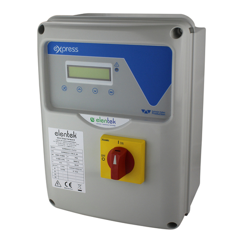
Elentek SMART PRO User manual

SMART PRO - User Manual
ELECTRICAL PANEL FOR 1 OR 2 MOTORS


III
CONTENTS
1. INTRODUCTION......................................................................................................5
2. WARNINGS ............................................................................................................6
3. OVERVIEW .............................................................................................................7
4. INSTALLATION........................................................................................................9
5. LIGHT INDICATORS AND COMMANDS..................................................................10
6. MAIN BOARD INPUTS AND OUTPUTS...................................................................11
7. EXPANSION INPUTS .............................................................................................13
7.1 RS485 expansion............................................................................................................13
7.2 Voltage-free contact output expansion .........................................................................13
7.3 Probe input expansion for motor start ..........................................................................13
7.4 Probe input expansion for water seepage into oil chamber ..........................................13
7.5 Buffer battery device expansion ....................................................................................13
7.6 Bluetooth-WIFI expansion .............................................................................................14
8. MOTHERBOARD DIP-SWITCH SETTINGS ...............................................................15
8.1 DIP-SWITCH 1 - level alarm signalling from probe input...............................................15
8.2 DIP-SWITCH 2 - Ammeter trip delay...............................................................................15
8.3 DIP-SWITCH 3 - Klixon input deactivation......................................................................16
8.4 DIP-SWITCH 4 - Alarm reset enable from motor Klixon .................................................16
8.5 DIP-SWITCH 5 - Filling/Emptying mode probe input......................................................16
8.6 DIP-SWITCH 6 - Self-holding enable (start/stop floats)..................................................17
8.7 DIP-SWITCH 7 - Delayed board activation enable on mains power return ....................17
8.8 DIP-SWITCH 8 - Motor switching module enable...........................................................18
9. DIP-SWITCH SETTINGS DISPLAY............................................................................19
9.1 DIP-SWITCH 1 - NO/NC (G/P1 - G/P2 - G.A.) Input reversal ...........................................19
9.2 DIP-SWITCH 2 - Phase sequence control exclusion ........................................................19
9.3 DIP-SWITCH 3 - Self-test enable.....................................................................................19
9.4 DIP-SWITCH 4 - Manual push or impulse key.................................................................20
10. TRIMMER SETTINGS.........................................................................................21
10.1 TRIMMER SENS. PROBE - Probe sensitivity ....................................................................21

IV
10.2 TRIMMER MIN - Activation on minimum current ..........................................................21
10.3 MAX TRIMMER - Activation on current overload...........................................................22
11. BOARD SPECIFICATIONS ..................................................................................23
12. STANDARD WIRING DIAGRAMS.......................................................................24
12.1 SMART PRO Single phase (230V) wiring diagram..........................................................24
12.2 SMART PRO Three phase (400V) wiring diagram ..........................................................25
13. EXPANSION WIRING DIAGRAMS......................................................................26
13.1 PRO-RS485 expansion....................................................................................................26
13.2 Voltage-free contact expansion PRO-6DO.....................................................................26
13.3 PRO-SL probe input expansion.......................................................................................27
13.4 PRO-SL H20 probe input expansion ...............................................................................27
14. WIRING DIAGRAMS .........................................................................................28
14.1 SMART PRO LED 1 MONO..............................................................................................28
14.2 SMART PRO LED 2 MONO..............................................................................................29
14.3 SMART PRO LED 1 TRI....................................................................................................30
14.4 SMART PRO LED 2 TRI....................................................................................................31
15. RS485 MODBUS ADDRESSES............................................................................32
16. SIZE TABLE .......................................................................................................35
17. TROUBLESHOOTING.........................................................................................36

5
1. INTRODUCTION
This manual must always accompany the relevant equipment and be kept at an accessible location
for consultation by qualified technicians assigned for operation and maintenance of the system.
The installer/user is strongly recommended to carefully read all instructions and information in this
manual before using the product, in order to avoid damage or improper use of the unit, which would
also render the warranty null and void.
Before operating the equipment, carefully read the manual and follow all instructions provided.
The information and instructions in this manual refer to the standard use of this product; in the
event of special circumstances, functions or applications not described in this document, please
contact our service centre for assistance.
If technical assistance or spare parts are required, when contacting the manufacturer always specify
the identification code of the model and construction number as stated on the data plate.
Our service centre is available for any requirement or clarification.
On receiving the goods, carry out an inspection immediately to ensure that the equipment has not
been damaged during transport. If defects are found, the client should promptly notify, within 5 days
of receiving the goods, our retailer or in the event of direct purchases, the manufacturer's service
centre.
N.B. the information provided in this manual is subject to modifications without
notice. The manufacturer shall not be held liable for any damage caused in relation
to the use of these instructions, as they are provided for guidance only. Note that
failure to observe the instructions provided in this manual may cause physical injury
or damage to property.
It is understood that compliance with local provisions and/or statutory regulations in force is
compulsory.

6
2. WARNINGS
The electrical panel must be used exclusively for the purpose and function as specified in design.
Any other application or use is to be considered improper and therefore hazardous.
In the event of a fire in the place of installation or the surrounding area, avoid using water jets and
use appropriate extinguishing equipment and means (powder, foam, carbon dioxide).
Install the equipment far from heat sources and in a dry and sheltered location according to the
specified protection rating (IP).
The installation of a safety device is recommended to protect the panel power line in compliance
with current electrical safety standards.
Before performing any work on the electrical panel or system, disconnect the electrical power
supply.
No parts of the panel should be removed without an official authorisation from the manufacturer:
any tampering with or changes to the unit will render all terms of the warranty null and void.
All installation and/or maintenance operations must be performed by a specialised technician who
is fully aware of the currently applicable safety standards.
Ensure that the installation is connected to an efficient earthing system.
After completing the electrical wiring, check that all electrical panel settings are correct to avoid
automatic start-up of the electric pump.
The manufacturer declines all liability in the event of the following:
-Incorrect installation;
-Use by personnel not adequately trained in the correct use of the panel;
-Serious failure to perform scheduled maintenance;
-Use of non-original spare parts or parts not model-specific;
-Unauthorised modifications or interventions;
-Partial or total failure to observe instructions.

7
3. OVERVIEW
•Single-phase board power supply 100-240Vac 50/60Hz;
•Three-phase board power supply 310-450Vac 50/60Hz;
•Electronic board own consumption 3W;
•G/P1 and G/P2 normally open inputs for motor start-up;
•C-MIN-MAX inputs for single-pole level probes;
•T1 and T2 normally closed inputs for motor thermal switch (Klixon);
•G.A. normally open input for alarm activation;
•Digital outputs for motor overcurrent alarms, from G.A. input and probe input;
•Cumulative alarm output with voltage-free contacts (NC-C-NO resistive load - 5A / 250V);
•Cumulative alarm output, live (12Vcc / 100mA);
•DIP-SWITCH 1 - Level alarm signalling from probe input;
•DIP-SWITCH 2 - Ammeter activation delay of 5/10 seconds;
•DIP-SWITCH 3 - Alarm output setting;
•DIP-SWITCH 4 - Alarm reset enable from motor Klixon;
•DIP-SWITCH 5 - Filling/emptying or pressurization mode;
•DIP-SWITCH 6 - Self-holding enable (start/stop floats);
•DIP-SWITCH 7 - Delayed board activation enable on mains power return;
•DIP-SWITCH 8 - Motor switching enable;
•DIP-SWITCH 1 display - Inputs reversal NO/NC (G/P1 - G/P2 - G.A.);
•DIP-SWITCH 2 display - Phase sequence control exclusion;
•DIP-SWITCH 3 display - Self test enable;
•DIP-SWITCH 4 display - Fixed/pulse manual;
•AUTOMATICO key;
•0 ‘standby’ key;
•MANUAL key;
•Green led: power ON / failure or incorrect phase sequence
•Green led: automatic mode activated;
•Green led: motors activated;
•Red led: min/max level or GA input alarm;
•Red led: motor overload alarm/minimum current alarm;
•Red led: motor Klixon activation alarm;
•Missing or incorrect phase sequence check on power supply input;
•Protections of auxiliary circuits and motor with fuses;
•Door lock general disconnect switch (if any);

8
•Provision for start-up capacitors, single phase version (not included);
•Box in ABS, IP55;
•Ambient temperature: -5/+40 °C;
•Altitude a.s.l. 2000 m;
•Relative humidity 50% at 40 °C (condensate free).
CAUTION!
For further technical data, please refer to the nameplate on the control
panel.
General characteristics may vary if accessories are added to the standard product.
The addition of accessories may result in changes to the above description.

9
4. INSTALLATION
Ensure that the mains power supply specifications match the voltage specified on the data plate
of the electrical panel and connected motor, then provide an earthing connection before all other
wiring.
The power line must be protected by a residual current circuit breaker.
Tighten the electrical cables on the corresponding terminals using a suitable tool correctly sized to
avoid the risk of damaging the fixing screws. Be extra careful if using an electric screwdriver.
The electrical panel is designed for wall-mounting using screws and plugs in the pre-drilled holes at
the corners of the enclosure, or brackets where available.
Install the equipment in areas compliant with the protection rating and ensure that the box is kept
intact when drilling the holes for fitting the cable clamps.
Avoid the use of multicore cables where there are wires connected to inductive loads and power
cables and signal cables such as probes and digital inputs.
Keep connection cables as short as possible, preventing any twisting of cables which may be harmful
due to inductive effects on the electronic equipment.
All wires used in the wiring must be suitably sized to withstand the power load.

10
5. LIGHT INDICATORS AND COMMANDS
STEADY green led: mains power ON
FLASHING green led: failure or incorrect phase sequence
Green led OFF: device not powered;
STEADY green led: electric pump operating
QUICK FLASHING green led (1 second): minimum current control enabled
Green led OFF: electric pump on standby
STEADY red led: motor thermal switch trip
SLOW FLASHING red led: minimum current alarm
QUICK FLASHING red led: water seepage in oil chamber
QUICK FLASHING red led (1 second) minimum current control disabled
STEADY red led: level alarm from sensor input
FLASHING red led: alarm from GA input
STEADY red led: motor overtemperature alarm with manual reset
FLASHING red led: motor overtemperature alarm with automatic reset
AUT key: automatic mode
AUT key for alarm reset (when pressed for 2 seconds)
STEADY green led: automatic mode active
SLOW FLASHING green led: motor current calibration mode (Min/Max)
Green led OFF: automatic mode disabled
0 key: motor operation stop or standby
MAN key: manual mode

11
6. MAIN BOARD INPUTS AND OUTPUTS
T1
Normally open input for motor 1 Klixon (thermal switch).
Jumper if not using this input.
T2
Normally open input for motor 2 Klixon (thermal switch).
Jumper if not using this input.
C - MIN - MAX
Inputs for single-pole level probes
Input for minimum level float (connection between C and MAX).
Input for general enabling (connection between C and MAX).
Jumper C and MAX if not using this input.
G/P1
Input for motor 1 activation.
When rotation operation is active, the first alternating motor will start
each time the input is opened and closed.
G/P2
Input for motor 2 activation.
When rotation operation is active, each time the input is opened and
closed it will start both motors regardless of the status of G/P1 input.
G.A.
Input for alarm activation.
OUT ALARM
(NC - C - NO)
Cumulative alarm output with voltage-free contacts (resistive load - 5A /
250V) for:
-Probe level alarm (DIP SWITCH 1 settable).
-G.A. Input alarm.
-Minimum motor current alarm.
-Motor overcurrent alarm.
-Motor overtemperature alarm.
-Sequence or missing phase alarm.
-Max level alarm.
BUZZ +/-
Alarm output, live (12Vcc / 100mA);

12
OUT MOTOR
SINGLE PHASE:
•L/S - Motor phase
•N/R - Motor idle
•AVV - Start with on board capacitor
THREE PHASE:
•T1 (contactor) - Motor phase U
•T2 (contactor) - Motor phase V
•T3 (contactor) - Motor phase W
Earthing.

13
7. EXPANSION INPUTS
7.1 RS485 expansion
A(-) –B(+)
Module for RS485 communication standard with MODBUS protocol
7.2 Voltage-free contact output expansion
O1 –O6
Module for 6 digital outputs 300mA 35V max for the signalling of:
-O1: Motor 1 run
-O2: Motor 2 run
-O3: Overcurrent protection for motor 1
-O4: Overcurrent protection for motor 2
-O5: GA active alarm
-O6: Probe/G.MIN active alarm
7.3 Probe input expansion for motor start
C –S1 ÷ S4
PRO-SL input module:
-C –MIN –MAX (on main board): motor 1 start
-C (expansion): common
-S1 –S2 (expansion): probe for motor 2 start control
-S3 –S4 (expansion): probe for max. level signalling
7.4 Probe input expansion for water seepage into oil chamber
C –S4 ÷ S5
RL-H2O input module:
-C: common (to be connected to earthing potential)
-S4 (expansion): probe for motor 1 control
-S5 (expansion): probe for motor 2 control
7.5 Buffer battery device expansion
PRODBT module for connection of 6V 1,2Ah buffer battery for maintaining
control of alarm float and for signalling mains power supply failure

14
7.6 Bluetooth-WIFI expansion
Allows the panel to be connected to any device via Wi-Fi or Bluetooth to
use the Elentek APP

15
8. MOTHERBOARD DIP-SWITCH SETTINGS
Set DIP-SWITCHES with the panel switched off.
8.1 DIP-SWITCH 1 - level alarm signalling from probes input
OFF
Level alarm signalling from probe input disabled
ON
Level alarm signalling from probe input enabled
DIP-SWITCH 1 enables level alarm signalling from probe input or minimum level float (C-MIN-
MAX input).
In the OFF position, an input status change does not cause any alarm signal.
In the ON position, an input state change - depending on the emptying or filling function - leads
to the signalling of an alarm on the panel and the activation of the voltage-free contact alarm
output and voltage alarm output.
8.2 DIP-SWITCH 2 - Ammeter trip delay
OFF
Delay of motor ammeter activation by 5 seconds
ON
Delay of motor ammeter activation by 10 seconds
DIP-SWITCH 2 is used to select the thermal switch activation delay time of 5 or 10 seconds.
The setting of this parameter prevents activation of the motor thermal switch during motor start-
up, thereby avoiding a start-up current.
In the OFF position, the ammeter trip delay at motor start is 5 seconds.
In the ON position, the ammeter trip delay at motor start is 10 seconds.

16
8.3 DIP-SWITCH 3 - Klixon input deactivation
OFF
Klixon thermal switch enabled
ON
Klixon thermal switch disabled
DIP-SWITCH 3 enables the Klixon input for motor overtemperature control.
In the OFF position, Klixon inputs are enabled.
In the ON position, Klixon inputs are disabled.
If inputs are disabled and motors do not have a thermal switch, there is no need to jumper them.
8.4 DIP-SWITCH 4 - Alarm reset enable from motor Klixon
OFF
Motor overtemperature alarm with manual reset
ON
Motor overtemperature alarm with automatic reset
DIP-SWITCH 4 enables selection of whether the motor overtemperature alarm activated by the
T1 and T2 Klixon inputs must be reset manually, by keeping the AUT key pressed, or in automatic
mode.
In the OFF position, reset is manual on motor overtemperature.
In the ON position, reset is automatic on motor overtemperature.
8.5 DIP-SWITCH 5 - Filling/Emptying mode probe input
OFF
Level probe operation in filling mode only
ON
Level probe operation in emptying or pressurization mode only
DIP-SWITCH 5 enables selection of whether to use the probe input C-MIN-MAX in emptying or
filling mode.
In the OFF position, the input is used to enable the system when water is not present. The C-MIN-
MAX input must be open to enable the system. If a float-type on/off control is used, use C-MAX
input.
In the ON position (emptying or pressurization), the input is used to enable the system when
water is present. The C-MIN-MAX input must be closed to enable the system. If a float-type on/off
control is used, use C-MAX input.
NB: If no minimum level control is used, jumper the C-MAX input.

17
8.6 DIP-SWITCH 6 - Self-holding enable (start/stop floats)
OFF
Self-holding disabled (start/stop floats)
ON
Self-holding enabled (start/stop floats)
DIP-SWITCH 6 is used to activate the self-holding function for start/stop floats for wastewater
emptying.
For this setting, the stop float must be connected to the C-MAX input and the start float to G/P1
and G/P2.
In the OFF position, the operation with float self-holding is disabled.
In the ON position, the operation with float self-holding is enabled.
NB: Do not activate on pressurization plants. Activate on emptying mode only if C-MIN-MAX
input is used with floats or level probes.
8.7 DIP-SWITCH 7 - Delayed board activation enable on mains power return
OFF
Deactivation of board delay on mains power return
ON
Activation of board delay on mains power return
DIP-SWITCH 7 is used for delayed board activation on mains power return.
In the OFF position, the board will be activated immediately on power return.
In the ON position, the board will be activated 30 seconds after power return.
N.B. after a power supply failure, the board is reactivated maintaining the previous AUT -0 MAN
status.

18
8.8 DIP-SWITCH 8 - Motor switching module enable
OFF
Switching module deactivation
ON
Switching module activation
DIP-SWITCH 8 enables automatic switching of the motors.
In OFF position, G/P1 input directly and independently controls motor output 1 and G/P2 directly
and independently controls motor output 2.
In the ON position, this function means that on each call from G/P1 the motor outputs are
activated alternately and, in the event of a simultaneous call from G/P2 input , both motors will
be operated. When enabled, the switching module alternates the motor on each call from G/P1
input and also switches motors in the event of:
•Current overload of a motor
•Motor set to standby
•Lack of water on subsequent automatic reset

19
9. DIP-SWITCH SETTINGS DISPLAY
Set DIP-SWITCHES with the panel switched off.
9.1 DIP-SWITCH 1 - NO/NC (G/P1 - G/P2 - G.A.) Input reversal
OFF
Normally open inputs.
ON
Normally closed inputs.
DIP-SWITCH 1 allows to invert the enabling of digital inputs G/P1 - G/P2 - G.A.
In the OFF position, normally open inputs enable the system to close the contact.
In the ON position, normally closed inputs enable the system to open the contact.
9.2 DIP-SWITCH 2 - Phase sequence control exclusion
OFF
Missing or incorrect phase sequence check enabled.
ON
Missing or incorrect phase sequence check disabled.
DIP-SWITCH 2 disables the missing or incorrect phase sequence check at the panel input.
In the OFF position, power phase fault monitoring is enabled.
In the ON position, power phase fault monitoring is disabled.
NB: this check is only available in three-phase version.
9.3 DIP-SWITCH 3 - Self-test enable
OFF
Motor self-test disabled
ON
Motor self-test enabled
DIP-SWITCH 3 enables motor self-test.
In the OFF position, self-test is disabled.
In the ON position, self-test is enabled.
Self-test has a fixed, non-adjustable time and will enable the pump, or pumps depending on the
panel model, for 2 seconds every 48 hours.
A pump self-test can only be activated if the Automatic function of the panel is enabled.

20
9.4 DIP-SWITCH 4 - Manual push or impulse key
OFF
Manual push key.
ON
Manual impulse key.
DIP-SWITCH 4 sets operation of the manual key.
In the OFF position, the manual key enables the motor by holding the key down; when it is
released, the motor stops.
In the ON position, the manual key enables the motor at the first impulse and stops the motor at
the next impulse.
This manual suits for next models
14
Table of contents
Other Elentek Control Panel manuals
Popular Control Panel manuals by other brands
Elframo
Elframo VE quick start guide

IPC
IPC Golden-H instruction manual
Chamberlain
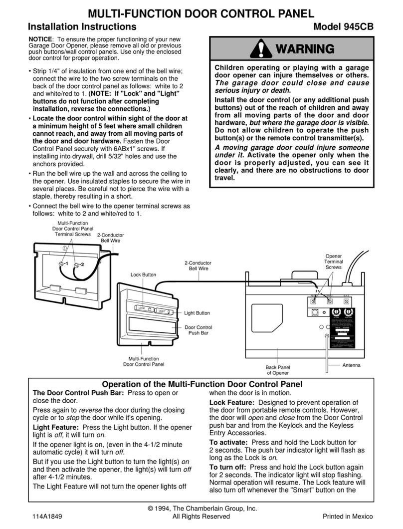
Chamberlain 945CB installation instructions

Rosslare
Rosslare AC-425x-B Series Installation and user guide
EDM
EDM Solution-16 Safecom Operator's manual
Truma
Truma CP E classic Operating instructions & installation instructions
