manuals.online logo
Brands
  1. Home
  2. •
  3. Brands
  4. •
  5. elero
  6. •
  7. DC Drive
  8. •
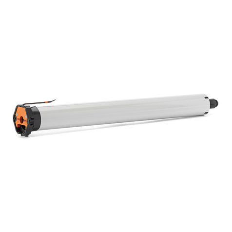
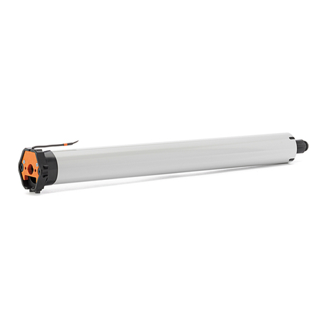
  9. elero VariEco M DC User manual

elero VariEco M DC User manual

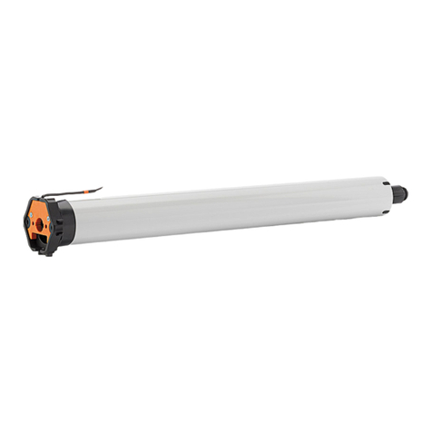
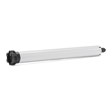
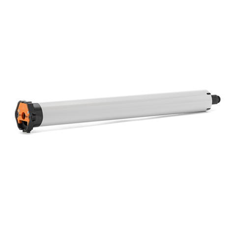
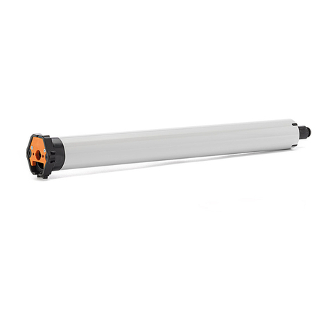
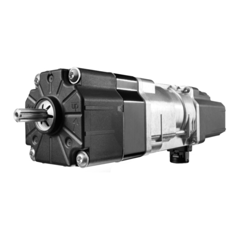
VariEco M DC
Assembly instructions
138170701_EN_0917
General
Application: Drive for roller shutters and textile sun protec-
tion
Power supply: Direct current (DC) 12 V (e.g. elero energy
unit)
Limit switch: Mechanical limit switches
Special feature: Noiseless soft brake
Shaft size: From Ø 50 mm
Standard scope of delivery
• 3 m plug-in connecting cable, assembly instructions
Accessories (not included in the scope of delivery)
• Adapter sets, motor bearing, couplings, setting tool, ener-
gy unit
Safety instructions
General safety instructions for use including installation of
drives for roller shutters, awnings, textile sun protection and
venetian blinds can be found in the "Safety instructions" leaf-
let supplied with each drive. Please read the general safety
instructions and this installation manual carefully as the pro-
cedure in this manual is a prerequisite for correct use of the
product. Any intervention by unqualied personnel or failure to
comply with warnings may lead to personal injuries or materi-
al damage.
Figures included are for illustration purposes only. The illus-
trations may di󰀨er from your product with respect to minor
details and are provided for general information only.
elero GmbH continuously strives to improve all products. As a
result, the specications, features and technology of this pro-
duct may be changed at any time. The information provided is
based on current information at the time of publication.
No claims can be derived from the technical data, images and
information provided in this manual.
&$87,21
Installation in prole
tubes
Installation in round tubes
1
4
2
3
Assembly
• Only connect the drive with the power turned o󰀨.
• The limit switch only functions if the drive has been installed
properly in the winding shaft.
• Never adjust the end position to a mechanical stop.
• The length of the winding shaft is to be determined for each
individual installation depending on the drive head and motor
bearing used at the installation site.
Installation in prole tubes (see Figure)
• Push the drive with relevant adapter and limit switch crown
into the prole tube.
• Secure the drive in the motor bearing.
• Secure the counterpart support to prevent axial movement
(screw on the idler or rivet it on).
• Attach the blind to the winding shaft.
Do not drill holes in the area of the drive.
Installation in round tubes (see Figure)
• On the round tube, cut a slot in the end of the tube on the
drive side (width 4 mm, length 16 mm).
• Push the drive into the round tube so that the drive lug of
the limit switch crown engages in the slot.
• Screw or rivet the adapter onto the winding shaft.
• Secure the counterpart support to prevent axial movement
(screw on the idler or rivet it on).
• Attach the blind to the winding shaft.
Do not drill holes in the area of the drive.
M
red
brown
white
black
energy unit
12 V DC
Setting tool for adjustment of the end positions
NOTE: For activation of the limit switch setting screws, use
the setting tool or a 4 mm hexagon socket tool. Never use an
electric screwdriver!
Connection example
Pin assignment for the power supply or for interlo-
cked venetian blind push button or switch
Function Wire colour
UP ▲ or DOWN/CLOSE ▼ brown
+ 12 V (positive terminal) white
DOWN/CLOSE ▼ or UP ▲ red
- 0 V (negative terminal) black
NOTE:
The motor controls in UP/DOWN direction must be interlocked
with one another.
A reversing delay of at least 0.5 seconds must be ensured.
Take account of voltage drops with longer line lengths.
CAUTION
DC motor
junction box
momentary
contact switch /
switch
red UP
brown DOWN
white + 12 V
black - 0 V
Technical data and dimensions
The technical data specified is subject to tolerance factors
(according to applicable standards).
Size / Type VariEco M10
DC
VariEco M12
DC
Rated voltage [V] 12 (DC) 12 (DC)
Noiseless soft brake  
Rated torque [Nm] 10 12
Rated speed [rpm] 16 16
Rated current [A] 4.0 3.5
Rated power consumption [W] 48 42
Shaft diameter [mm] 50 50
Protection class (IP) 44 44
Limit switch range (revolutions) 35 35
Operating time (min S2) 10 10
Length C [mm] 477 497
Length D [mm] 460 480
Length E [mm] 14 14
Weight [kg] 1.6 1.7
Ambient operating temperature [
°C
] -20 ... 60 -20 ... 60
Conformity
Protection class II  
Plug-in connecting cable [m] 3.0 3.0
Item number 34 621.0101 34 611.0101
EU Conformity
elero hereby declares that this device is in compliance with all
applicable regulations of the Machinery Directive 2006/42/EC.
The full text of the EU Declaration of Conformity is available
at the following Internet address: www.elero.de/downloads-
service/
Notes on troubleshooting
Fault Cause Remedy
• The drive does
not switch o󰀨
in the end posi-
tions via the limit
switches
• The limit
switch crown
is not being
driven
• Readjust instal-
lation and limit
switches via the
limit switch setting
screws
• Drive does not
react
• Temperature
limiter has
triggered
• Incorrect con-
nection
• Allow drive to cool
down. Tempera-
ture limiter is self-
resetting.
• Readjust connec-
tion
Manufacturer's
address
Service
elero GmbH
73278 Schlierbach
GERMANY
www.elero.de
If malfunctions have occurred or the
device has been damaged despite
proper handling, contact your contrac-
tor or dealer.
Adjustment of end positions
Important: The limit switch setting screws for the upper end
position and lower end position are assigned depending on
the parallelism of the rotating limit switch crown with the run-
ning direction arrow (see Figure).
The basic factory setting when delivered is centrally set at 5
revolutions.
6 revolutions of one of the two limit switch setting screws
corresponds to 1 revolution of the winding shaft.
Turning the limit switch setting screw from negative to positive
causes the travel path of the blind to increase.
Upper end position
1. Let the drive (with no connection to the blind) run in the
DOWN/CLOSE direction until it switches o󰀨 automatically.
2. Attach the rolled-down blind to the shaft.
3. Push the UP button and keep this held down.
4. If the drive switches o󰀨 before it reaches the desired end
position, turn the limit switch setting screw towards positive
until the desired blind position has been reached.
5. If the drive does not switch o󰀨 automatically when the desi-
red end position has been reached, release the button. Run
the blind slightly in the other direction. Turn the correspon-
ding setting screw towards negative and approach the end
position again. Repeat this process until the desired end
position has been reached.
Lower end position
1. Push the DOWN/CLOSED button and keep this held down.
2. If the drive switches o󰀨 before it reaches the desired end
position, turn the limit switch setting screw towards positive
until the desired blind position has been reached.
3. If the drive does not switch o󰀨 automatically when the desi-
red end position has been reached, release the button. Run
the blind slightly in the other direction. Turn the correspon-
ding setting screw towards negative and approach the end
position again. Repeat this process until the desired end
position has been reached.
Checking the end positions
Allow the drive to run alternately in both directions until the
limit switch switches o󰀨. The electric cut-out must take place
before the blind has reached the end position of its mechani-
cal travel path.
If the blind is constantly operated as far as its end position,
there is a risk that the drive and/or blind will be damaged or
destroyed.
NOTE: The limit switch only functions if the drive has been in-
stalled properly in a winding shaft (prole tube or round tube).
Limit switch set-
ting screws
Setting tool
Limit switch crown with
drive lug
• Negative sense of rota-
tion (-) = shorter travel
• Positive sense of rotati-
on (+) = longer travel
Direction of travel arrows
33
D
C
14E=
Stator FE C D
Motorrohr
Rol/Sun
381 364 339
391 374 349
456 439 414
466 449 424
486 469 444
526 509 484
546 529 504
RolTop M1,8/138 RH Neher 384493401 120 556 539 514
RolTop M1,8/138-868 RH Nehe r 384403406 120
Baugröße Typ
55
C
D
14E=
12E=
45O
55O52,7
C
D
33
33
C
D
33
12E=
45O
45O45O
O52,7
C
D
33
45O
O57,5
19E=
C
D
33
45O
O57,5
19E=
33
D
C
14E=
Stator FE C D
Motorrohr
Rol/Sun
381 364 339
391 374 349
456 439 414
466 449 424
486 469 444
526 509 484
546 529 504
RolTop M1,8/138 RH Neher 384493401 120 556 539 514
RolTop M1,8/138-868 RH Nehe r 384403406 120
Baugröße Typ
55
C
D
14E=
12E=
45O
55O52,7
C
D
33
33
C
D
33
12E=
45O45O45O
O52,7
C
D
33
45O
O57,5
19E=
C
D
33
45O
O57,5
19E=
±


±
Other elero DC Drive manuals

elero RolMotion M-868 Product guide

elero

elero RolMotion M-868 Product guide

elero CSM-868 User manual

elero

elero CSM-868 User manual

elero RolMotion/D+ M Series Product guide

elero

elero RolMotion/D+ M Series Product guide

elero JA Comfort  series User manual

elero

elero JA Comfort series User manual

elero LIMAline 60 User manual

elero

elero LIMAline 60 User manual

elero DFM 100 User manual

elero

elero DFM 100 User manual

elero RolMotion/D+ M-868 Product guide

elero

elero RolMotion/D+ M-868 Product guide

elero RolTop-868 User manual

elero

elero RolTop-868 User manual

elero KL/DMA User instructions

elero

elero KL/DMA User instructions

elero SunTop-868 User manual

elero

elero SunTop-868 User manual

elero RolTop S Specification sheet

elero

elero RolTop S Specification sheet

elero SunTop/Z M-868 User manual

elero

elero SunTop/Z M-868 User manual

elero VariEco L RH Product guide

elero

elero VariEco L RH Product guide

elero SunTop Product guide

elero

elero SunTop Product guide

elero SunTop-915 User manual

elero

elero SunTop-915 User manual

elero RolTop Series User manual

elero

elero RolTop Series User manual

elero VariEasy M10 SH Product guide

elero

elero VariEasy M10 SH Product guide

elero JA comfort SMI series User manual

elero

elero JA comfort SMI series User manual

elero AeroTec 28 140.0001 User manual

elero

elero AeroTec 28 140.0001 User manual

elero SunTop/Z M RH User manual

elero

elero SunTop/Z M RH User manual

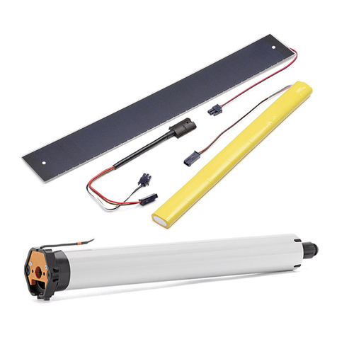
elero Solar-Bundle DC User manual

elero

elero Solar-Bundle DC User manual

elero RolMotion M Product guide

elero

elero RolMotion M Product guide

elero RolTop D+ 868/915 User manual

elero

elero RolTop D+ 868/915 User manual

elero CSM-F-868 User manual

elero

elero CSM-F-868 User manual

Popular DC Drive manuals by other brands

Delta VFD-A user manual

Delta

Delta VFD-A user manual

Delta VFD-EL-C Series user manual

Delta

Delta VFD-EL-C Series user manual

Iron Horse GSD7 Series user manual

Iron Horse

Iron Horse GSD7 Series user manual

Delta Compact Drive MS300 IP66/NEMA 4X Series user manual

Delta

Delta Compact Drive MS300 IP66/NEMA 4X Series user manual

KEBCO COMBIVERT F5 Series instruction manual

KEBCO

KEBCO COMBIVERT F5 Series instruction manual

Oriental motor AlphaStep AZ Series user manual

Oriental motor

Oriental motor AlphaStep AZ Series user manual

System air FRQ5S-E-10A operating instructions

System air

System air FRQ5S-E-10A operating instructions

ATO EM15-SP Series user manual

ATO

ATO EM15-SP Series user manual

GM International D5048S Instruction & safety manual

GM International

GM International D5048S Instruction & safety manual

Lenze 9300 vector Series Mounting instructions

Lenze

Lenze 9300 vector Series Mounting instructions

Magnetek Elevator HPV1000 AC Guide

Magnetek Elevator

Magnetek Elevator HPV1000 AC Guide

BeiJer BFI-P2 Series Installation & user guide

BeiJer

BeiJer BFI-P2 Series Installation & user guide

Aerotech Automation1 iXC4 Hardware manual

Aerotech

Aerotech Automation1 iXC4 Hardware manual

Rockwell Automation Allen-Bradly 1397 user manual

Rockwell Automation

Rockwell Automation Allen-Bradly 1397 user manual

Danfoss VLT FC 300 instruction manual

Danfoss

Danfoss VLT FC 300 instruction manual

Minarik BOSS Series user manual

Minarik

Minarik BOSS Series user manual

Siemens SKB62 Series Mounting instructions

Siemens

Siemens SKB62 Series Mounting instructions

DeVilbiss QS-5001 Service bulletin

DeVilbiss

DeVilbiss QS-5001 Service bulletin

manuals.online logo
manuals.online logoBrands
  • About & Mission
  • Contact us
  • Privacy Policy
  • Terms and Conditions

Copyright 2025 Manuals.Online. All Rights Reserved.