Eli Ezer EDC-2600 User manual


2
IMPORTANT NOTICE
•
Intended Use
EDC-2600 is a digital chart that provides necessary chart for visual acuity measurement and
images for additional explainations.
The user can use the remote controller to show the desired chart and contents, and the program
function allows the optometrist to select and display chart when measuring.
It provides a variety of basic charts for visual acuity measurement and aids such as binocular
balance test, horizontal / vertical aniseikonia test, phoria test, and color vision test.
•
Classifications
[Classification under the provision of 93/42/EEC(MDD)] Class I
The EDC-2600 is classified as Class I a device
[Form of protection against electric shock] Class
Ⅰ
The EDC-2600 is classified as Class I.
This product is always protected when you connect the power supply must be connected to ground
included. Class I is a product in which the protection against electric shock does not rely on basic
insulation only, but which includes an additional safety precaution in such a way that means are
provided for the connection of the product to the protective (ground) conductor in the fixed wiring of
the installation in such a way that accessible metal parts cannot become live in the event of a failure
in the basic insulation. Use a power outlet which is equipped with a grounding terminal.
[Degree of protection against ingress of liquids] IPX0
The EDC-2600 is classified as IPX0
[Degree of protection against flammability]
The EDC-2600 is classified as a device not suitable to be used in a potentially
flammable environment. Do not use near flammable materials
[Mode of operation]
Classification of EDC-2600 : continuous operation

•Caution
This product may malfunction due to electromagnetic waves caused by portable personal
telephones, transceivers, radio-controlled toys, etc.
Be sure to avoid having objects such as, which affect this product, brought near the product.
It should be used under the supervision of medical staff of hospital
The information in this publication has been carefully checked and is believed to be entirely
accurate at the time of publication. EDC-2600 assumes no responsibility, however, for possible
errors or omissions, or for any consequences resulting from the No use of the information contained
herein.
EDC-2600 reserves the right to make changes in its products or product specifications at any
time and without prior notice, and is not required to update this documentation to reflect such
changes.
“ Do not modify this equipment without authorization of the manufacturer.”
“ If this equipment is modified, appropriate inspection and testing must be
conducted to ensure continued safe use of equipment”
US Ophthalmic LLC
9990 NW 14 ST STE 105 Doral, FL 33172
All rights reserved.
This manual may not be copied in whole or in part without the prior written consent.

4
MDSS Medical Device Safety
Service Schiffgraben 41
30175 Hannover, Germany
SAFETY INFORMATION
Accessory equipment connected to the analog and digital interfaces must be certificated according
to the respective IEC/EN standards (e.g. IEC/EN 60950 for data processing equipment and IEC/EN
60601-1 for medical equipment).
Furthermore all configurations shall comply with the system standard EN 60601-1-2:2007.
Everybody who connects additional equipment to the signal input part or signal output part
configures a medical system, and is therefore responsible that the system complies with the
requirements of the system standard EN 60601-1-1:2001.
If in doubt, consult the technical service department or your local representative.
For EU Countries
The following mark, the name & address of the EU Representative shows compliance of the
instrument with Directive Council Directive 93/42/EEC of 14 June 1993 as amended by
Directive 2007/47/EC concerning medical devices.
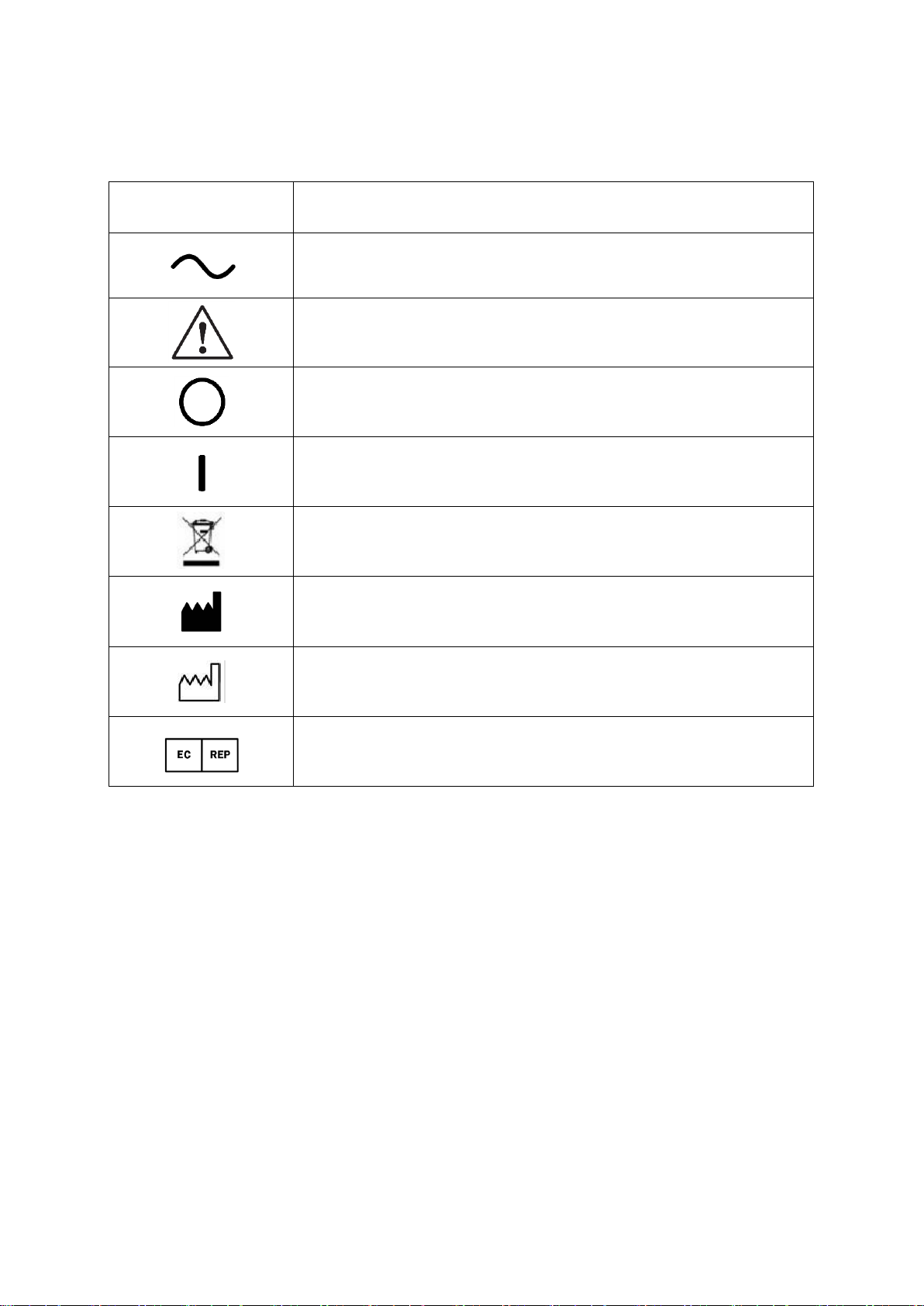
SYMBOLS
Symbol
Description
Alternating current
General warning (find the Annex)
Off
On
DO NOT dispose waste
Manufacturer
Manufacturing date
Authorized Europe representative

6
General Safety Information
Follow the safety instructions on this manual when WARNING or CAUTION appears from the
warning labels under. Ignoring the warning labels during the operation may cause injury or accident.
Be sure to read and understand fully this manual before using the product.
Keep this manual in easy-to-access place.
Warning for safety
!
WARNING
It indicates fatal situations may occur which may result in injury or death.
!
WARNING
It indicates fatal situations may occur which may result in personal injury
or instrument malfunction.
NOTE
It contains significant information about installation, operation, basic
safety and management. Please read to avoid incorrect operation.
!
WARNING
Use this instrument within standard power requirements suggested on
the plaque. Otherwise, fire or electric shock may occur.
!
WARNING
All cables must be connected or disconnected after turn off the power.
DO NOT touch cables with wet hands. This may result in serious injuryor
death due to electric shock.
!
WARNING
Turn off the switch and disconnect the power cable from AC immediately,
and ask for help to the purchased store if followings occur:
In case of smoke, odor, and noise occur
In case of spilling liquid or dropping metal in gap
In case of dropping instrument or breaking case
!
WARNING
DO NOT disassemble or modify the instrument. It may cause fire or
electric shock. In addition, this instrument contains dangerous and high
voltaged parts that may result in serious injury.
!
WARNING
Keep the temperature of 10℃~40℃and humidity of 30%~90%
(In Operation)
!
CAUTION
This instrument equipped grounded power cable. Connect it to grounded
outlet always in order to reduce electric shock.
!
CAUTION
Be cautious dusts or metals go into the instrument.
!
CAUTION
DO NOT hold the cord to pull out the plug.

Table of Contents
IMPORTANT NOTICE
………………………………
3
SAFETY INFORMATION
………………………………
4
GENERAL SAFETY INFORMATION
………………………………
6
1. Features
………………………………
9
2. Introductions for use
………………………………
10
3. Functions of each parts
………………………………
11
4. Installation
………………………………
18
5. Operation
………………………………
20
6. Operation mode
………………………………
21
7. Menu mode
………………………………
22
8. Program mode
………………………………
25
9. Maintenance
………………………………
26
10. Specifications
………………………………
28

8
1.
Features
For convenient and stable test, EDC-2600 guarantees clearer view with 24” FHD
wide monitor and supports high-resolution display.
Installation distance is 1.5m to 7.0m for the adjustment according to user‟s optometry
environment, and can be installed and used at limited place by using mirror feature.
A high-performance Polarizing filter allows Polar test in any installation distance.
Contrast adjustment feature for contrast sensitivity test that eases visual acuity test for all
patients, especially cataract patient, is available.
Black-white reversal feature offers convenient test patients who had Lasik surgery.
For prompt and accurate test, EDC-2600 is usable alone with remote control, and linkable to
use with EDR.
The latest program is available to update easily by using USB flash drive.

Instructions for use
Electromagnetic waves from mobile phones, radiotelegraphs, remote-controlled toys, etc.,
may cause malfunction on this product. Please keep any influential device away from this
EDC-2600.
All information on this manual confirmed thoroughly before publication. However, US
Ophthalmic LLC., has no responsibility on any result from error, omission, or misuse
of the information.
US Ophthalmic LLC., has rights to modify the products or specifications without any prior
notice, as well as not renewing modified information for this manual.
Keep the temperature(10℃~40℃) and humidity(30%~90%) for normal operation.
Avoid excessive shock or vibrate on the EDC-2600.
In case of connecting EDC-2600 with another or moving, please follow the guides of
technician or service agent. Please place it flat floor.
Exterior lighting affects the test. Use the instrument in an appropriate optometry room.
Keep the monitor clean to avoid incorrect measurement, and check the monitor before use.
Shocks may bring internal or external damage. Handle it with care.
DO NOT expose EDC-2600 to the bright indoor lights or direct sunlight.
Keep inflammables such as alcohol, thinner, and other chemicals away from EDC-2600
Turn off the power when EDC-2600 is unused for long time after the measurement.
Install EDC-2600 on the properly grounded refractor table to reduce electric shock.
Please separate junction box and converter box from external case in case of installation
of EDC-2600 and EDR together on the unsuitable grounded refractortable.

10
③
Wall mountholes
2.
Functions of each part
EDC-2600 is consisted of main body, cradle for wall mount, remote control, and
accessories. Explanations and functions of each component are as followings.
2.1. Main body
The main body of EDC-2600 is the most significant part, and installed on the cradle.
②
State LED
①
Remote control receiver
[Figure 1] Front
[Figure 2] Rear

④
Serial cable port
⑤
Power switch
⑥
USB port
⑦
Adapter connector
[Figure 3] Side I/O

12
Descriptions
Function
①Remote control signal receiver
Receives signal from remote control..
②State LED
Shows power state in LED.
Green: power is on.
③Wall bracket hole
Place bracket on it, and tight the bolts to assemble the cradle
and main body.
④Serial cable port
Connects digital refractor and connected chart cable.
⑤Power switch
A switch for power
It may run in about 8seconds after power on
⑥USB port
Uses to connecting USB flash drive and supports 2 ports.
⑦Adapter connector
Supplies power by connecting the adapter. Before the
connection, separate power cable and outlet.
[ Chart 1 ] Main body

3. Set up button
4. Program button
2. Power button
1. IR Sensor
7. Arrows
5. Slide button
6. Mask button
3.1. Remote control
Turns LCD chart on and off with remote control, and changes display for test.
[ Figure 4 ] Remote control

14
Descriptions
Function
1. IR Sensor
Sends signal from the remote control to the main body.
2. Power button
Turns power on or off
Do
turn
off
main
switch
on
backside
when
don
‟
t
use
unit
for
a
long time
3. Set-up button
Set the menu for user
‟
s convenience.
4. Program button
PROGRAM A/B : Select program A or B
NEXT : Go next page
PREV : Go previous page
5. Slide button
Starts or ends the Slide mode.
6. Mask button
Set vertical / horizontal / single characteristic mask.
7. Arrows
Moves mask or to the next chart
[ Chart 2 ] Remote control

The Apdapter specipication is DC 5V / 5A.
You must use adapter and cable that provided by US OPhthalmic.
The adapter that provided by US OPhthalmic have medical
certification. US OPhthalmic have no responsibility about problem
that caused by using adapter and cable which are not provided by
US OPhthalmic.
Model : GSM40A05
2.2. Accessories
Accessories of EDC-2600 are composed standard products and optional products.
①②③
⑤
⑥⑦
(Optional) (Optional)
[ Figure 5 ] Accessories
Descriptions
Function
Q’ty
①Batteries
1.5V AA size batteries
2
②Adapter
A power supplier to the main body
1
③Power cable
A power supplier to the main body
1
④Serial cable
A cable connects with digital refractor for use.
1
⑤Wall bracket
A bracket fixes the main body on the wall.
1
⑥Polarized glasses (Optional)
Glasses for polarized test
1
○
7 Red/green glasses (Optional)
Glasses for red/green chart test
1
[ Chart 3 ] Accessories
④
! WARNING

16
4.
Installation
3.1 Parts list
ID
Q
‟
ty
Descriptions
1
1
Wall plate
2
1
Adapter bracket
3
2
Safety bolt
A1
4
M4x8mm bolt
4
M4x12mm bolt
A2
4
M5x8mm bolt
4
M5x12mm bolt
A3
4
M5 washer
B1
2
Long bolt
B2
2
Wall anchor
B3
2
Long bolt washer

3.2 Installation guide
Stage 1
A) Wood stud mounting
1) Place wall plate on a wood stud to mark two mounting holes.
2) Use long bolts (B1) and long bolt washers (B3) to tight wall plate on the wood stud.
*<CAUTION> DO NOT tight bolts excessively.
B) Concrete wall mounting
1) Place wall plate on the wall to mark two mounting holes.
2) Drill mounting holes 60mm deep with 10mm drill bit.
3) Insert anchors (B2) on the holes, and tight long bolts (B1) and long bolt washers (B3) tightly.
*<CAUTION> DO NOT tight bolts excessively.

18
Stage 2
1) Align the mounting holes after placing adapter bracket behind the monitor closely.
2) Attach M5 Washer (A3) by tighten bolts (A1-A2)
*<CAUTION> DO NOT tight bolts excessively.
Stage 3
1) Slide the adapter bracket (2) into wall plate (1).
2) Tight safety bolt (3) to fix the monitor.

5.
Operation
Remote control and digital refractor panel operate EDC-2600, but this manual ONLY
contains information about operation with remote control. Please refer to separated manual to
use digital refractor.
Power control feature
Use switch on the bottom of the main body, or remote control to turn on or off EDC-2600.
Do
turn
off
main
switch
on
backside
when
don
‟
t
use
unit
for
a
long
time
Power saving mode
Power saving mode will on when the product is not used.
Time can be set up. (1min, 3mins, 5mins, 10mins)
When any button on the remote control or refractor is pressed, saving power mode will
canceled.
Set up mode
Press [Set-Up] on the remote control to enter set up mode. Detailed information is on
Chapter 7 “Set up.”
Slide mode
Press [Slide] on the remote control to enter slide mode. Detailed information is on Chapter 3
and 6 “Slide mode.”
Visual acuity chart
Visual acuity charts are composed three categories with standard chart (Landolt ring,
Snellen), character chart #1 (Number/English character), and character chart #2
(Number/English character/ Korean character).
Press CHART SELECTION to change chart.
Press CHART SELECTION repetitively to see random chart.
Press MASK to show only chart with single character, horizontal line or vertical line.
Press RED/GREEN FILTER to see red/green chart.
Press CONTRAST to adjust contrast. The value will increase as the button is pressed.
Press WHITE/BLACK to see reversed black and white image.

20
Additional chart
Chart
Function
Invert colors of character and background at character
chart
Test contrast sensitivity at character chart.
Astigmatoscopy chart
Detailed astigmatoscopy chart with cross cylinder
lens.
Balance test chart
Binocular balance test chart
Red/green background at character chart
Worth 4 Dot chart
Shober chart
ETDRS chart
Dyslexia chart
Prescribed prismatic chart to correct strabismus
Red LED with Maddox rod
Aniseikonia test chart
Prescribed prismatic Cross chart to correct
strabismus.
Table of contents
Other Eli Ezer Medical Equipment manuals
Popular Medical Equipment manuals by other brands

Physio Logic
Physio Logic DigiPulse user guide

Hillrom
Hillrom Welch Allyn FlexiPort Blood Pressure Cuffs Instructions for use

ARJO HUNTLEIGH
ARJO HUNTLEIGH Bari-Breeze user manual

ARJO HUNTLEIGH
ARJO HUNTLEIGH maxi sky 440 Instructions for use

Smartoptics
Smartoptics Activity 850 operating manual

OFFCARR
OFFCARR ALHENA instruction manual