Eli Ezer EPR-2600 User manual


2
Preface
Dear Users:
Thank you very much for choosing EPR-2600 automatic computer perimeter manufactured by us.
For your security and benefit, please read the <Operation Instruction> as well as all the datum
of the instrument carefully before using it.
If you do not operate the instrument according to the Operation Instruction, we shall not take any
responsibility.
About <Operation Instruction> of this Instrument
The copyright of the operation instruction belongs to us;
The content of the operation instruction is written according to the physical goods;
If you can not understand some of the content or clause, or if you meet technical problems when using
it, please do not hesitate to contact us,
We have the right of interpreting and revising this operation instruction.

3
Content
Chapter 1 Summarize………………………………………………………… 4
Chapter 2 Technical parameter ………………………………………………… 7
Chapter 3 Installation …………………………………………………………12
Chapter 4 Software Function……………………………………………………25
Chapter 5 Mantainance…………………………………………………………47
Chapter 6 Declaration………………………………………………………… 48

4
Chapter 1 Summarize
1. Brief Introduction
Projection perimeter,adopt the advantage of international advanced model, projection working
mode,with wide testing range 0-90°.It has the characteristics of full-function, high precision and
speed. Besides the above characteristics, the whole system also has the characteristic of high
dependability and steady performance. Software support Windows XP,WIN7 and Win 8 system
with easy operation interface. Kinds test program and strategy,standard test report and analysis
software, Provide auxiliary diagnosis for vision damage related diseases
2. Notice for use
2.1 For your security and benefit, please read the <Operation Instruction> as well as all the
datum of the instrument carefully before using it.If you do not operate the instrument according to the
Operation Instruction, we shall not take any responsibility.
2.2 Use it in a darkroom and it can only be operated by those who have been trained by
engineers of us.
2.3 The stimulus and PC system can be used in patient environment, printer should be used
outside of patient environment.
2.4 The voltage must be up to the given standard. If the voltage is not steady, please install a
Constant Voltage Regulator. We will not take responsibility for the damage caused by the voltage.
2.5 Do not use this instrument in the inflammable, hot and dusty environment and pay attention
to keep it clean and dry; To avoid being damaged by the environment (Damp, Dusty, Liquid, under
the sun and so on).
2.6 Do not let the liquid or any other small objects run into the instrument, otherwise these
objects may make the inner parts of the instrument short-circuit, and even make the users get an
electric shock or even cause a fire hazard.
2.7 Without the permission of us, do not open the box of the instrument or we will not take the
consequences
2.8 If you need restart the instrument,you can open the perimeter after 5 seconds and open the

5
computer after 15 seconds after turning off.
2.9 Environmental protection clause:It will pollute the environment if you discard the
equipment and the accessories which is breakdown, recall or disposal according to the local laws and
regulations.
2.10 Rated operating loaded and safe working load of chin rest is 5kgs.
About the instruction:
1. If it breaks down, please read the guide to fix the breakdown. If it does not work yet, please
contact us.
2. We have the right of interpreting and revising this operation instruction.
3. Structure components
a)Hardware: It’s mainly structure by computer system, perimeter stimulus, printer, and socket
b)Software: The patient information input module, Image processing modules, Document
management modules,output & print module:
4. Applicability
This instrument is used for examining the change of visual field which may be hurt by glaucoma,
visual disease, disease of brain surgery and disease of retina.
5. Notes
To avoid being damaged by the environment (Damp, Dusty, Liquid, under the sun and so on), the
instrument should be putted at the dry place.
Do not let the liquid or any other small objects run into the instrument, otherwise these objects may
make the inner parts of the instrument short-circuit, and even make the users get an electric shock or
even cause a fire hazard.
6. Manual
Effective for model:EPR-2600
7. Product features
Fusing parts: T2AL 250V

6
Security type:It belongs to B type instrument
The instrument is intermittent working form
Symbolic interpretation:
Notes!Look through the manual
Power on
Power off
Earth wire
B type instrument
Alternating current
Connected(Responder)
Disconnected(Responder)
USB Port
7
Chapter 2 Technical Parameter
2.1 Technical Index
2.1.1 Background light
Background light:white,intensity 10 cd/m2。
2.1.2 Stimulus testing, the allowance under limitation listed in Table 1.
Table 1: Stimulus Parameter
S/N
Content
Allowance
1
Background light,
+25%,-20%
2
Contrast,
+25%,-20%
3
Stimulus location
0°~10°:≤0.5°
10°~30°:≤1°
>30°:≤2°
4
Stimulus size
Conversion to solid angle:+20%,-15%
5
Stimulus duration
±20%
Table 2 Stimulus Size Paramter
Azimuth θ
eccentric angle Φ
b/a
solid angle Ω
0°
15°
>0.7
6.66E-05
40°
>0.6
1.00E-04
45°
15°
>0.7
8.00E-05
40°
>0.5
1.29E-04
90°
2°
Ⅲ
>0.8
6.50E-05
15°
>0.7
8.44E-05
40°
>0.6
1.10E-04
135°
15°
>0.7
6.66E-05
40°
>0.6
1.15E-04
180°
15°
>0.7
6.22E-05
40°
>0.6
9.00E-05
225°
15°
>0.7
6.50E-05
40°
>0.6
7.99E-05
270°
15°
>0.7
6.30E-05

8
40°
>0.6
7.20E-05
315°
15°
>0.7
6.50E-05
40°
>0.6
9.20E-05
Table 3-1 Stimulus contrast ratio(White stimulus-White background)
dB
Stimulus Intensity
Bs LL
Luminance
s
L
Contrast
0
3421.0
3431.0
342.10
1
2898.5
2908.5
289.85
2
2160.5
2170.5
216.05
3
1653.7
1663.7
165.37
4
1367.2
1377.2
136.72
5
1075.2
1085.2
107.52
6
854.73
864.73
85.47
7
674.10
684.10
67.41
8
547.33
557.33
54.73
9
426.74
436.74
42.67
10
333.40
343.40
33.34
11
270.32
280.32
27.03
12
234.00
244.00
23.40
13
200.65
210.65
20.06
14
159.60
169.60
15.96
15
110.21
120.21
11.02
16
90.47
100.47
9.05
17
63.50
73.50
6.35
18
50.24
60.24
5.02
19
40.82
50.82
4.08
20
31.85
41.85
3.18
21
25.69
35.69
2.57
22
20.26
30.26
2.03
23
16.59
26.59
1.66
24
12.70
22.70
1.27
25
10.05
20.05
1.00
26
8.10
18.00
0.81
27
6.86
16.86
0.69
28
5.06
15.06
0.51
29
4.10
14.00
0.41
30
3.19
13.19
0.32
31
2.57
12.57
0.26
9
32
2.00
12.00
0.20
33
1.60
11.60
0.16
34
1.27
11.27
0.13
35
1.00
11.00
0.10
36
0.80
10.80
0.08
37
0.64
10.64
0.06
38
0.50
10.50
0.05
39
0.40
10.40
0.04
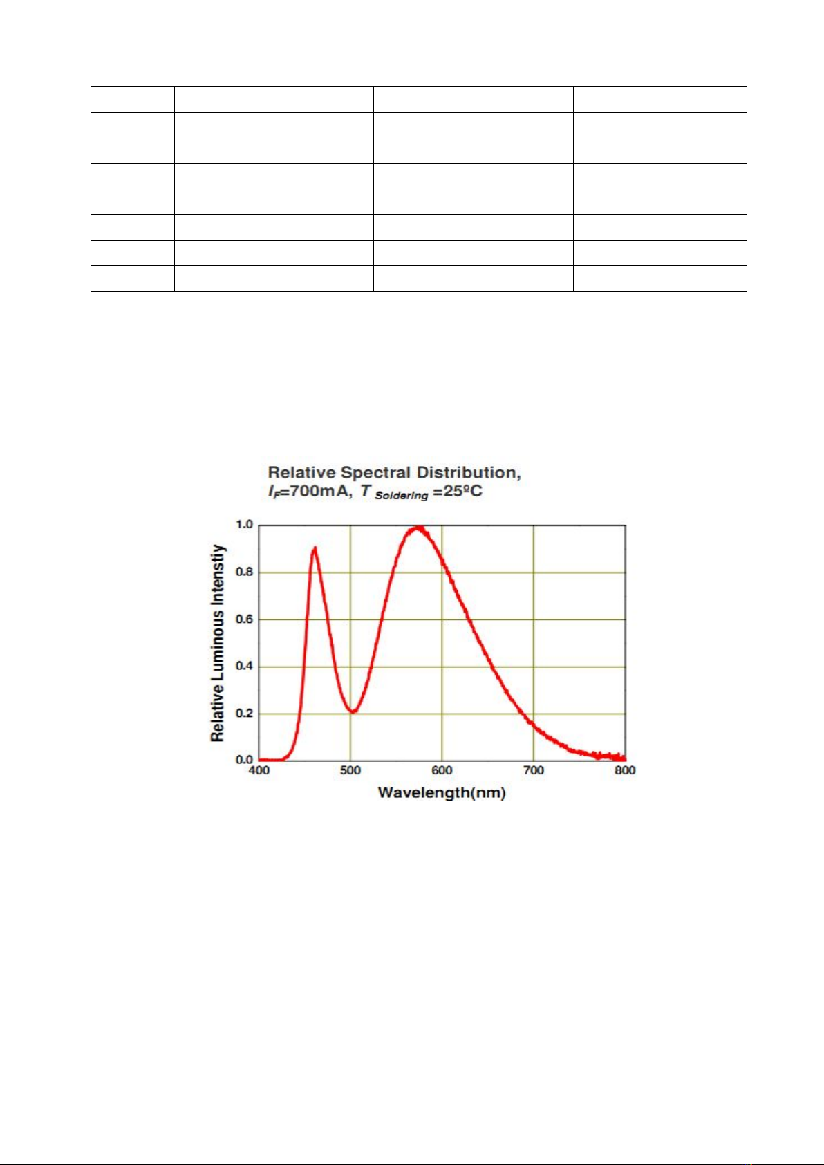
2.1.3 Spectral distribution of Background light and stimulus (white)
2.1.3.1 White background spectrum, white stimulus spectrum
White background spectrum, white stimulus spectrum

10
2.1.4 Stimulus range: full field 90°,testing stimulus minus eccentric angle conform to the requirement
in table 4.
Table 4
Content
minus eccentric angle ф
Nasal
45°
Bitamporal
70°
Upper
45°
Under
60°
While testing,Nasal testing should be proceeded under Nasal step screening test mode.
Botamporal testing should be proceeded under FF135 Screening test mode. Upper and Under should
be proceeded under 60-4 threshold test mode.
2.1.5 Stimulus location amount and stimulation time:
a) Stimulus location amount: cannot less than the requirement listed in table 5
Table 5
Eccentric angle ф
Minimum amount
0°~25°
60
>25°~50°
30
>50°~70°
15
Sum
105
b) Stimulus time of duration:
Kinetic:Movement speed:1°/sec-9°/sec adjustable
Move mode:Straight line
Sample:
Static:Stimulus time of duration 200ms
Stimulus interval:
11
1).If no response from patient, stimulus interval default as 1000ms;
2).If patient response,the system will adjust the stimulus interval according to the weighted
average of last 5 patient respond speed,if patient respond slow then the stimulus interval will be
automatically prolong. If patient respond fast then the stimulus interval will shorten automatically
2.1.6 The distance between patient eye and the fixation:300 mm±10 mm。
2.1.7 The instrument have head location device, and configure movable chinrest and forehead rest,
their travel distance from left-right ≥30 mm,and the chin rest of chinrest from up-down ≥50
mm.
2.1.8 This equipment configure auto calibration function for stimulus intensity, device will calibrate
the background intensity and stimulus intensity automatically while operator power on the equipment.
2.1.9 Input power:300VA。
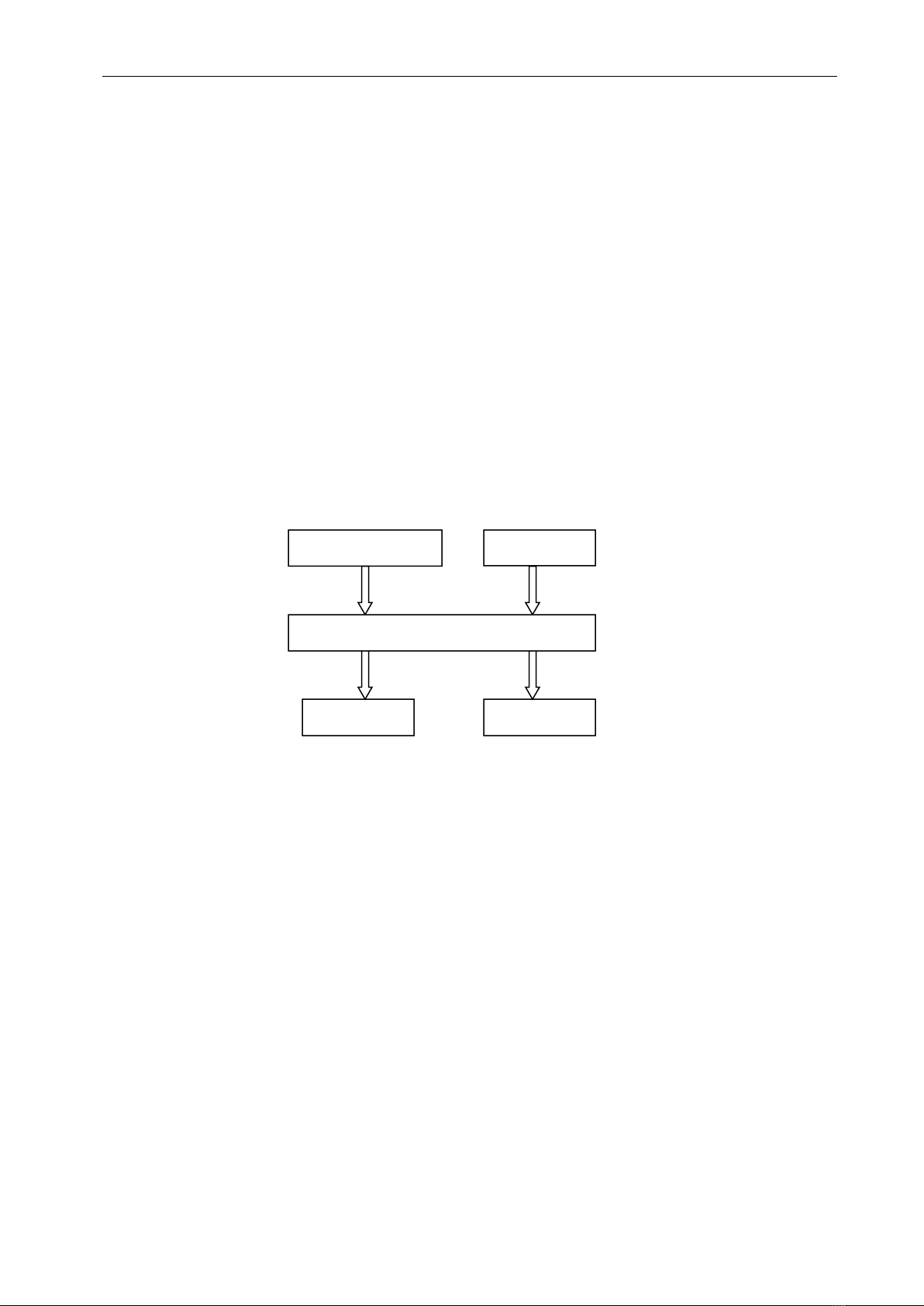
2.2 Flowchart
2.3 Working principle
The working principle of the perimeter is to examining the sensitivity of the human eye to light
stimulus which enable to check the lesions of optic nerve, retina, visual pathway etc. The ambient
light enter into retina by refraction system, then the retinal generate the photochemical reactions
which produce the bioelectrical which transmitted through the visual pathway to visual cortex, so that
the brain could generate the vision through a comprehensive analysis. Any part of the distribution and
the trend of the nerve fibers from the retina to the visual cortex could indicate the lesions which
happened on the visual pathway. The lesion part, the characteristic and prognosis can be all analyzed
by applying the clinic test results according to its visual transform.
Stimulator
Responder
Computer
Display
Print
12
Chapter 3 Installation
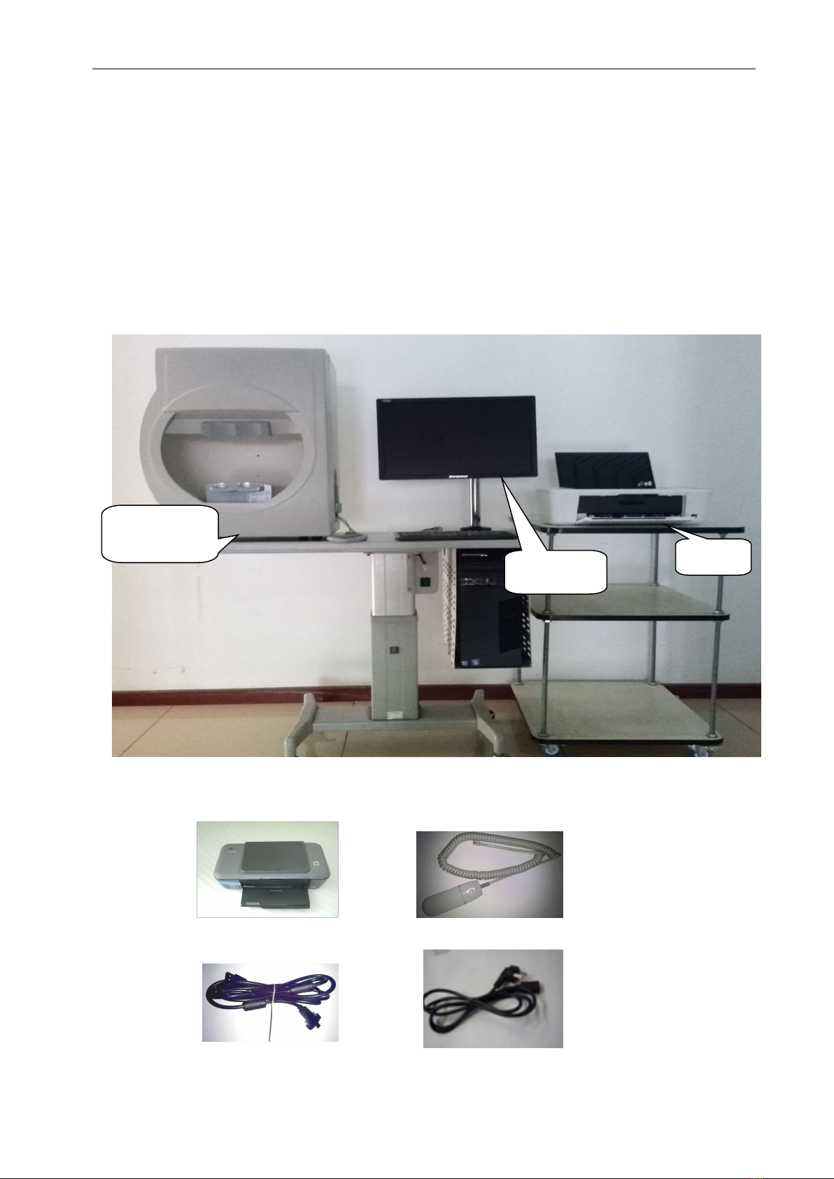
1. Hardware
EPR-2600 projection perimeter have already been inspected and tested before leaving factory.
Please check if all accessories listed on list provided or not,any question, please contact with seller
immediately.
Please check accessories on list.
Picture of Whole instrument
▲Main Spare-Parts
Printer
Responder
Stick
USB Wire
Power wire
Stimulator
Printer
Computer
13
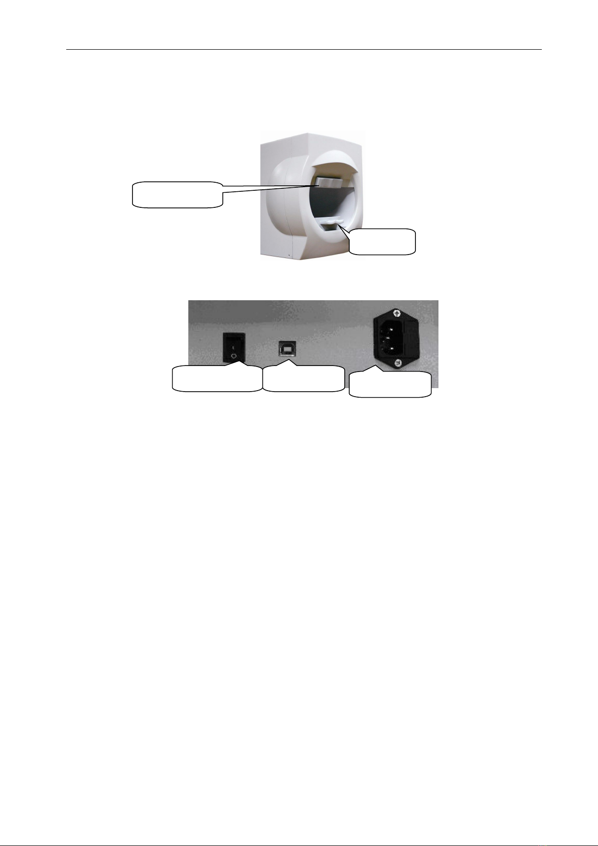
▲ The Front Picture of the Stimulator
▲ The Back Picture of the Stimulator
2. Working Environment
Environment temperature:5℃-40℃
Relative humidity:≤85%
Atmospheric pressure range:760 hPa~1060 hPa
Power:a.c.100~240V;Frequency:50Hz
Inputting power:300VA
3. Installation environment
3.1 The instrument must be installed in the flat ground with no slope;
3.2 The instrument must be installed in the clean, quiet and dry room;
3.3 The instrument must be installed in the dark room where nothing can be seen within one
meter.
3.4 The instrument must be installed with special ground wire;
3.5 The instrument require the exclusive ground wire.
Forehead Rest
Chin Rest
Power On/Off
USB Port
Power Supply
14
4.Hardware setup
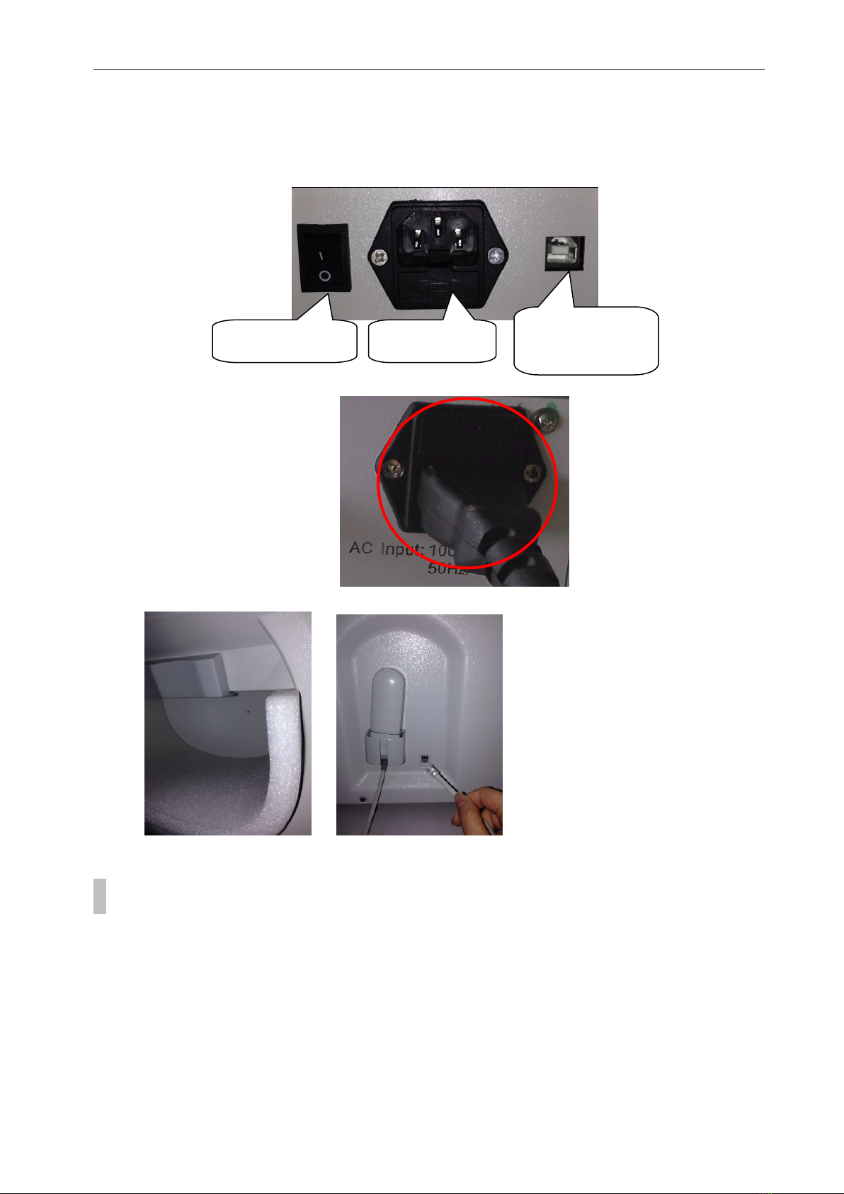
4.1 Connect Perimeter and Computer with the new USB Serial Port Wires we provide.
4.2 Connect the Power of the Perimeter.
4.3 Take out the fixed foam inside the Perimeter. Fix the Responder into the connector.
4.4 Connect the USB cable to computer, and install computer and printer accordingly.
5.Software setup
5.1 Windows System Requirements
English/ Simplified Chinese Version Window XP 32 bit Professional
English/ Simplified Chinese Version Windows 7 32bit/ 64bit Professional
English/ Simplified Chinese Version Windows 7 32bit/ 64bit Ultimate
or English/ Simplified Chinese Version Windows 8 32bit/64bit Professional
PS: We perimeter software only support English/ Simplified Chinese Version Windows system,
if user running others language Windows system, there will be unreadable code showed during install
Power on/off
Power supply
USB connecting
port

15
procedure and on software, or other unpredictable error will be occur. Please use relevant system we
recommended.
Please note the software will be default installed in folder C automatically.
5.2 Hardware Requirements
Before you install PERIMETER V-2.0, make sure your computer meets the following minimum
requirements:
*CPU
Mainboard: Intel chipset
Processor:≥1.7Ghz
multicore:Dual core,4 threaded.
* Memory minimum:≥2GB
* Hard disk
Rotational Speed:≥7200 RPM (Solid-state drives without this parameter)
Caching:≥2MB
Space:≥500GB
*Display
Supporting 1440 * 900 resolution or greater,1440 * 900 recommended.
Perimeter software show normally on resolution of:1440*900,1600*900,1920*1080.
* USB 2.0 Port
▲Make sure there are at least 2 partition “C:” and “D:” existing in the hard disk,
Otherwise the software will run error. Software will go wrong;
▲Make sure there is at least 5GB free space for data storage in partition “D”, otherwise the
software will go wrong.
5.3 After you install the computer system software, Insert install disk we provided into CD-ROM and
copy all the files we provide to your computer’s “D” partition, After the installation, please Do keep
the disc well !
5.4 Software installation procedure
5.4.1 Install USB capture card driver for computer
A:If you run Win XP system,please install the capture card driver as followed steps:
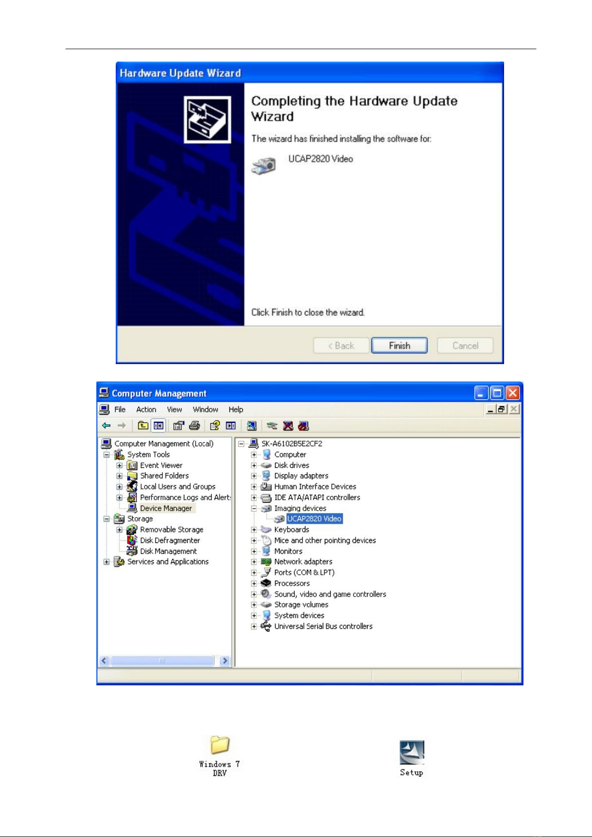
(1) Right click at [My computer],select [Manage] and enter in [Computer Management]

16
(2) Click at [Computer Management], And select [Imaging devices] in the right window.
(3) Right click at [USB Driver] and Click at“Update Driver”as followed pic.

17
(4) A window will pop-up, select [Yes this time only],and continue by clicking [Next].
(5) A window [Hardware Update Wizard] will pop-up, select {Install the software automatically
[Recommended]},then click [Next]

18
(6) A window pop-up like bellow, select [Continue Anyway]
(7) Click [Finish] to end the installation
19
(8) Image shows like below means the driver installed successfully.
B: If you run Win7 system, please install the capture card driver as followed steps:
(1) Open the profile [Driver]
(2) Double click at profile to open it and double click at to start installation
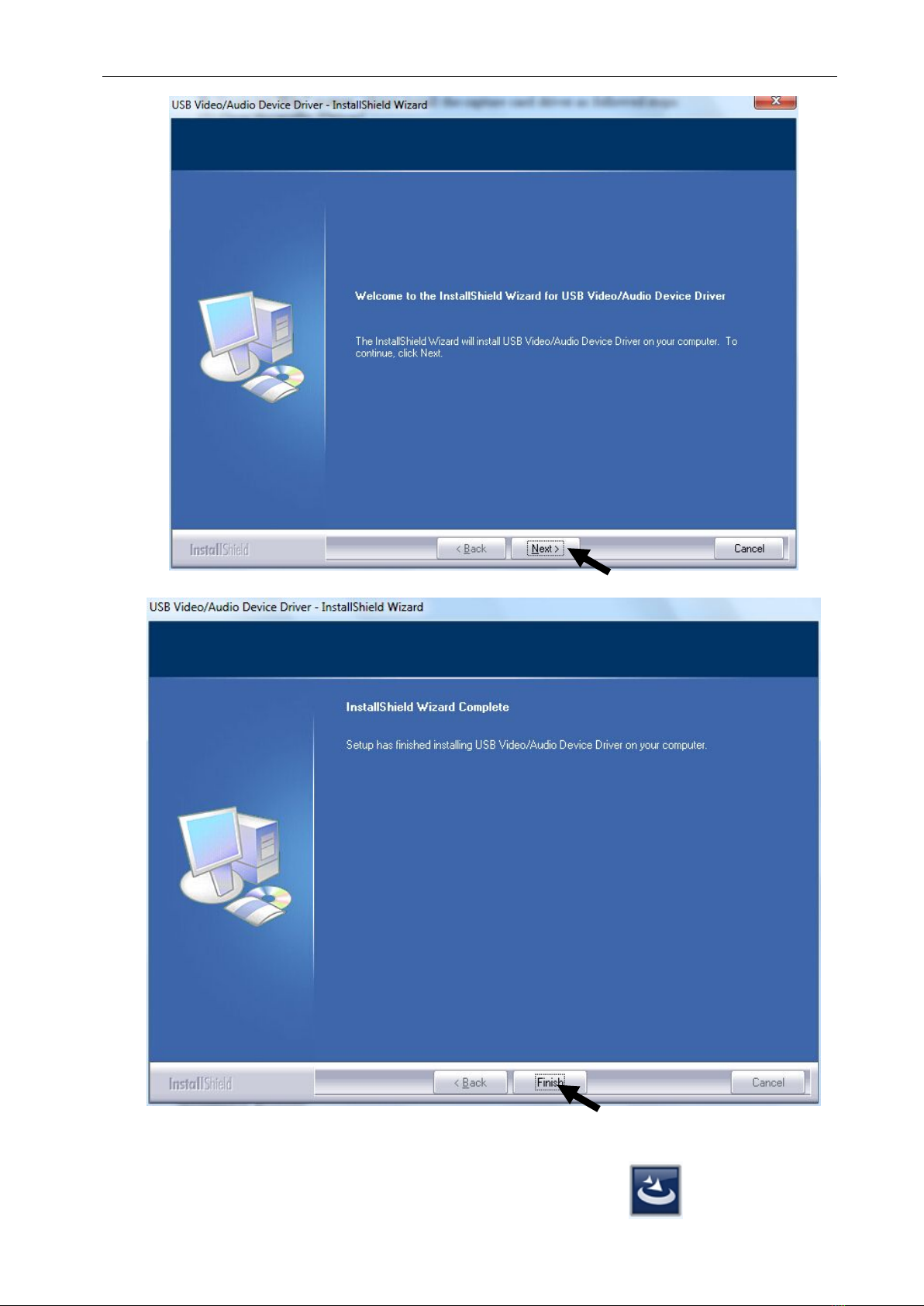
20
(3) Click [Next] to continue,
(4).Click [Finish] icon, restart the computer.
5.4.2 Open the file of perimeter software and double click on icon to start the
Table of contents
Other Eli Ezer Medical Equipment manuals


Popular Medical Equipment manuals by other brands


Getinge
Getinge Arjohuntleigh Nimbus 3 Professional Instructions for use

Mettler Electronics
Mettler Electronics Sonicator 730 Maintenance manual

Pressalit Care
Pressalit Care R1100 Mounting instruction

Denas MS
Denas MS DENAS-T operating manual

bort medical
bort medical ActiveColor quick guide

AccuVein
AccuVein AV400 user manual


