manuals.online logo
Brands
  1. Home
  2. •
  3. Brands
  4. •
  5. Elite
  6. •
  7. Massager
  8. •
  9. Elite Robo-Pad User manual

Elite Robo-Pad User manual

Other manuals for Robo-Pad

1

Other Elite Massager manuals

Elite Robo-Pad User manual

Elite

Elite Robo-Pad User manual

Elite Casada Alphasonic User manual

Elite

Elite Casada Alphasonic User manual

Popular Massager manuals by other brands

Panasonic EP30000 null

Panasonic

Panasonic EP30000 null

ELEEELS P2 instruction manual

ELEEELS

ELEEELS P2 instruction manual

Cenocco CC-9111 user manual

Cenocco

Cenocco CC-9111 user manual

Panasonic EP790-C1 Service manual

Panasonic

Panasonic EP790-C1 Service manual

Adler AD 2167 user manual

Adler

Adler AD 2167 user manual

Taurus Wellness TW-MC-M Assembly and operating instructions

Taurus

Taurus Wellness TW-MC-M Assembly and operating instructions

Infinity Syner-D Circadian Assembly guide

Infinity

Infinity Syner-D Circadian Assembly guide

Hydas LH-095 instruction manual

Hydas

Hydas LH-095 instruction manual

AEG FM 5567 instruction manual

AEG

AEG FM 5567 instruction manual

OBH Nordica Shiatus Tunes manual

OBH Nordica

OBH Nordica Shiatus Tunes manual

Hutech Q9 user manual

Hutech

Hutech Q9 user manual

Medisana MM 825 user manual

Medisana

Medisana MM 825 user manual

SOLAC Therma Hydro Instructions for use

SOLAC

SOLAC Therma Hydro Instructions for use

Invacare Texas user manual

Invacare

Invacare Texas user manual

Casada Bismarck II manual

Casada

Casada Bismarck II manual

Fujiiryoki Cyber-Relax EC-1700 user manual

Fujiiryoki

Fujiiryoki Cyber-Relax EC-1700 user manual

Medisana HM 886 instruction manual

Medisana

Medisana HM 886 instruction manual

HoMedics BA-C200 instruction manual

HoMedics

HoMedics BA-C200 instruction manual

manuals.online logo
manuals.online logoBrands
  • About & Mission
  • Contact us
  • Privacy Policy
  • Terms and Conditions

Copyright 2025 Manuals.Online. All Rights Reserved.

FULL BODY SHIATSU
Assembly Instructions 12
Instruction manual
06
To Begin:
The auto program buttons will begin to flash after the body scanning has completed.
you can now select a manual or auto program.
FuseOn/off
External Electric Plug
Power cord
Instruction manual
08
Buttons On Display:
Description
On Display:
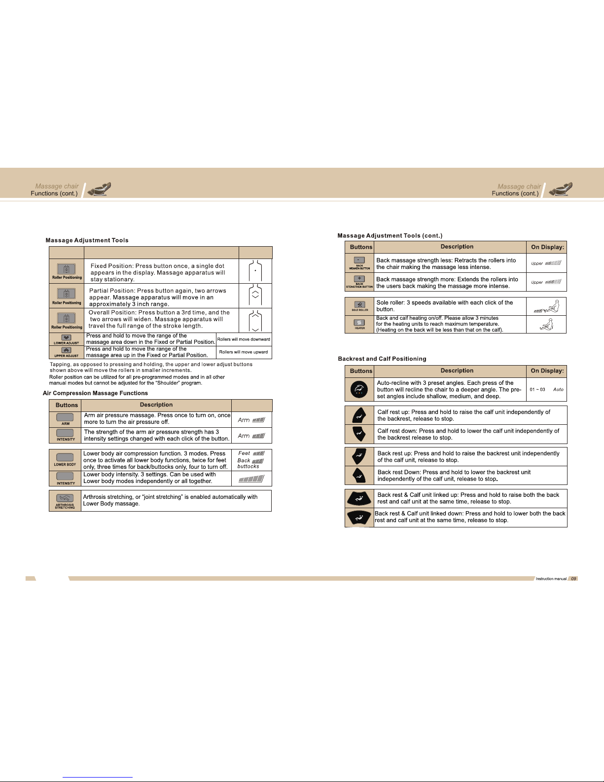
Elite Robo-Pad Assembly Instructions. For questions, clarifications or
assistance call 1-800-592-0548
Your chair arms will be located in a separate box from the chair and require
installation. There are two accessories box located inside the large chair box which
contain the controller stand and upper air bag / speaker assembly'swhich also
require installation.
Tools required: Philips screwdriver, #5 Allen wrench / Hex key (included with chair)
Before you begin assembly, locate and remove the accessories boxes from the large
chair box. Inside the smaller accessories box is the #5 Hex key used to install the
arms in step one. Set the controller stand located in the same box aside to install in
step four. The speaker / upper air bag assembly's are located in the large
accessories box. These will be installed in step three.
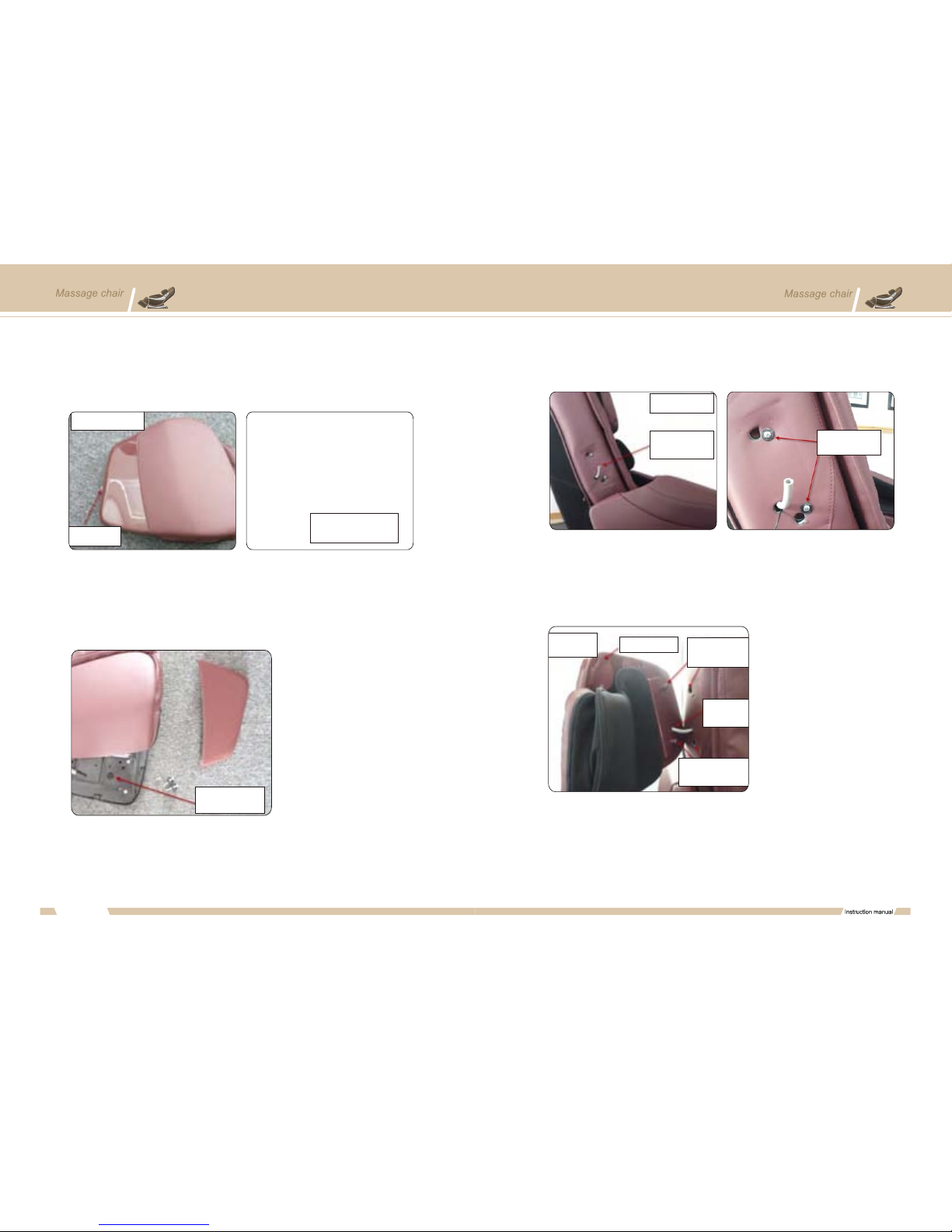
Step 1: Install rightarm.
Step 1A: Connect right armwires and air pipe.Identify whicharm is the right by
the controller stand mount locatedon the exterior of thearm. Identify the correct
side of the chair toinstall the arm. TheRight arm will be whereyour right arm is
located when sitting in thechair
Locate the two wire plugs and air pipe on the right side of the chair. These plugs
should protrude from the square opening shown in the below picture. The wires may
be inside the frame of the chair and you will need to reach through the side of the
chair to pull them out through the square opening.
Locate the correspondingwires on theinterior of thechair arm. Pleasenote
that there isone wire andone air pipefrom the arm.One wire fromthe chair
frame is notused on theright side only. Connect thewhite plug wireand air
pipe
Step 1B: Mount right arm to chair frame.
Note: Before mounting the arm, remove the silver attaching screws which are pre-
screwed into the arm.Locate the white round plastic mounts on the arm, and the
corresponding slots on the chair frame. Place the arm onto the frame at these
locations. The plastic mounts for the arm should slide into their respective locations
on the frame of the chair without applying force; press down slightly on the arm to
lock into place. The chair arm will still fit loosely until mounting screws are re-
attached. Note also the location of the mounting screw holes on the frame of the
chair.
Instruction manual
12
13
Chair
Small accessories
box-controller stand
Large accessories box-
speaker / upper air bag
assembly
Accessories boxes,in
large chair box
Contents of small
accessories box
Controller stand
screws
Hex key used in step
1 to install arms
Controller stand
Controller
stand mount
View of chair - Right
side
Air pipe,2 wires
through square
opening
May need to reach thro-
ugh this opening to locate
wires and air pipe
Air pipe
Two wires
Air pipe and
wire
Back view of arm
Leave this wire
unplugged
Connect wire
and air pipe
Assembly Instructions Assembly Instructions
Step 1C:Install thescrews forthe arm.
Install the screwsremoved in step1B. Thesilver hex keyprovided will be
usedto tighten thescrews
Rear screw location:
Front screw location:
Step 2: Install left arm.
Repeat the procedure for step one. Note that there are two additional plugs for the
left arm, three total, as shown below. Connect the plugs and air pipe accordingly.
The remainder of the procedure is the same as the right arm
Step 3: Installright and leftupper air bag/ speaker assembly.
Step 3A: Removeplastic covering panelfrom speaker assembly.
Locate the speaker/ upper airbag assembly inthe large accessories
box.Note the mountingposts and orientationof the speakerwhich will assist
you to differentiate the leftfrom the rightassembly
Instruction manual
14
15
Arm screw locations,
remove screws
before mounting
Arm
mounts
Back view
of arm
Screw hole
location
Arm mount locations
Screw location
Rear view of chair
Install screw as shown
Screw location
Front view of chair Install screw as shown
Additional plugs
Left arm wires
Chair
Large accessories
box-speaker / air bag
assembly
Accessories boxes,in
large chair box
Speaker / air bag
assembiy front view
Speaker Speaker / Air bag
assembly rear view
Mounting
posts
Assembly Instructions Assembly Instructions
Step 3B: Mount the speaker / air bag assembly
Once the panel is removed, note the location of the wire / air pipe hole in the
assmebly. This will be used to feed through the air pipe and wire from the mounting
locaiton on the chair.
Locate the mounting location for the speaker / air bag assembly on the chair, remove
the screws from this location
Mount the airbag / speakerassembly by insertingthe mounting postsinto the
large holes onthe side ofthe chair.Ensure the speakeris facing upwardsas
shown. Feed theair pipe andwire through thehole in thespeaker / airbag
assembly
Instruction manual
16
Remove the plasticcovering panel fromthe rear ofthe speaker assembly.
Remove the onescrew from theedge of thepanel. You may haveto gently pry
the panel off of theassembly using asmall flat headscrewdriver.
17
Speaker / Air bag
assembly front view
Remove screw Pry apart gently using
screwdriver
Hole for air pipe
and wire
Side view of chair
Speaker / air bag
assembly mounting
location
Remove mounting
screws
View from front
of chair
Speaker Insert mounting
posts into large
holes
Feed air pipe
and wire
through hole
Insert mounting posts
into large holes
Assembly Instructions Assembly Instructions