Eljen GSF A42 User manual

Geotextile Sand Filter
CORPORATION
Innovative Onsite Products & Solutions Since 1970
Indiana
Design & Installation Manual
www.eljen.com
June 2018

2018 Indiana Design and Installation Manual 2 www.eljen.com
Table of Contents
SUBJECT PAGE
GLOSSARY OF TERMS .............................................................................................................................. 4
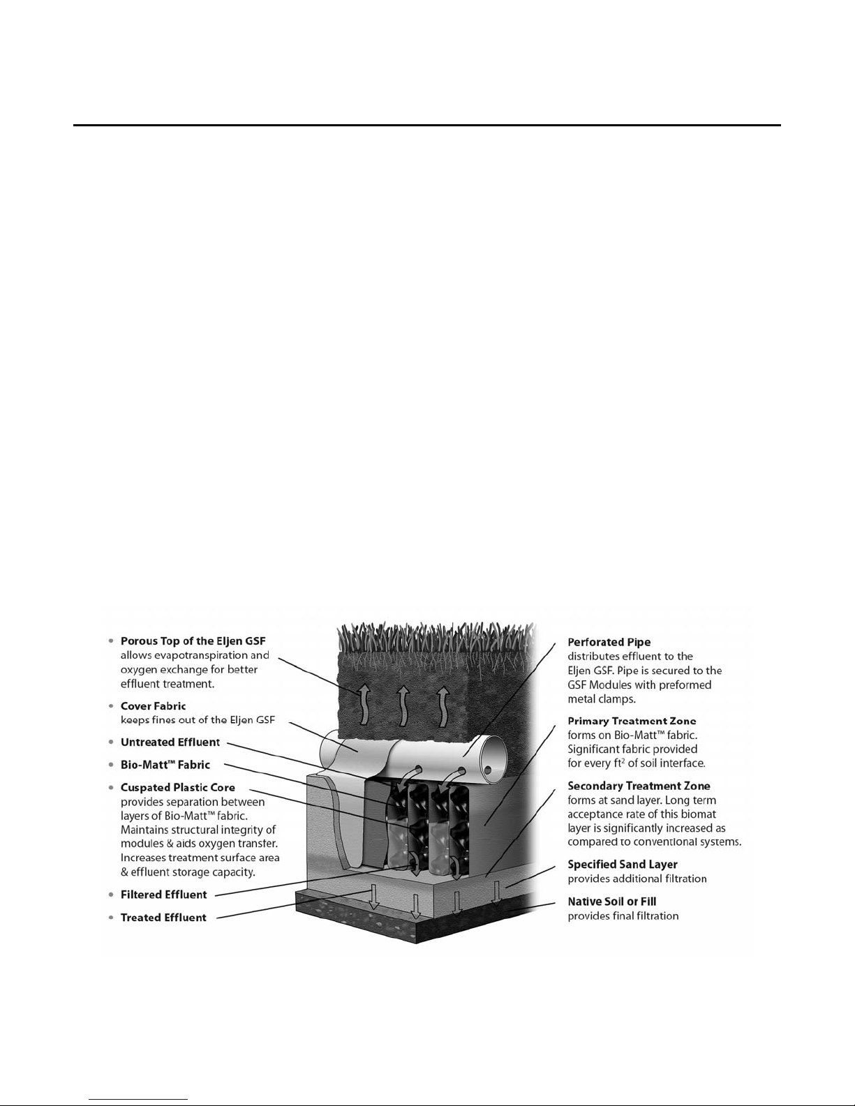
GSF SYSTEM DESCRIPTION ..................................................................................................................... 5
1.0 CONDITIONS FOR USE ........................................................................................................................ 6
1.1 SYSTEM DESIGN .................................................................................................................................. 6
2.0 SUBSURFACE TRENCH AND SINGLE LATERAL BED DESIGN AND INSTALLATION .................... 8
2.1 SUBSURFACE TRENCH AND SINGLE LATERAL BED DESIGN EXAMPLE ................................... 11
2.2 SUBSURFACE TRENCH AND SINGLE LATERAL BED DESIGN INSTALLATION STEPS .............. 13
3.0 SUBSURFACE BED DESIGN AND INSTALLATION .......................................................................... 15
3.1 SUBSURFACE BED DESIGN EXAMPLE ............................................................................................ 17
3.2 SUBSURFACE BED DESIGN INSTALLATION STEPS ...................................................................... 19
4.0 SLOPED SUBSURFACE BED DESIGN AND INSTALLATION ........................................................... 21
4.1 SLOPED SUBSURFACE BED DESIGN EXAMPLE ............................................................................ 23
4.2 SLOPED SUBSURFACE BED DESIGN INSTALLATION STEPS ...................................................... 26
5.0 ELEVATED SAND MOUND DESIGN AND INSTALLATION ............................................................... 28
5.1 ELEVATED SAND MOUND DESIGN EXAMPLE ................................................................................ 30
5.2 ELEVATED SAND MOUND INSTALLATION STEPS.......................................................................... 34
6.0 ABOVE GRADE BED DESIGN AND INSTALLATION ......................................................................... 35
6.1 ABOVE GRADE BED DESIGN EXAMPLE .......................................................................................... 37
6.2 ABOVE GRADE BED DESIGN INSTALLATION STEPS .................................................................... 39
7.0 SLOPED ABOVE GRADE BED DESIGN AND INSTALLATION ......................................................... 41
7.1 SLOPED ABOVE GRADE BED DESIGN EXAMPLE .......................................................................... 43
7.2 SLOPED ABOVE GRADE DESIGN INSTALLATION STEPS ............................................................. 46
8.0 DOSING DISTRIBUTION REQUIREMENTS ....................................................................................... 47
9.0 PRESSURE DISTRIBUTION REQUIREMENTS ................................................................................. 48
10.0 PUMP CONTROLS ............................................................................................................................ 50
11.0 SYSTEM VENTILATION .................................................................................................................... 50
12.0 INSPECTION/MONITORING PORT .................................................................................................. 51
13.0 INDIANA GSF REGISTRATION FORM ............................................................................................. 52
GSF DRAWINGS AND TABLES
DRAWINGS
FIGURE 1: GSF SYSTEM OPERATION .................................................................................................... 5
FIGURE 2: SEQUENTIAL LOADING DIAGRAM ......................................................................................... 7
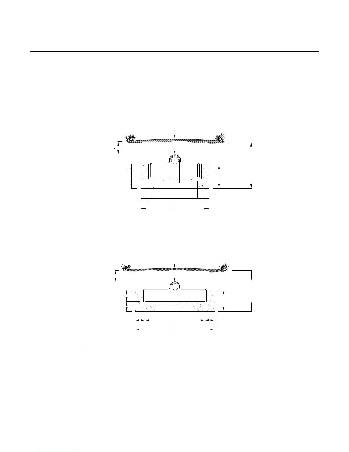
FIGURE 3: SUBSURFACE A42 TRENCH CROSS SECTION .................................................................... 8
FIGURE 4: SUBSURFACE B43 SINGLE LATERAL BED CROSS SECTION ............................................. 8
FIGURE 5: PLAN VIEW – 450 GPD – B43 –SINGLE LATERAL BED SYSTEM ......................................... 12
FIGURE 6: SECTION VIEW – B43 – SINGLE LATERAL BED SYSTEM – ≤ 0.5% SLOPE ........................ 12
FIGURE 7: SECTION VIEW – B43 – SINGLE LATERAL BED SYSTEM – 0.5 – 15% SLOPE .................. 12
FIGURE 8: SUBSURFACE BED CROSS SECTION ................................................................................. 15
FIGURE 9: PLAN VIEW – 600GPD – A42 – BED SYSTEM – ≤ 0.5% SLOPE ........................................... 18
FIGURE 10: CROSS SECTION VIEW – 600 GPD – A42 – BED SYSTEM – ≤ 0.5% SLOPE .................... 18
FIGURE 11: SUBSURFACE SLOPED BED CROSS SECTION ................................................................ 21
FIGURE 12: PLAN VIEW – 450 GPD – A42 – BED SYSTEM – 0.5 – 15% SLOPE .................................... 25
FIGURE 13: CROSS SECTION VIEW – 450 GPD – A42 – BED SYSTEM – 0.5 – 15% SLOPE ................ 25
FIGURE 14: ELEVATED SAND MOUND CROSS SECTION .................................................................... 28
FIGURE 15: CROSS SECTION – MOUND SYSTEM ................................................................................. 29
FIGURE 16: PLAN VIEW – MOUND SYSTEM .......................................................................................... 29
FIGURE 17: CROSS SECTION – MOUND SYSTEM ................................................................................. 33
FIGURE 18: PLAN VIEW – MOUND SYSTEM .......................................................................................... 33

2018 Indiana Design and Installation Manual 3 www.eljen.com
Table of Contents
FIGURE 19: PLAN VIEW – 600 GPD – APPLICATION AREA MOUND SYSTEM ..................................... 33
FIGURE 20: SUBSURFACE BED CROSS SECTION ............................................................................... 35
FIGURE 21: PLAN VIEW – 600GPD – A42 – BED SYSTEM – ≤ 0.5% SLOPE ......................................... 38
FIGURE 22: CROSS SECTION VIEW – 600 GPD – A42 – BED SYSTEM – ≤ 0.5% SLOPE ..................... 38
FIGURE 23: SLOPED ABOVE GRADE BED CROSS SECTION .............................................................. 41
FIGURE 24: PLAN VIEW – 450 GPD – A42 – BED SYSTEM – 0.5% - 6% SLOPE .................................... 45
FIGURE 25: CROSS SECTION VIEW – 450 GPD – A42 – BED SYSTEM – 0.5% - 6% SLOPE ................ 45
FIGURE 26: PRESSURE PIPE PLACEMENT ............................................................................................ 48
FIGURE 27: PRESSURE CLEAN OUT ..................................................................................................... 49
FIGURE 28: CONTOURED TRENCH INSTALLATION ............................................................................. 49
FIGURE 29: GSF WITH 4” VENT EXTENDED TO CONVENIENT LOCATION......................................... 50
FIGURE 30: MONITORING WELL FOR SAND-SOIL INTERFACE .......................................................... 51
TABLES
TABLE 1: SPECIFIED SAND SIEVE REQUIREMENTS ............................................................................. 4
TABLE 2: SYSTEM GUIDANCE CHART ..................................................................................................... 7
TABLE 3: GSF TRENCH AND SINGLE LATERAL BED SIZING CHART .................................................. 10
TABLE 4: GSF SUBSURFACE BED SIZING CHART ................................................................................ 16
TABLE 5: GSF SLOPED SUBSURFACE BED SIZING CHART ................................................................ 22
TABLE 6: N VALUE FOR MOUNDS ........................................................................................................... 30
TABLE 7: MINIMUM ELEVATED SAND MOUND BASAL AREA REQUIRED ........................................... 32
TABLE 8: GSF ABOVE GRADE BED SIZING CHART ............................................................................... 36
TABLE 9: GSF SLOPED ABOVE GRADE BED SIZING CHART ............................................................... 42

2018 Indiana Design and Installation Manual 4 www.eljen.com
Glossary of Terms
A42 Module 48” x 24” x 7” (L x W x H)
B43 Module 48” x 36” x 7” (L x W x H)
Cover Fabric The geotextile cover fabric (provided by manufacturer) that is placed over
the GSF modules. Barrier material cannot be substituted.
Design Flow The estimated peak flow that is used to size a GSF system is 150 gallons
per day per bedroom.
GSF Unit The Eljen Geotextile Sand Filter Modules and the minimum 6-inch (for
subsurface trench or bed) or minimum 12-inch (for above grade or
elevated sand mound) sand layer at the base and 6 inches along the sides
of the modules.
GSF Module The individual module of a GSF system. The module is comprised of a
cuspated plastic core and geotextile fabric.
Specified Sand To ensure proper system operation, the system MUST be installed using
Indiana Department of Transportation Specification 23 (INDOT SPEC 23)
sand AND must be used in accordance with ISDH Rule 410 IAC 6-8.3 (80)
(j) or ISDH Rule 410 6-10.1 (88) (j). Ask your material supplier for a sieve
analysis to verify that your material meets the required specifications.
Please place a prominent note to this effect on each design drawing.
TABLE 1: SPECIFIED SAND SIEVE REQUIREMENTS
INDIANA DEPARTMENT OF TRANSPORTATION
SPECIFICATION 23 SAND
Sieve Size Sieve Square
Opening Size
Specification
Percent Passing
(Wet Sieve)
3/8 inch 9.52 mm 100
No. 4 4.76 mm 95 - 100
No. 8 2.38 mm 80 - 100
No. 16 1.19 mm 50 - 85
No. 30 590 µm 25 - 60
No. 50 297 µm 5 - 30
No. 100 149 µm 0 - 10
No. 200 75 µm 0 - 3

2018 Indiana Design and Installation Manual 5 www.eljen.com
GSF System Description
Primary Treatment Zone
Perforated pipe is centered above the GSF module to distribute septic effluent over and into corrugations
created by the cuspated core of the geotextile module.
Septic effluent is filtered through the Bio-Matt (geotextile) fabric. The module’s unique design provides
increased surface area for biological treatment that greatly exceeds the module’s footprint.
Open air channels within the module support aerobic bacterial growth on the modules geotextile fabric
interface, surpassing the surface area required for traditional absorption systems.
A cover fabric covers the top and sides of the GSF module and protects the Specified Sand and soil
from clogging, while maintaining effluent storage within the module.
Secondary Treatment Zone
▪ Effluent drips into the Specified Sand layer and supports unsaturated flow into the native soil. This Specified
Sand/soil interface maintains soil structure, thereby maximizing the available absorption interface in the native
soil. The Specified Sand supports nitrification of the effluent, which reduces oxygen demand in the soil, thus
minimizing soil clogging from anaerobic bacteria.
The Specified Sand layer also protects the soil from compaction and helps maintain cracks and crevices
in the soil. This preserves the soil’s natural infiltration capacity, which is especially important in finer
textured soils, where these large channels are critical for long-term performance.
Native soil provides final filtration and allows for groundwater recharge.
FIGURE 1: GSF SYSTEM OPERATION

2018 Indiana Design and Installation Manual 6 www.eljen.com
1.0 Conditions for Use
1.0.1 ALTERATION OF MODULES: GSF modules shall not be altered by cutting or any other type of physical
modification.
1.0.2 WATER SOFTENER BACKWASH: Water softener backwash shall be discharged to a separate soil
absorption field meeting all required state codes and local regulations.
1.0.3 SEPTIC TANK OUTLET FILTERS: Eljen requires the use of outlet filters on all tanks including single
compartment tanks, up-sized tanks or when the dwelling has a garbage disposal installed.
1.0.4 GARBAGE DISPOSALS: Eljen discourages the use of garbage disposals with septic systems. If a GSF
system is to be designed and installed with garbage disposals the following measures must be taken to prevent
solids from leaving the tank and entering the GSF system:
Increase the septic tank capacity by a minimum of 30% or
Installation of a second septic tank installed in series if a multi-compartment tank isn’t used
1.0.5 ADDITIONAL FACTORS AFFECTING RESIDENTIAL SYSTEM SIZE: Homes with expected higher than
normal water usage may consider increasing the septic tank volume as well as incorporating a multiple compartment
septic tank. Consideration for disposal area may be up-sized for expected higher than normal water use.
For example:
Luxury homes, homes with a Jacuzzi style tubs, and other high use fixtures.
Homes with known higher than normal occupancy.
1.1 System Design
1.1.1 REQUIREMENTS: GSF systems must meet ISDH Rule 410 IAC 6-8.3 except as outlined in this manual.
The sizing tables in this manual applies to residential systems of any size and
Commercial systems with daily design flows less than or equal to 750 GPD
Sizing examples are found in this manual. Please contact Eljen’s Technical Resource Department at 1-800-444-
1359 for design information on commercial systems and adhere to ISDH Rule 410 6-10.1.
1.1.2 NUMBER OF GSF MODULES REQUIRED: The tables found in this manual indicate the minimum number
of A42 or B43 modules allowed. Systems can always be designed beyond the minimum required number of
modules. The minimum design requirements per 150 gpd are 6 A42 modules or 6 B43 modules.
1.1.3 SUITABLE SITE AND SOIL CONDITIONS: The Eljen Modules may be designed for all sites that meet the
criteria described in the Indiana State Department of Health, Residential Onsite Sewage Systems, Rule 410 IAC 6-
8.3 (70-73) or ISDH Rule 410 6-10.1 (78-80).
1.1.4 SEQUENTIAL LOADING: Sequential distribution may only be utilized for sloping sites. Sequential
Distribution uses a distribution box equipped with speed levelers. The uppermost line of the system and the inlet
to the distribution box will be left open. Down slope lines from the distribution box will have the speed leveler at 9
o’clock. Figure 2 demonstrates this practice which will fully utilize the uppermost section of the system prior to
spilling effluent into a lower row of modules. This is for use on any site with greater than 0.5% slope and parallel
distribution cannot be used. These systems are approved in writing on a case by case basis by the Eljen Technical
Department.

2018 Indiana Design and Installation Manual 7 www.eljen.com
1.1 System Design
FIGURE 2: SEQUENTIAL LOADING DIAGRAM
GSF MODULES
LOWEST TRENCH
GSF MODULES
LOWER TRENCHES
GSF MODULES
UPPER MOST TRENCH
THE LOWEST TRENCH ALONG THE SLOPE
DOES NOT REQUIRE A DISTRIBUTION BOX, ALTHOUGH
RECOMMENDED WITH COMMERCIAL DESIGNS
FOR INSPECTION AND OBSERVATION
THE INVER OF DIAL-A-FLOW "B"
IS SET AT THE 9:00 POSITION
DIAL-A-FLOW FITTINGS ARE NOT INSTALLED
ON THE OVER FLOW LINE FROM A UPPER
DISTRIBUTION BOX
OR THE DISTRIBUTION PIPE
LEADING TO THE GSF MODULES
BA
DIAL-A-FLOW
INVERT SETTING
THE INVER OF DIAL-A-FLOW "B"
IS SET AT THE 9:00 POSITION
DIAL-A-FLOW FITTINGS ARE NOT
INSTALLED ON THE OVER FLOW LINE
FROM THE SEPTIC TANK
OR THE DISTRIBUTION PIPE
LEADING TO THE GSF MODULES
BA
B
A
1.1.5 SYSTEM GUIDANCE The chart below directs you to the appropriate section of this manual for the design
and installation of the system.
TABLE 2: SYSTEM GUIDANCE CHART
Minimum Depth of
Installation from Existing
Grade
Number of
Laterals per
Excavation
Slope Section Page
10 Inches or Greater
Single 0 – 15% Subsurface Trench and
Sin
g
le Lateral Bed 11
Multiple 0.0 - 0.5% Subsurface Bed 15
0.5 – 15% Sloped Subsurface Bed 21
Existing Grade
Single 0 - 6% Elevated Sand Mound 28
Multiple 0.0 - 0.5% Above Grade Bed 35
0.5 – 6% Sloped Above Grade Bed 41
Use the section above to go to the correct portion of this manual.

2018 Indiana Design and Installation Manual 8 www.eljen.com
2.0 Subsurface Trench and Single Lateral Bed Design and Installation
2.0.1 ACCEPTABLE METHODS OF DISTRIBUTION: Gravity, dosed and pressure distribution are acceptable.
2.0.2 MINIMUM DEPTH FROM ORIGINAL GRADE FOR SUBSURFACE SYSTEMS: The minimum depth for
subsurface systems is 10 inches from original grade to the sand/soil interface for the system.
2.0.3 GENERAL CROSS SECTIONS
FIGURE 3: SUBSURFACE A42 TRENCH CROSS SECTION
SPECIFIED SAND
GEOTEXTILE FABRIC
FINAL GRADE
13"
36"
6"24"6"
6"
7"
MIN 12" OF
COVER SOIL
MATERIAL
MAXIMUM
TRENCH
DEPTH 36"
FIGURE 4: SUBSURFACE B43 SINGLE LATERAL BED CROSS SECTION
SPECIFIED SAND
GEOTEXTILE FABRIC
FINAL GRADE
13"
48"
6"36"6"
6"
7"
MIN 12" OF
COVER SOIL
MATERIAL
MAXIMUM
TRENCH
DEPTH 36"
All subsurface trenches and single lateral beds are required to have:
6 inches of Specified Sand at the edges of the GSF module.
6 inches of Specified Sand at the beginning and end of each GSF Row.
Minimum 6 inches of Specified Sand directly below the GSF module.
Minimum 12 inches of cover soil material above the 4-inch distribution pipe.
Maximum trench or single lateral bed depth from final grade is 36 inches.

2018 Indiana Design and Installation Manual 9 www.eljen.com
2.0 Subsurface Trench and Single Lateral Bed Design and Installation
2.0.4 VERTICAL SEPARATION TO SEASONAL HIGH-WATER TABLE OR LIMITING LAYER: Refer to section
Rule 410 IAC 6-8.3 70.b.5 for subsurface absorption systems or ISDH Rule 410 6-10.1 (61).
V
ertical Separation Distance
(
VSD
)
System Type Daily Design Flow Limiting
La
y
er
Seasonal High
Water Table
Subsurface Trench and Single Lateral
Bed System
>450 30” 24”
<450 24”
Pressure Distribution Any 24” 24”
VSD measured from the bottom of the excavated trench or bed for the subsurface s
y
stem.
2.0.5 DISTRIBUTION BOX: Parallel distribution is preferred. Sequential distribution may be utilized for sloping
sites and must conform to 1.1.4. Distribution boxes are required to be 5 feet from the proximal end of each soil
absorption field trench.
2.0.6 PARALLEL DISTRIBUTION: Parallel distribution is the preferred method of application to a gravity or pump
to gravity system. It encourages equal flows to each of the lines in the system. It is recommended for most trench
systems.
2.0.7 TRENCH LENGTH: Trenches will have a maximum of 100 ft in length unless pressure distribution is used per
410 IAC 6-8.3 (74) (r) or ISDH Rule 410 6-10.1 (82) (r).
2.0.8 EQUAL LENGTH: Trenches must be of equal length in order to provide equal distribution.
2.0.9 SPACING GUIDANCE BETWEEN TRENCHES AND SINGLE LATERAL BED ROWS: Ensure trenches are
of equal length throughout the system. If using the B43 in a single lateral bed system, ensure there is center to
center distance of 10 feet and 7.5 feet center to center distance for the A42 in a trench.
2.0.10 DISPERSAL AREA: Dispersal area requirements are located in IAC 6-8.3 (58) or ISDH Rule 410 6-10.1
(62).
2.0.11 MINIMUM SLOPE REQUIREMENTS: Maintain a 3:1 slope or gentler for all slopes off the application area.
2.0.12 SUBSURFACE DRAINS: If subsurface drains are utilized they must remain 10 feet from the edge of the
system sand perimeter.

2018 Indiana Design and Installation Manual 10 www.eljen.com
2.0 Subsurface Trench and Single Lateral Bed Design and Installation
2.0.13 SIZING GSF SYSTEMS:
TABLE 3: GSF TRENCH AND SINGLE LATERAL BED SIZING CHART
Soil
Loading
Rate
(gpd/sf)
Minimum Absorption Area
Required (Square Feet) A42 Modules per House B43 Modules per House
Bedrooms per House Bedrooms per House Bedrooms per House
3 4 5 3 4 5 3 4 5
1.2 252 335 419 21 28 35 18 24 30
0.75 402 536 670 34 45 56 26 34 42
0.6 503 670 838 42 56 70 32 42 53
0.5 603 804 1005 51 67 84 38 51 63
0.3 1005 1340 1675 84 112 140 63 84 105
0.25 1206 1608 2010 101 134 168 76 101 126
Notes:
The Minimum Absorption Area has been adjusted to reflect a 33% reduction in absorption field area.
Any jetted bath tub with a capacity greater than 125 gallons will be treated as an extra bedroom for the system sizing requirements per Rule
410 IAC 6-8.3.
A42 Modules have an effective area of 12 ft2/mod. B43 Modules have an effective area of 16 ft2/mod.

2018 Indiana Design and Installation Manual 11 www.eljen.com
2.1 Subsurface Trench and Single Lateral Bed Design Example
Example 1: Subsurface Trench (A42 Module) and Single Lateral Bed System (B43 Module)
House size: 3 Bedrooms
Design Flow: 450 gpd
Soil Loading Rate: 0.3 gpd/ft2
Absorption Field Type: Trench
Calculate Minimum Basal Area and Units Required
Refer to Table 3 for the minimum number of units and minimum sized basal area required for installation.
Calculate Minimum Trench Length
A42: 84 units x 4 ft/unit = 336 linear ft B43: 63 units x 4 ft/unit = 252 linear ft
Trench Width
A42: 3 ft B43: 4 ft
Final Dimension Layout
(Note: System layout and number of rows will vary based on site constraints)
A42 – Trench
Min. Product Length 336 ft
(note: 6 inches sand required at each end of trench
which makes the minimum trench length 337 ft)
Trench Width 3 ft
Minimum Number of Units 84 A42 Modules
Designed Absorption Area 1,011 ft2
B43 – Single Lateral Bed
Min. Product Length 252 ft
(note: 6 inches sand required at each end of trench
which makes the minimum trench length 253 ft)
Trench Width 4 ft
Minimum Number of Units 63 B43 Modules
Designed Absorption Area 1,012 ft2
345345345
0.3 1005 1340 1675 84 112 140 63 84 105
Soil
Loading
Rate
(gpd/sf)
Bedrooms per House Bedrooms per House Bedrooms per House
Minimum Absorption Area
Required (Square Feet) A42 Modules per House B43 Modules per House

2018 Indiana Design and Installation Manual 12 www.eljen.com
2.1 Subsurface Trench and Single Lateral Bed Design Example
FIGURE 5: PLAN VIEW – 450 GPD – B43 –SINGLE LATERAL BED SYSTEM
NATIVE SOIL
DISTRIBUTION BOX
(MIN 5 FT FROM FIELD)
SPECIFIED SAND
4'
MIN 10'
3'
85'
84'
FIGURE 6: SECTION VIEW – B43 – SINGLE LATERAL BED SYSTEM – ≤ 0.5% SLOPE
48"
36"
GEOTEXTILE
FABRIC
FINAL GRADE
SPECIFIED SAND
7"
6"
MIN 12" OF
COVER SOIL
MATERIAL
48"
NATIVE SOIL
6' MIN
SPECIFIED SAND
48"
NATIVE SOIL
6' MIN
SPECIFIED SAND
Loading Rate 0.3 gpd/ft2, Design Flow 150 gpd x 3 Bedrooms = 450 gallons per day.
(21 Modules per Row)
FIGURE 7: SECTION VIEW – B43 – SINGLE LATERAL BED SYSTEM – 0.5 – 15% SLOPE
FINAL GRADE
7"
6"
MIN 12" OF
SOIL COVER
MATERIAL
NATIVE SOIL
6' MIN
GEOTEXTILE
FABRIC
SPECIFIED SAND
SPECIFIED SAND
48"
36"
48"
NATIVE SOIL
6' MIN
SPECIFIED SAND
48"
Loading Rate 0.3 gpd/ft2, Design Flow 150 gpd x 3 Bedrooms = 450 gallons per day.
(21 Modules per Row)

2018 Indiana Design and Installation Manual 13 www.eljen.com
2.2 Subsurface Trench and Single Lateral Bed Design Installation Steps
1. Ensure all components leading to the GSF system are installed properly. Outlet filters are required with the
GSF system. Connections of lines to tanks and distribution boxes must follow requirements of 410 IAC 6-8.3
or ISDH Rule 410 6-10.1.
2. Determine the number of GSF Modules required using Table 3.
3. Prepare the site. Do not install a system in saturated ground or wet soils that are smeared during excavation.
Keep machinery off infiltrative areas. Refer to IAC 6-8.3 or ISDH Rule 410 6-10.1 for all site preparation
requirements prior to site construction.
4. Plan all drainage requirements above (up-slope) of the system. Set soil grades to ensure that storm water
drainage and ground water is diverted away from the absorption area once the system is complete. All drainage
requirements shall be in accordance with 410 IAC 6-8.3 (59) or 410 6-10.1 (63).
5. Excavate the trench absorption area; scarify the receiving layer to maximize the interface between the native
soil and specified sand.
6. Minimize walking in the trench prior to placement of the specified sand to avoid soil compaction.
7. Place a minimum of 6 inches of Specified Sand in the absorption area and stabilize level. The first 6 inches of
sand immediately under and around the perimeter of the GSF system must be INDIANA DEPARTMENT OF
TRANSPORTATION (INDOT) SPECIFICATION 23 SAND. See Table 1 for more information on the sand and
sieve specifications.
8. Place GSF modules with PAINTED STRIPE FACING UP. Each row of modules is laid level in its length and
width, end to end, along their four-foot length on the Specified Sand layer. No mechanical connection is
required between modules.
9. A standard 4-inch perforated pipe, SDR 35 or equivalent is centered along the modules 4-foot length. Orifices
are set at the 4 & 8 o’clock position. All distribution piping must meet the requirements of ISDH Rule 410 6-8.3
Section 67 or ISDH Rule 410 6-10.1 Section 75.
10. All 4-inch pipes are secured with manufacturers supplied wire clamps, one per module.
11. (Pressure Distribution Systems) Insert a Sch. 40 pressure pipe which meets 410 IAC 6-8.3 (67) or ISDH Rule
410 6-10.1 (75), into the standard 4-inch perforated pipe. The pressure pipe orifices are set at the 12 o’clock
position as shown in Figure 26. Each pressure lateral will have a drain hole at the distal end of the lateral at
the 6 o’clock position. Each pressure lateral shall have a clean out at the end of the trench.
12. The 4-inch distribution pipe shall be capped or vented.
13. Cover fabric substitution is not allowed. The installer should lay the Eljen provided geotextile cover fabric
lengthwise down the trench, with the fabric fitted to the perforated pipe on top of the GSF modules. Fabric
should be neither too loose, nor too tight. The correct tension of the cover fabric is set by:
a. Spreading the cover fabric over the top of the module and down both sides of the module with the
cover fabric tented over the top of the perforated distribution pipe.
b. Place shovelfuls of Specified Sand directly over the pipe area allowing the cover fabric to form a
mostly vertical orientation along the sides of the pipe. Repeat this step moving down the pipe.
14. Place 6 inches of Specified Sand along both sides of the modules edge. A minimum of 6 inches of Specified
Sand is placed at the beginning and end of each trench.

2018 Indiana Design and Installation Manual 14 www.eljen.com
2.2 Subsurface Trench and Single Lateral Bed Design Installation Steps
15. Complete backfill with cover soil material to a minimum of 12 – 19 inches measured from the top of the 4-inch
distribution pipe. Fill must be clean, porous and able to sustain vegetation. Do not use wheeled equipment
over the system during backfill operation. A light track machine may be used with extreme caution, avoiding
crushing or shifting of pipe assembly.
16. Divert surface runoff from the system. Finish grade to prevent surface ponding. Topsoil and seed system area
to protect from erosion.

2018 Indiana Design and Installation Manual 15 www.eljen.com
3.0 Subsurface Bed Design and Installation
3.0.1 ACCEPTABLE METHODS OF DISTRIBUTION: Gravity, dosed and pressure distribution are acceptable.
3.0.2 MINIMUM DEPTH FROM ORIGINAL GRADE FOR SUBSURFACE SYSTEMS: The minimum depth for
subsurface systems is 10 inches from original grade. That is the start of the sand/soil interface for the system.
3.0.3 GENERAL CROSS SECTION
FIGURE 8: SUBSURFACE BED CROSS SECTION
SPECIFIED SAND
12" MIN - 19" MAX
OF COVER SOIL
MATERIAL
13"
ORIGINAL GRADE
FINAL GRADE
All subsurface bed systems are required to have a minimum of:
6 inches of Specified Sand at the edges of the GSF module.
6 inches of Specified Sand at the beginning and end of each GSF Row.
6 inches of Specified Sand directly below the GSF module.
Minimum 12 inches of cover soil material above the 4-inch distribution pipe
Maximum excavation depth from final grade is 36 inches.
3.0.4 VERTICAL SEPARATION TO SEASONAL HIGH-WATER TABLE OR LIMITING LAYER: Refer to section
Rule 410 IAC 6-8.3 70.b.5 for subsurface absorption systems or ISDH Rule 410 6-10.1 (61).
V
ertical Separation Distance
(
VSD
)
System Type Daily Design Flow Limiting
La
y
er
Seasonal High-Water
Table
Subsurface Bed >450 30” 24”
<450 24”
Pressure Distribution Any 24” 24”
VSD measured from the bottom of the excavated bed for the subsurface s
y
stem.
3.0.5 DISTRIBUTION BOX: Parallel distribution is preferred. Sequential distribution may be utilized for sloping
sites and must conform to 1.1.4. Distribution boxes are recommended to be 5 feet from the proximal end of each
soil absorption field row as per Rule 410 IAC 6-8.3 Section 75.i or ISDH Rule 410 6-10.1 Section 74. This may be
amended to shorter distance per the designer.
3.0.6 PARALLEL DISTRIBUTION: Parallel distribution is the preferred method of application to a gravity or pump
to gravity system. It encourages equal flows to each of the lines in the system. It is recommended for most bed
systems.
3.0.7 ROWS REQUIRED: All bed systems shall have a minimum of two rows of modules.
3.0.8 ROW LENGTH: Rows will have a maximum of 100 ft in length unless pressure dosed per 410 IAC 6-8.3 (74)
(r) or ISDH Rule 410 6-10.1 (82) (r).
3.0.9 EQUAL LENGTH: Rows must be of equal length in order to provide equal distribution.

2018 Indiana Design and Installation Manual 16 www.eljen.com
3.0 Subsurface Bed Design and Installation
3.0.10 DISPERSAL AREA: Dispersal area requirements are located in IAC 6-8.3 (58) or ISDH Rule 410 6-10.1
(62).
3.0.11 MINIMUM SLOPE REQUIREMENTS: Maintain a 3:1 slope or gentler for all slopes off the application area.
3.0.12 SUBSURFACE DRAINS: If subsurface drains are utilized they must remain 10 feet from the edge of the
system sand perimeter.
3.0.13 SIZING GSF SYSTEMS:
TABLE 4: GSF SUBSURFACE BED SIZING CHART
Soil
Loading
Rate
(gpd/sf)
Minimum Basal Area
Required (Square Feet) A42
Modules
per Room
B43
Modules
per Room
Bedrooms per House
3 4 5
1.2 252 335 419 6 6
0.75 402 536 670 8 7
0.6 503 670 838 9 8
0.5 603 804 1005 11 9
0.3 1005 1340 1675 12 10
0.25 1206 1608 2010 13 11
Notes:
The Minimum Basal Areas have been adjusted to reflect a 33% reduction in absorption field area.
Any jetted bath tub with a capacity greater than 125 gallons will be treated as an extra bedroom for the system sizing requirements per Rule
410 IAC 6-8.3.
3.0.14 SYSTEM LENGTH AND WIDTH: Best engineering practices should be used when construction the bed
systems. Rule IAC 6-8.3 (79) (2) and ISDH Rule 410 6-10.1 (87) (b) states the dimensions of the bed shall be as
long and narrow as the site allows.
3.0.15 BED DESIGN: For beds with less than a 0.5% slope, evenly distribute the bed laterals in the basal area. A
minimum separation distance between laterals for A42’s is 3’ and a minimum separation distance between laterals
of 4’ for B43’s.

2018 Indiana Design and Installation Manual 17 www.eljen.com
3.1 Subsurface Bed Design Example
Example 2: Subsurface Bed System – A42 Modules – 0.0 – 0.5% Slope
House size: 4 Bedrooms
Design Flow: 600 gpd
Soil Loading Rate: 0.3 gpd/ft2
Absorption Field Type: Bed
Site Slope: Less than 0.5%
Calculate Minimum Basal Area and Units Required
Refer to Table 4 for the minimum number of units and minimum basal area required for installation.
Units required per bedroom x bedrooms = Total units required
A42: 12 units/bedroom x 4 bedrooms = 48 A42s B43: 10 units/bedroom x 4 bedrooms = 40 B43s
Calculate Minimum Bed Basal Area Length
For This Example, Assume the Number of Bed Rows Equals Two (this encourages the longest and
narrowest subsurface bed design):
Modules per row: Modules Needed ÷ Rows
A42: 48 units ÷ 2 rows = 24 modules per row
A42: 24 units x 4 ft/unit +1 ft = 97 linear ft
B43: 40 units ÷ 2 rows = 20 modules per row
B43: 20 units x 4 ft/unit +1 = 81 linear ft
Calculate Bed Basal Area Width
a) Minimum A42 Basal Area Width
a) A42: Rows x 3 ft = 2 x 3 ft = 6 ft
or
b) Proposed Basal Area Width
b) Minimum Basal Area ÷ Length of System
b) A42: 1340 ft2 ÷ 97 ft = 13.8 ft,
b) round to 14 ft
A42: Use greater width of a or b: 14 ft
a) Minimum B43 Basal Area Width
a) B43: Rows x 4 ft = 2 x 4 ft = 8 ft
or
b) Proposed Basal Area Width
b) Minimum Basal Area ÷ Length of System
b) B43: 1340 ft2 ÷ 81 ft = 16.5 ft,
b) round to 17 ft
B43: Use greater width of a or b: 17 ft
Determine Lateral Spacing
Lateral to Lateral Spacing = Bed Width ÷ Rows
A42: 14 ft ÷ 2 rows = 7 ft B43: 17 ft ÷ 2 rows = 8.5 ft
Upper Edge to Lateral Spacing = Lateral to Lateral Spacing ÷ 2
A42: 7 ft ÷ 2 = 3.5 ft B43: 8.5 ft ÷ 2 = 4.25 ft
345
0.3 1005 1340 1675 12 10
Soil
Loading
Rate
(gpd/sf)
Minimum Basal Area Required
(Square Feet)
Bedrooms per House
A42
Modules per
Room
B43
Modules per
Room
A42 B43 A42 B43
Slope Lateral to Lateral SpacingUpper Edge to Lateral Spacing
Lessthanor
Equalto0.5%
Lateral to Lateral Spacing ÷ 2 Basal Area width divided by
number of rows

3.1 Subsurface Bed Design Example
Final Dimension Layout
(Note: System layout and number of rows will vary based on site constraints)
A42
Basal Area Length: 97 ft
Basal Area Width: 14 ft
Minimum Number of Units: 48 A42 Modules
Center to Center Spacing: 7 ft
Edge to Center Spacing: 3.5 ft
Designed Basal Area: 1,358 ft2
B43
Bed Length: 81 ft
Bed Width: 17 ft
Minimum Number of Units: 40 B43 Modules
Center to Center Spacing: 8.5 ft
Edge to Center Spacing: 4.25 ft
Designed Basal Area: 1,377 ft2
FIGURE 9: PLAN VIEW – 600GPD – A42 – BED SYSTEM – ≤ 0.5% SLOPE
SPECIFIED SAND
97'
96'
14'
3' 6"
7' DISTRIBUTION BOX
FIGURE 10: CROSS SECTION VIEW – 600 GPD – A42 – BED SYSTEM – ≤ 0.5% SLOPE
SPECIFIED SAND
3.5'7'3.5'
12" MIN - 19" MAX
OF COVER SOIL
MATERIAL
14'
13"
ORIGINAL GRADE
FINAL GRADE

2018 Indiana Design and Installation Manual 19 www.eljen.com
3.2 Subsurface Bed Design Installation Steps
1. Ensure all components leading to the GSF system are installed properly. Outlet filters are required with the
GSF system. Connections of lines to tanks and distribution boxes must follow requirements of 410 IAC 6-8.3
or ISDH Rule 410 6-10.1.
2. Determine the number of GSF Modules required using Table 4.
3. Prepare the site. Do not install a system in saturated ground or wet soils that are smeared during excavation.
Keep machinery off infiltrative areas. Refer to IAC 6-8.3 or ISDH Rule 410 6-10.1, for all site preparation
requirements prior to site construction.
4. Plan all drainage requirements above (up-slope) of the system. Set soil grades to ensure that storm water
drainage and ground water is diverted away from the system once it is complete. All drainage requirements
shall be in accordance with 410 IAC 6-8.3 (59).
5. Excavate the bed basal area; scarify the receiving layer to maximize the interface between the native soil and
specified sand.
6. Minimize walking in the excavated area prior to placement of the specified sand to avoid soil compaction.
7. Place a minimum of 6 inches of Specified Sand in the basal area and stabilize level. The first 6 inches of sand
immediately under and around the perimeter of the GSF system must be INDIANA DEPARTMENT OF
TRANSPORTATION (INDOT) SPECIFICATION 23 SAND. See Table 1 for more information on the sand and
sieve specifications.
8. Place GSF modules with PAINTED STRIPE FACING UP. Each row of modules is laid level in its length and
width, end to end, along their four-foot length on the Specified Sand layer. No mechanical connection is
required between modules.
9. A standard 4-inch perforated pipe, SDR 35 or equivalent is centered along the modules 4-foot length. Orifices
are set at the 4 & 8 o’clock position. All distribution piping must meet the requirements of ISDH Rule 410 6-8.3
Section 67 or ISDH Rule 410 6-10.1 Section 75.
10. All 4-inch pipes are secured with manufacturers supplied wire clamps, one per module.
11. (Pressure Distribution Systems) Insert a Sch. 40 pressure pipe which meets 410 IAC 6-8.3 (67) or ISDH Rule
410 6-10.1 (75), into the standard 4-inch perforated pipe. The pressure pipe orifices are set at the 12 o’clock
position as shown in Figure 26. Each pressure lateral will have a drain hole at the distal end of the lateral at
the 6 o’clock position. Each pressure lateral shall have a clean out at the end of the row.
12. The distribution pipe shall be capped or vented.
13. Cover fabric substitution is not allowed. The installer should lay the Eljen provided geotextile cover fabric
lengthwise down the row, with the fabric fitted to the perforated pipe on top of the GSF modules. Fabric should
be neither too loose, nor too tight. The correct tension of the cover fabric is set by:
a. Spreading the cover fabric over the top of the module and down both sides of the module with the
cover fabric tented over the top of the perforated distribution pipe.
b. Place shovelfuls of Specified Sand directly over the pipe area allowing the cover fabric to form a
mostly vertical orientation along the sides of the pipe. Repeat this step moving down the pipe.
14. Place 6 inches of Specified Sand along both sides of the modules edge. A minimum of 6 inches of Specified
Sand is placed at the beginning and end of each module row. A minimum of 12 inches of Specified Sand is
placed in between module rows.

2018 Indiana Design and Installation Manual 20 www.eljen.com
3.2 Subsurface Bed Design Installation Steps
15. Complete backfill with cover soil material to a minimum of 12 – 19 inches measured from the top of the 4-inch
distribution pipe. Fill must be clean, porous and able to sustain vegetation. Do not use wheeled equipment
over the system during backfill operation. A light track machine may be used with extreme caution, avoiding
crushing or shifting of pipe assembly.
16. Divert surface runoff from the system. Finish grade to prevent surface ponding. Topsoil and seed system area
to protect from erosion.
This manual suits for next models
1
Table of contents