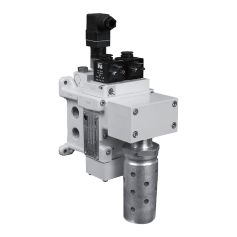
HDBH Series Operating Instructions
4www.rosscontrols.com
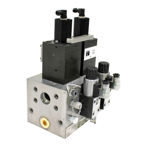
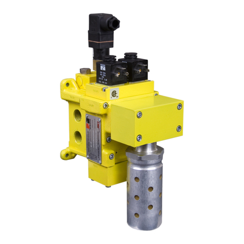
The safety function of the HDBH Series Dual Block & Stop system is to only supply
ow into and out of a cylinder or designated portion of the hydraulic machine/system
when the two valve elements are actuated simultaneously, but to block the ow in
both directions in both cylinder lines when both valves are shut-off or if only one of
the two valves is de-actuated. A fault in the system where only one valve actuates
when switching on or only one de-actuates when switching off prevents ow of oil from
moving downstream or upstream in both ports. Monitoring of the two inductive position
switches by the user’s external safety control & monitoring system makes it possible to
detect these fault situations and to shut off and prevent further electrical energization
of the solenoids.
Port identication on the manifold according to ISO 16874
The HDBH Series Dual Block & Stop system is designed and manufactured in
accordance with the identication requirements laid out in the ISO 16874:2004
standard.
6.1.2. Common Cause Failure – CCF
The product has been engineered and manufactured according to the fundamental
and proven safety principles of ISO 13849-1:2015 and -2:2012.
Common Cause Failures (CCF) are failures of different components, resulting from
a single event. CCF are not to be confused with cascading faults or common mode
faults. Common cause failures can cause loss of the safety function, especially in dual
channel circuits where both channels could fail simultaneously due to a single event.
6.1.3. Critical failure modes and causes:
• Failure of the safety function - caused by simultaneous incomplete return of both
solenoid valves (1A and 1B).
• Maintain hydraulic oil quality, i.e., proper ltration.
• Operate within prescribed temperature limits.
• Install the valve such that the normal stroke travel of the valve elements is
perpendicular to the main direction of machine vibration and/or mechanical shock.
• Do not use a test pulse longer than recommended by the HDBH Integration Guide.
• Avoid external magnetic elds.
6.1.4. Diagnostic Coverage
A diagnostic coverage of 99% is achievable through appropriate integration of the
HDBH Series Dual Block & Stop system into the safety control system. The monitoring
system must check for the proper change of state of each valve’s inductive position
switch (Switch 1A and 1B) with each change of state of the safety control system
outputs to the valve solenoids (Sol 1A and 1B). Detection of a fault by the safety control
& monitoring system must trigger a shut-off of the safety controller’s outputs to the
valve solenoids (Sol 1A and 1B).
6.1.5. Fault Modes
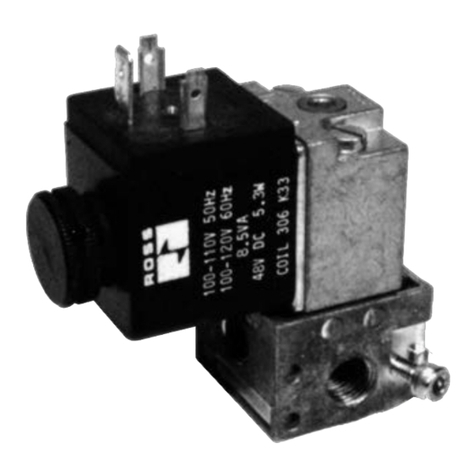
Note that normal operation requires that Sol 1A and 1B be energized simultaneously for
switching the HDBH system on, and de-energizing both Sol 1A and 1B simultaneously
for switching the HDBH system off.
NOTE: The switches are supplied with both NC and NO contacts. The statements
below only refer to whether or not the switches are actuated.
Faults that could occur during normal operation are:
Sol 1A and 1B energized simultaneously
Switch 1A ON, Switch 1B OFF
Switch 1A OFF, Switch 1B ON
Switch 1A OFF, Switch 1B OFF
Sol 1A and 1B de-energized simultaneously
Switch 1A ON, Switch 1B OFF
Switch 1A OFF, Switch 1B ON
Switch 1A ON, Switch 1B ON
6.1.6. Foreseeable Misuse
WARNING
Risk of Injury!
Misuse may result in injury or damage.
fThe product must be used exclusively as intended.
Foreseeable misuse includes:
• Bypassing the safety function or diagnostics.
• Replacing the safety valves with unauthorized valves.
• Tampering with the position switches.
• Failing to utilize the position switches to verify valve operation on every cycle -
when energizing and de-energizing.
• Allowing continued operation of the valve when one or both valve shifted signals
(from position switches) are not conrmed.
• Operating at pressures above maximum operating pressure.
6.2. Responsibilities of the System Owner
Observation of general requirements pertaining to hazards:
• Unusual noises, vibration, defects or damage is to be remedied immediately as it
may point to potential hazards.
• Generally speaking, no maintenance work may be done on the hydraulic system
and power units as long as they are under hydraulic pressure or the power supply
has not been switched off.
• Prior to performing any maintenance work, pressure accumulators are to be
depressurized.
• The hydraulic system has to be depressurized at any time work is done on the gas
side of an accumulator.
• Note the load pressures present. Also note any loads applied. If necessary, make
sure that the loads are secured or properly supported.
• Hydraulic systems may only be operated by properly trained and instructed
personnel.
• All safety devices and equipment are to be checked to see that they function properly.
• Safety devices and equipment may not be removed, deactivated or circumvented
owing to the accident hazard posed by this action.
• General safety and accident prevention regulations pertaining to operating the unit/
system are to be adhered to.
• Comply with the further requirements of ISO 13849 (e. g., MTTFD, CCF, DC, PLr,)
if you intend to use the product in higher categories (2 to 4).
• Check the valve at least once a month to ensure its proper operation.
• Make sure that the fundamental and proven safety principles in accordance with
ISO 13849 for implementation and operation of the component are complied with.
• Selection and installation of replacement valves must take place in accordance
with the manufacturer’s specications.
6.3. Safety Instructions
The HDBH Series Dual Block & Stop System features a state-of-the-art design.
Reliable and safe operation cannot be ensured unless all the instructions, settings and
output limits applicable to the unit supplied are adhered to.
The systems involved are pressure-generating systems whose components feature
pressurized liquid; consequently, the systems may pose a hazard if not dealt with
properly.
6.3.1. Additional Safety Considerations
• When implementing surge suppression measures, be sure to check whether or
not this extends the valve system shut off response time which could extend the
machine stopping time.
• In case of high levels of machine vibration, use appropriate vibration-reducing
elements when installing the valve system.
• Supply the proper voltage as overvoltage situations can result in solenoid
burnout.
7. Assembly and Installation
CAUTIONS
Risk of injury due to installation while pressurized or with live parts!
fInstallation while pressurized or with electrical power switched on can result in injuries due to
sudden pressure build-up or electric shock.
fDe-energize and de-pressurize the relevant system parts before installing the valves.
fSecure the system to prevent it from being switched back on again.
ATTENTION
Destruction of components!
Chemical substances can damage the surface, the markings and the seals of the device.
fInstall the valve such that it is protected against the effects of chemicals.
Damage to the device through storage at incorrect temperatures!
The storage temperature represents the permissible ambient temperature and depends on the
type of valve in question.
fObserve the temperature information in chapter 10 “Technical Data.”
7.1. Installation Instructions
Secure the system using the through holes in the manifold. Refer to pattern for the
required dimensions, - see dimensional drawings on page 2.
7.1.1. Component Inspection: Prior to use, a careful examination of
the HDBH valve system must be performed. The HDBH valve system must be
checked for correct style, size, catalog number and external condition, and must
be examined for cleanliness, absence of external defects or gouges or otherwise
deformed parts or other imperfections. DO NOT use any item that displays any signs
of nonconformance. Any accessory including, but not limited to, ttings, bolt kits,
hoses, sub-bases, manifolds and electrical connectors must be subjected to the
same examination.
