AAF SAAF PORTA-Scrubber PS-200 Manual

SAAF™PORTA-Scrubber
Installation, Operation, and Maintenance Instructions
1.0 Introduction
1.1 About This Document
This document contains the information necessary to properly
receive, assemble, install, operate, and maintain the SAAFTM
PORTA-Scrubber filtration system. The purchaser, installer, and/or
operator of the filtration system MUST read and comply with this
document in its entirety prior to installation of the equipment and its
operation. Failure to comply with the requirements of this manual
may void the product warranty.
CAUTION: These instructions are specific to the SAAF PORTA-
Scrubber and SAAF Chemical Filtration Media. All ancillary tasks
including, but not limited to, electrical and mechanical work,
equipment handling, and safety procedures must be performed in
accordance with industry accepted practice and all relevant local,
state, and federal government codes, laws, and policies.
Better Air is Our Business®
Table of Contents
1.0 Introduction
1.1 About this document
1.2 Packaging and shipping, receiving and inspection,
handling and storage
1.3 Product descriptions
1.4 Product model designations
1.5 Product drawings
1.6 Assembly – general comments
1.7 Related system equipment
2.0 Principles of Operation
3.0 Installation Instructions
3.1 Space requirements
3.2 Foundations and anchoring
3.3 Typical PORTA-Scrubber details
3.4 General filter system installation
3.5 Preparation for filter installation
3.6 PolyKleanTM Blue filter installation
3.7 Gas phase chemical media installation
3.8 Cover latches
3.9 Fans
3.10 Standard Motors
4.0 Start-up Instructions
5.0 Maintenance
5.1 PolyKlean Blue filter
5.2 Gas phase chemical media monitoring
5.3 Removal and replacement of particulate and gas phase
chemical media
5.4 Disposal of used filters
5.5 Cover sealing gaskets
5.6 General system maintenance
6.0 Troubleshooting
7.0 Spare Parts List
8.0 Equipment Characteristics, Operating Weights, and
Shipping Weights

2
1.2 Packaging and Shipping, Receiving and Inspection, Handling
and Storage
1.2.1 Packaging and Shipping: Unless otherwise defined in the
purchase order and agreed by AAF, the PORTA-Scrubber and
filters are packaged for domestic transit and shipped FOB the
AAF factory. The method of shipment will be as specified in the
customer’s purchase order to AAF.
1.2.2 Receiving and Inspection: Obtain a copy of the
purchase order and product drawing that was submitted by AAF
in association with the order, and a copy of the bill of lading, along
with any other shipping papers. Upon receipt of the equipment, or
any part thereof, these documents shall be used to ensure that the
correct product has been received.
For maximum protection, complete the following steps upon receipt
of the PORTA-Scrubber and chemical media:
• Inspect the shipment and all associated documentation. Notify
the carrier immediately if there is any visible damage to the
packaging or the equipment, or a discrepancy in the shipping
papers. If necessary, file an immediate claim with the carrier
against such damage or discrepancy.
• Confirm that the equipment received agrees with the contents
of the shipping papers.
• Confirm that the shipping documents agree with the purchase
order. Refer to the product drawing submitted for the order
as necessary.
• If it is determined that any equipment ordered on the
purchase order has not been delivered and is not accounted
for in the shipping papers, contact AAF immediately by calling
1-800-223-2003. Reference the AAF control number which will
be listed on the shipping papers.
Each shipment may include:
• One or more individually packaged PORTA-Scrubbers.
• PolyKlean Blue filter pad.
• Packaged chemical filtration media.
Note that the PORTA-Scrubber, PolyKlean Blue filter, and gas
phase media may ship from different locations and be received at
different times.
1.2.3 Handling and Storage: Following receipt, inspection,
and acceptance of the equipment, and prior to installation, the
PORTA-Scrubber, the particulate filters, and chemical media
shall be handled with great care. The PORTA-Scrubber ships
mounted on a pallet for protection during shipping and handling.
It is recommended that it remain on its pallet until it has been
moved to its final installation location. PORTA-Scrubbers may
be moved using a fork-lift.
WARNING: The tank cover top will not support the weight of the
unit. Any attempt to lift the PORTA-Scrubber from the cover may
result in serious equipment damage and severe personal injury.
Do not walk on the top of the unit or use the top for storage
of materials.
The components shall be retained and stored in their protective
packaging until immediately prior to installation. Care shall be taken
to ensure that the packages are not dropped or subjected to any
impact loads.
At all times the equipment shall be protected from exposure to
weather. The equipment shall be stored in a clean, dry, temperature
controlled environment. All items shall be stored on pallets so that
they are elevated above grade. Particulate filters and chemical
filtration media shall not be stacked more than three (3) cartons
high to prevent crushing. The gas phase media ships inside a
carton enclosed in transparent protective plastic. Under no
circumstances shall the filters be removed from this plastic
protection until immediately prior to installation.
Filter products shall not be stored in areas where they may become
contaminated by any chemicals, including acids or alkali’s, in liquid,
vapor, or gaseous form.
1.3 Product Descriptions
1.3.1 PORTA-Scrubber: Each PORTA-Scrubber when received
shall be individually mounted on a shipping pallet and wrapped in
plastic for protection during shipping. During use, contaminated air
enters the bottom of the tank and travels up past a particulate filter
and through the chemical media before being discharged from the
top of the unit. The PORTA-Scrubber can be supplied in two airflow
sizes, 200 and 500 cubic feet per minute (CFM) and in two models,
powered and non-powered. Depending on application, different
types of SAAF chemical filtration media can be installed (see 1.3.2
for details).

3
1.3.2 Gas Phase Chemical Media: Gas phase chemical media
is shipped in plastic bags within cardboard cartons or sling bags.
The carton shown below has dimensions of 12" high x12" width
x12" deep and contains one cubic foot of SAAF chemical media.
The weight of cartons will vary between 30 and 50 pounds,
depending on the chemical media required.
SAAF Chemical Media Target Contaminants
SAAFOxidantTM H2S, SO2, Formaldehyde, NO
SAAFCarbTM Volatile Organics (VOC), NO2
Hydrocarbons (HC), Mercaptan
SAAFBlendTM GP H2S, SO2, VOC, HC, Mercaptan
SAAFCarbTM MA H2S, SO2, Mercaptan
SAAFCarbTM MA.HT Maximum H2S removal, Mercaptan
SAAFCarbTM MB NH3, amines
SAAFCarbTM MC * Cl2, HCl
PORTA-Scrubber 200, with cast aluminum pressure blower.
Figure 1.3.2.1: Typical carton box
12" high x 12" wide x 12" deep
* PORTA-Scrubbers designed for chlorine applications require
special corrosion resistant materials. Contact your AAF
representative for details.

Table 1: Examples of Typical PORTA-Scrubber Sizes
Size designation Height (in.) Diameter (in.) Inlet Size (in.)
PS-200 51¼ 22¼ 4”
PS-500 64¾ 35½ 6”
This list by no means exhausts the possibilities and the system
provided may be different from those shown here. Consult the AAF
drawing that was supplied on the purchase order in question.
1.5 Product Drawings
Details of standard PORTA-Scrubber systems are shown on the
following AAF drawings:
Model AAF Drawing Number
PS-200 123B-3052941-D
PS-200NP 123B-3040821-F
PS-500 123B-3040789-F
PS-500NP 123B-3040839-F
4
Copies of the appropriate drawings should have been supplied as
part of the AAF submittals in response to the purchase order. Obtain
and review the drawing(s) before proceeding with the installation
of the filtration system. The PORTA-Scrubber drawings include the
following details:
• Overall filter system dimensions
• Shipping weights
• Operating weights
• Sizes and quantities of the particulate and gas phase
filters required
• Details of the gas phase chemical media supplied
• Details of the particulate filters supplied
• System design airflow
• Pressure losses across the filter system at nominal airflow
design velocities
• Product details
If you are unable to locate the appropriate drawing, please contact
customer service at 888.223.2003 to obtain a copy.
1.6 Assembly – General Comments
As indicated previously, the individual components that will comprise
the filtration system may ship separately and will be required to be
installed on site. The SAAF PORTA-Scrubber is a self-contained
product and, consequently, a minimum amount of assembly is
required. Refer to section 3.0, Installation Instructions, of this manual
for further detailed instructions. Consult with an experienced installer
to obtain an accurate estimate of the time, personnel, and equipment
resources and tools that will be required to complete the assembly
and installation of the filter system. Site assembly will be limited to
moving and lifting individual components, screwing components
together, and caulking. The PORTA-Scrubber weights and dimensions
can be found on the product drawings. Packages of the chemical
media will typically have a maximum weight of approximately 50
pounds (23kg). Particulate filters will typically weigh less than the
chemical media filters.
1.3.3 Particulate Filters: The standard particulate prefilter will be
AAF PolyKlean Blue pads. Depending on the size of the PORTA-
Scrubber ordered, a round 24" diameter x 2" deep or a round 37"
diameter x 2" deep may be supplied. PolyKlean Blue 2" deep
filters are individually packaged.
Note that other optional or special filter arrangements may be
supplied depending on the requirements of the project. Check
the purchase order and the AAF submittal drawing(s) for details.
1.4 Product Model Designations
The PORTA-Scrubber model is designated as follows:
PS-200NP
Equipment
Type
Nominal airflow in
cubic feet per
minute (CFM)
Denotes Non-Powered
unit (Powered units will
not have any
designation)

5
Completion of the following preparations and provision of the
following items will be the responsibility of the installer or others:
• Site preparation
• Connecting hardware for attaching inlet and outlet ducts
• Caulk, as required
• Inlet and outlet ducts, or other sheet metal parts, as required
These items will not be supplied by AAF unless noted specifically in
the AAF quotation and in the accepted customer purchase order.
In general, assembly of the filter system will consist of the following:
• Preparation of the installation location
• Transportation of all components to the installation location
• Unpacking the PORTA-Scrubber
• Installing the PORTA-Scrubber
• Installing inlet and outlet ducts
• Unpacking particulate filters
• Installing particulate filters
• Unpacking chemical media
• Installing chemical media
• Cleaning the site
• Start-up and commissioning of the filter system
1.7 Related System Equipment
Ventilation systems can include other equipment including but not
limited to:
• Fan(s), if not supplied as part of the PORTA-Scrubber
• Dampers
• Analog instrumentation
• Electronic instrumentation and controls
Neither the interface of these items with the filtration system supplied
by AAF, nor the installation, operation, and maintenance of these
items is covered in this manual. Whether these items are supplied by
AAF or by others, consult the documentation specific to these
products for appropriate instructions.
2.0 Principles of Operation
An understanding of the design and operating principle of the
PORTA-Scrubber with chemical media is useful for effective
installation, operation, and maintenance. The system is intended to
remove corrosive and odorous gaseous contaminants from sewage
pumping stations, laboratory vent hoods, and pressure relief valves
of chemical storage tanks.
WARNING: Chemical tank on other high concentration applications
may require constant airflow and other special operating instructions.
Ensure that the design operating instructions are followed.
The heart of the system is the SAAF chemical media. The PORTA-
Scrubber is a small high density polyethylene (HDPE) vessel that
allows air to move across the chemical media bed in an upward
direction. The method of contaminated removal is through physical
adsorption or a combination of physical adsorption and chemical
reactions, such as oxidation. AAF offers a variety of impregnated
and un-impregnated dry granular chemical filtration media to handle
a wide range of contamination problems. For more information on
AAF’s gas phase air cleaning products, contact your AAF
representative.
The SAAF PORTA-Scrubber is one of the various systems designed
to support the SAAF chemical media in the air stream and to allow
easy installation, operation, and maintenance of the system.
CAUTION: All dry chemical media has the potential to generate
a small amount of dust in the exhaust. If your scrubber will be
located indoors without external exhausting, you will require
additional particulate filtration on the exhaust. Solutions can range
from an additional PolyKlean Blue pad downstream of the media
bed to a separate filter box.

6
3.3 Typical PORTA-Scrubber Details
Wire Outlet Guard
4” Inlet
Steel Latch
Cast Aluminum
Pressure Blower
1” Drain With
PVC Valve
HDPE Tank
3.0 Installation Instructions
Consult the product drawing(s) submitted on this order
before proceeding.
3.1 Space Requirements
A minimum of 24" clear space must be available around the
PORTA-Scrubber to perform routine maintenance. Additionally,
it is recommended that 36" clear space be available in at least
one direction. Additional space may be required for inlet and
outlet ductwork.
3.2 Foundation, Supports, and Anchoring
The foundation and/or supports must be designed to be
adequate to support the filter system operating weight, and any
seismic, live or other load requirements (if any), with a sufficient
factor of safety as determined to comply with the requirements
of all applicable governing codes, standards, and laws. Ensure
that the foundation or support surface is level and smooth
before proceeding. The filtration system may be designed for
operation in either indoor or outdoor locations. Indoor
applications may require additional particulate filtration. The
equipment is not specifically designed to resist and operate
under unusual dynamic loading situations such as high winds or
earthquake conditions. If the equipment is required to function in
such circumstances special precautions may be required to
ensure that the equipment will remain intact, anchored and
functioning. If this situation applies consult with a qualified
professional engineer before installing the equipment.
Typical Powered PORTA-Scrubber

7
3.4.2 Locating, Mounting, and Supporting the PORTA-
Scrubber: Position the PORTA-Scrubber in its final installation
location. The support surface under the base of the frame shall be
level, smooth, clean, and dry. The location shall not be subject to
standing water or flooding. The circumference of the tank base
shall be fully supported. Adjust the supports so that the base is
level in all directions.
Provision for the anchoring hardware, support cradles, or any other
supporting component will be the responsibility of the installer
or others. These items will not be supplied by AAF unless noted
specifically in the AAF quotation and in the accepted customer
purchase order.
3.4.3 Connection of inlet and outlet ducts: Inlet and outlet ducts,
when required, shall be connected to the inlet and outlet faces of
the housing as shown in figure 4.
WARNING: The housing is not designed to support the weight
of the inlet and outlet ducts. All ducts shall be supported
independently of the housing. Any attempt to support the ducts
from the housing may result in serious equipment damage and
severe personal injury.
3.4.4 Sealing the inlet and outlet duct connections: A flexible
coupling with stainless steel clamps is provided. All other provisions
of the inlet and outlet ducts, the connecting hardware for the inlet,
and the gaskets or caulk will be the responsibility of the installer
or others. These items will not be supplied by AAF unless noted
specifically in the AAF quotation and in the accepted customer
purchase order.
Caulk generously, between the flanges of the connecting ducts
and the housing to prevent air leaks. Any caulk used shall be a long
life, flexible, non-drying caulking material. The caulk supplier shall
ensure that the caulk shall meet the customer specifications for the
application in which it is being used.
CAUTION: Many installations prohibit the use of certain caulking
materials such as Silicone. The use of materials containing VOCs
should also be avoided as they may have a negative effect on the
life of the gas phase filters.
3.4 General Filter System Installation
3.4.1 Installing the PORTA-Scrubber: Keeping the PORTA-
Scrubber on its shipping pallet, move it to its final installation
location. Remove the plastic wrapping and straps that secure
the PORTA-Scrubber to its pallet.
WARNING: The tank lid will not support the weight of the unit. Any
attempt to support the unit from the tank lid may result in serious
equipment damage and severe personal injury. Do not walk on the
top of the unit or use the top for storage of materials.
Typical Non-Powered PORTA-Scrubber
Bind Screen 4” Exhaust
HDPE Tank
4” Inlet
1” Drain with
PVC Valve
Steel Latch

8
Step 3: Place the perforated screen
on the PolyKlean Blue pad.
Step 1: Start with the tank empty
and the HDPE grating exposed.
Step 2: Place the PolyKlean Blue
pad on the HDPE grating.
3.5 Preparation for filter installation: In order to maximize
the life of the chemical filters and the particulate filters, it is
recommended that filter installation be the final installation task
before start-up and commissioning of the system. In preparation for
filter installation, it is recommended that the following be completed:
• Completely clean the system to remove all construction debris
and dirt, sweep and vacuum to remove visible dirt.
• Finalize and complete all caulking in the system.
• Finalize and complete all painting in the system.
It is recommended that all cleaning materials and paints used in the
system be free of solvents. If this is unavoidable it is recommended
that sufficient time be allowed for complete drying to occur and for
the VOCs to disperse before installing the filters. This process can
be accelerated by “blowing down” the system; i.e., operating the fan
without the filters to ventilate the system. Consult with your AAF
representative to obtain an appropriate product. Also, before
“blowing down” the system, check that it is safe to operate the
fan without the pressure load of the gas phase chemical filters.
Consult the AAF submittal drawing for pressure information.
3.6 Prefilter Installation: A PolyKlean Blue filter pad shall be used
to prevent the build up of dust, grease, and water on the gas phase
chemical media.
Install the prefilters as shown in the sequence shown below.
For best results AAF recommends the use of the 2" thick PolyKlean
Blue filter media. Circular PolyKlean Blue pads will be cut with a
2" overlap.
Equipment Size PolyKlean Blue Replacement Pad
Part Number
PS-200 358-012-024
PS-500 358-012-037
Remove the polypropylene perforated screen from the bottom of the
tank. Place the PolyKlean Blue pad directly onto the HDPE grating
at the bottom of the vessel. Ensure there are no gaps between the
filter pad and the side wall of the tank. Place the polypropylene
perforated screen on the PolyKlean Blue pad.

9
3.7 Installation of Media in the PORTA-Scrubber
There are several varieties of chemical media. Each media is designed to remove a specific
contaminant, or group of contaminants. The arrangement of media in the scrubber is significant.
Media bed #1 is located closest to the inlet. Review the drawing and ensure media is being placed
in the correct bed.
Respirator masks, chosen in accordance with the safety instructions found in the MSDS for the
chemical media, are required to be worn by all personnel during the media installation process,
as well as all other personal safety equipment listed on the MSDS.
Installing Media by Carton:
Loosen latch and remove top hatch. Gradually pour the media in a controlled manner. Avoid causing
significant impact loading by gradually metering the media into the PORTA-Scrubber. Media should
be filled no higher than 4 inches from the tank lid.
3.8 Latches on Tank Cover
Place the cover on the PORTA-Scrubber tank and latch the cover as shown.
WARNING: All electrical work has the potential to cause shock,
injury, and even death. Disconnect all power whenever working on
the system. Only qualified electrical personnel should work on the
system at any time.
Provide an appropriate power supply as specified in the submittal
information.
CAUTION: Use of the incorrect line voltage may result in irreparable
damage to electrical components.
3.9 Fans
Sometimes the PORTA-Scrubber may be supplied with an externally
mounted blower. See the AAF drawing for information and details.
Blowers can be fitted with an optional power cord with a 115-volt plug.
CAUTION: All electrical work must be carried out in accordance with
all appropriate governing electrical codes and standards.
3.10 Standard Motors
Model Voltage Hertz Phase Horsepower
PS-200 115-230 60 1 0.5
PS-500 115-230 60 1 3.0

10
5.4 Disposal of Used Filters
Used chemical filtration media and particulate filters shall be
packaged and disposed of in full accordance with all required and
applicable laws and regulations. Consult with local environmental
control authorities such as local, state, and federal EPA & OSHA
authorities for direction. Material Safety Data Sheets (MSDS) are
available on all products supplied by AAF. Contact your AAF
representative for further information.
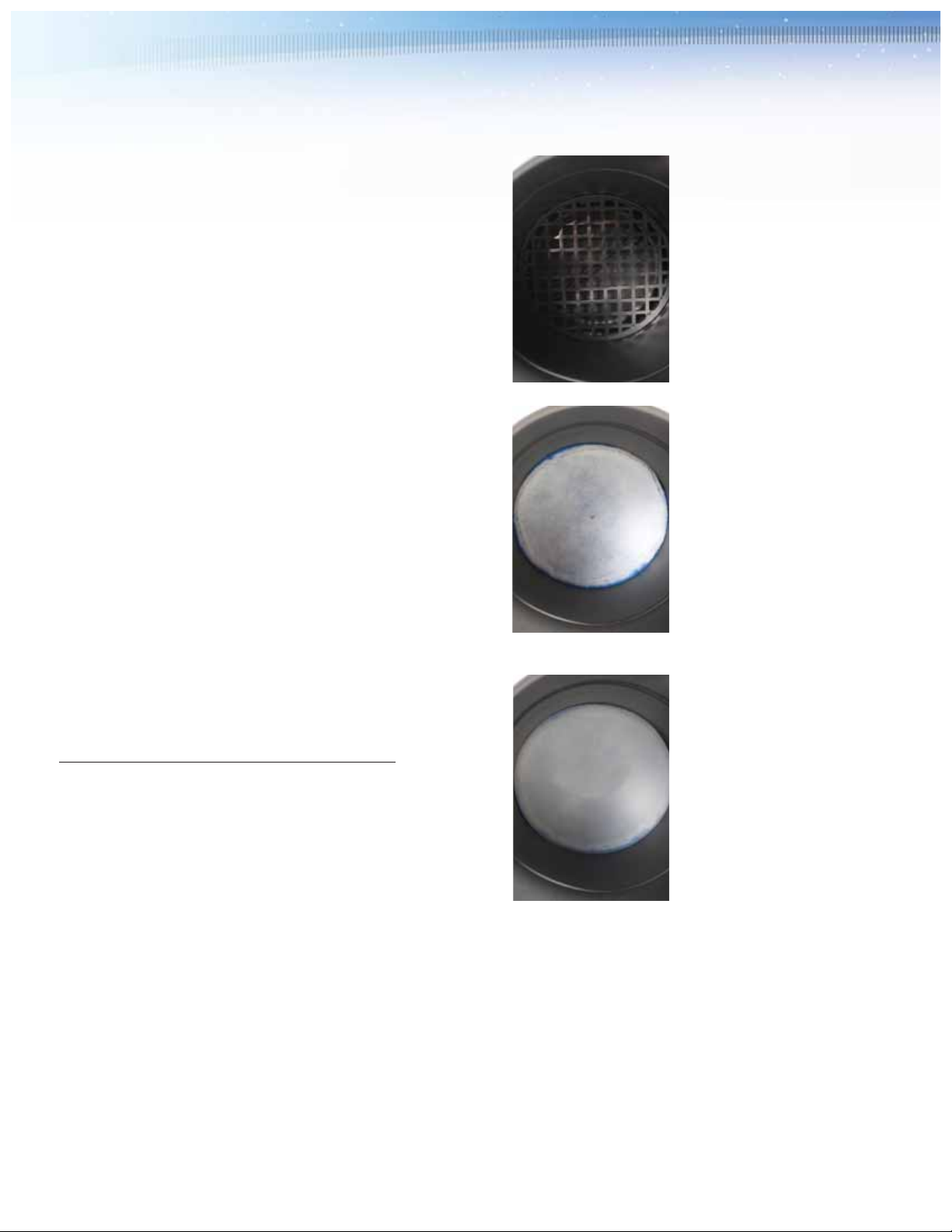
5.5 Cover Lid Sealing Gaskets
The proper maintenance of the cover lid sealing gaskets is critical to
the performance of the system. Check the gaskets carefully whenever
the gas phase chemical filters are replaced. If gaskets are worn,
frayed, or damaged in any way they should be replaced. Check the
seal between the lid and the tank whenever new SAAF chemical
media is installed.
5.6 General System Maintenance
Ducts, external PORTA-Scrubber surfaces, latches, blower, and
other system infrastructure should be checked at least every 6
months. Internal surfaces shall be examined whenever filters are
replaced. Examine all components for the following:
5.6.1 Cleanliness: Sweep and vacuum all standing dust or dirt in
the system. If using cleaning solvents, be mindful of the impact of
solvents on the performance and life of the chemical media and
take appropriate precautions to protect the system.
5.6.2 Water: The system should be completely dry at all times.
The presence of standing water, condensation, or dampness is
detrimental to the performance and life of the system. Determine
and remove the cause for the presence of water in the system, dry
the system, and examine all components for the presence of molds
and other biological growth. Remove all contamination, clean and
sterilize as necessary.
5.6.3 Filter System Integrity: Ensure that the unit contains the
appropriate filter elements, both particulate and gas phase, and
that these elements are correctly installed. Check for missing or
improperly installed components and review the system seals.
Check for air leaks at joints and seams and replace gaskets,
worn hardware, and seal with caulk as necessary.
5.6.4 Duct and System Integrity: Examine the entire system to
ensure that contaminated air cannot leak around the filter system.
Check all perimeter seals and repair as necessary.
5.6.5 Corrosion: If metal components are corroded repair the
corrosion and provide protective coatings as necessary. Be mindful
of the impact of painting on the performance and life of the
chemical media, and take appropriate precautions to protect the
system. Determine the source of the corrosion and rectify.
4.0 Start-Up Instructions
Immediately on start-up, examine the filter system for any apparent
air leaks or other anomalies. Air leaks may be detected by noise
or by use of a synthetic smoke puffing device at the external joints
and seams of the filter system installation. Correct or repair any
discrepancies, as necessary. Repeat this examination after
24 hours of operation and again after one week of operation.
5.0 Maintenance
5.1 PolyKlean Blue filter: A PolyKlean Blue pad has been included
as part of the system. Under normal conditions, the filter can be
expected to last for between 10 and 12 months before reaching
its final recommended capacity loading (see the AAF drawings
for details). However, this may vary under heavier or lighter
particulate loading conditions. At an air velocity of 75 feet per
minute the 2" deep PolyKlean Blue pad can be expected to have
an initial pressure drop in the range of less than 0.1" water gauge.
The recommended final pressure drop is 1.0 in. w.g.; however, it is
recommended that the PolyKlean Blue pad be replaced whenever
new chemical media is installed.
5.2 Chemical Media Monitoring
A discussion of sophisticated chemical media monitoring is beyond
the scope of this manual. At its most simple, when the system is
used to remove nuisance odors, the time to change out the chemical
media is when the odor begins to be regularly detected on the clean
side of the system. In more stringent applications, active real time
electronic and passive coupon corrosion monitoring systems are
available to determine the performance of the system. The remaining
life of the media can be determined by taking a sample of media and
returning it to AAF for analysis. Consult with your AAF representative
regarding active and passive monitoring systems and media sampling
for remaining life analysis.
5.3 Removal and Replacement of Particulate and Gas Phase
Chemical Media
Before removing activated carbon media, it is recommended the
media bed be grounded to release any electrostatic discharge.
Removal of filters will be the reverse of the installation process
described earlier in this manual. Filter and media replacement
will be carried out exactly the same as at initial installation detail with
use of manual or pneumatic methods. Reference appropriate safety
precautions related to specific gases being handled at the facility
and any operation instructions developed during the design phase
of the project.

11
6.0 Troubleshooting
Potential problems and causes listed are in no order of importance or priority. The causes are only
a list of the most common items to check to correct a problem. If you find the cause of a problem,
DO NOT assume it is the only cause of that problem. Different problems can have the same cause.
Problem Cause
Odors and Smells 1. Chemical media is spent.
2. Missing or damaged filters.
3. Incorrect media installed.
Airflow (CFM) Too Low 1. Blower wheel turning in wrong direction.
2. Actual system static pressure is higher than expected.
3. Motor speed (RPM) too low.
4. Dampers or valves not adjusted properly.
5. Leaks or obstructions in duct work.
6. Filters dirty.
7. Inlet and/or discharge guards are clogged.
8. Duct elbow too close to blower discharge.
9. Improperly designed duct work.
10. Condensation of moisture blinding the particulate and/or
chemical media.
11. Presence of moisture in the filters combined with freezing
temperatures can cause the filters to become impassible.
Airflow (CFM) Too High 1. Actual system static pressure is lower than expected.
2. Motor speed (RPM) too high.
3. Filters not in place.
4. Dampers or valves not adjusted properly.
Excessive Vibration 1. Loose mounting bolts, wheel set screws, taper-lock hubs.
2. Worn or corroded blower wheel.
3. Accumulation of foreign material on blower wheel.
4. Bent motor shaft.
5. Worn motor bearings.
6. Motor out of balance.
7. Inadequate structural support.
8. Support structure not sufficiently cross braced.
9. Weak or resonant foundation.
10. Foundation not flat and level.
Motor Overheating NOTE: A normal motor will operate at 174ºF.
1. Actual system static pressure is lower than expected.
2. Voltage supplied to motor is too high or too low.
3. Motor speed (RPM) too high or defective motor.
4. Air density higher than expected.
5. Motor wired correctly or loose wiring connections.
Excessive Noise 1. Wheel rubbing inside of housing.
2. Worn or corroded blower wheel.
3. Accumulation of foreign material on blower wheel.
4. Loose mounting bolts, wheel set screws, or taper-lock hubs.
5. Bent motor shaft.
6. Worn motor bearings.
7. Motor out of balance.
8. Motor bearings need lubrication.
9. System resonance or pulsation.
Fan Doesn’t Operate 1. Motor wired incorrectly or loose wiring connections.
2. Incorrect voltage supply.
3. Defective fuses or circuit breakers.
4. Power turned off elsewhere.
5. Defective motor.

SAAF™PORTA-Scrubber
AAF has a policy of continuous product research and
improvement and reserves the right to change
design and specifications without notice.
10300 Ormsby Park Place Suite 600
Louisville, Kentucky 40223-6169
www.aafintl.com
Customer Service 888.AAF.2003
Fax 888.223.6500
ISO Certified Firm
©2009 AAF International
The USGBC Member logo is a trademark owned by the
U.S. Green Building Council and is used by permission.
GPF-3-120 JUL '09 QG 100
7.0 Spare Parts List
It is recommended that the following spare parts be stored at the installation site for routine maintenance
purposes. The quantities required will depend on the size of the system. Consult with your AAF
representative to determine actual quantities required. Minimum recommended quantities are provided
in the table below.
8.0 Equipment Characteristics, Dimensions, Operating
Weights, and Shipping Weights
PORTA-Scrubber Shipping & Operating Weights*
Model Shipping Weight Operating Weight
PS-200 105 lbs (47 kg) 280 lbs (168 kg)
PS-200NP 55 lbs (25 kg) 230 lbs (105 kg)
PS-500 210 lbs (95 kg) 805 lbs (358 kg)
PS-500NP 175 lbs (79 kg) 770 lbs (336 kg)
* Based on using media with a density of 35 lb/ft3. Depending on selection,
media density may vary.
AAF Part Number Description Recommended Spares
Refer to the original customer SAAF chemical media One full replacement included
purchase order and the AAF in the system
submittal drawing
358-012-024 24" round PolyKlean Blue filter for One replacement included in the system
PORTA-Scrubber 200
358-012-037 37" round PolyKlean Blue filter for One replacement included in the system
PORTA-Scrubber 500
To order replacement parts call: 1-888-223-2003.
This manual suits for next models
3
Table of contents
Other AAF Water Filtration System manuals