logo
Brands
  1. Home
  2. •
  3. Brands
  4. •
  5. Elkay
  6. •
  7. Water Dispenser
  8. •
  9. Elkay LZ Series Installation manual

Elkay LZ Series Installation manual

Other manuals for LZ Series

12

This manual suits for next models

4

Other Elkay Water Dispenser manuals

Elkay EZS8WSVRL2K Instructions for use

Elkay

Elkay EZS8WSVRL2K Instructions for use

Elkay EMABFD B Series Instructions for use

Elkay

Elkay EMABFD B Series Instructions for use

Elkay VRCHDTL8 Installation manual

Elkay

Elkay VRCHDTL8 Installation manual

Elkay EZO Series Installation manual

Elkay

Elkay EZO Series Installation manual

Elkay EZ Series Installation manual

Elkay

Elkay EZ Series Installation manual

Elkay EZSTLG8L Installation manual

Elkay

Elkay EZSTLG8L Installation manual

Elkay LVRCDWS A Series Guide

Elkay

Elkay LVRCDWS A Series Guide

Elkay ERPB8C 3C Series Installation manual

Elkay

Elkay ERPB8C 3C Series Installation manual

Elkay VRC8FR 1C Series Installation manual

Elkay

Elkay VRC8FR 1C Series Installation manual

Elkay EZH2O LZS8WS 1A Series Installation manual

Elkay

Elkay EZH2O LZS8WS 1A Series Installation manual

Elkay EMABFTL Instructions for use

Elkay

Elkay EMABFTL Instructions for use

Elkay ESWA13 1F Series Installation manual

Elkay

Elkay ESWA13 1F Series Installation manual

Elkay EZO Series Guide

Elkay

Elkay EZO Series Guide

Elkay EZ Series Instructions for use

Elkay

Elkay EZ Series Instructions for use

Elkay VRCTLR8 1D Series Installation manual

Elkay

Elkay VRCTLR8 1D Series Installation manual

Elkay EZSG8WS 1B Series Instructions for use

Elkay

Elkay EZSG8WS 1B Series Instructions for use

Elkay EFA Series Installation manual

Elkay

Elkay EFA Series Installation manual

Elkay EZOOTL Series Guide

Elkay

Elkay EZOOTL Series Guide

Elkay EZH2O LVRC8WS Installation manual

Elkay

Elkay EZH2O LVRC8WS Installation manual

Elkay VRCHD8 Series Installation manual

Elkay

Elkay VRCHD8 Series Installation manual

Elkay LZO8TLx1C Installation manual

Elkay

Elkay LZO8TLx1C Installation manual

Elkay EZSTLDWS 1G Series Instructions for use

Elkay

Elkay EZSTLDWS 1G Series Instructions for use

Elkay EMABF8WS*1D Series Instructions for use

Elkay

Elkay EMABF8WS*1D Series Instructions for use

Elkay EZH2O VRCGNDWS C Series Installation manual

Elkay

Elkay EZH2O VRCGNDWS C Series Installation manual

Popular Water Dispenser manuals by other brands

Monarch Water ULTIMATE MINI AQUA HE install guide

Monarch Water

Monarch Water ULTIMATE MINI AQUA HE install guide

Haier HLM-109B instruction manual

Haier

Haier HLM-109B instruction manual

abc Fleck 5600SXT manual

abc

abc Fleck 5600SXT manual

GE GXOF18G Owner's manual and installation instructions

GE

GE GXOF18G Owner's manual and installation instructions

Kenmore 625.385560 UltraFilter 650 owner's manual

Kenmore

Kenmore 625.385560 UltraFilter 650 owner's manual

Innova CEV+ Installation, use and maintenance

Innova

Innova CEV+ Installation, use and maintenance

Aries Hydra DI Operation & maintenance manual

Aries

Aries Hydra DI Operation & maintenance manual

GE GNCF02H owner's manual

GE

GE GNCF02H owner's manual

ProFlo PFB Series Installation & operation manual

ProFlo

ProFlo PFB Series Installation & operation manual

A.O. Smith FREZYA 300S user manual

A.O. Smith

A.O. Smith FREZYA 300S user manual

Frakco Travelsoft RV 2400HD Operation instructions

Frakco

Frakco Travelsoft RV 2400HD Operation instructions

Avanti WD31EC instruction manual

Avanti

Avanti WD31EC instruction manual

Avanti WD360 instruction manual

Avanti

Avanti WD360 instruction manual

BRIO CLCTTL520 Setup manual

BRIO

BRIO CLCTTL520 Setup manual

3M HCD-1 operating instructions

3M

3M HCD-1 operating instructions

Coway CHP-671L manual

Coway

Coway CHP-671L manual

Aqua Essentials Borg & Overström B4 user guide

Aqua Essentials

Aqua Essentials Borg & Overström B4 user guide

KENT 11063 Instruction handbook

KENT

KENT 11063 Instruction handbook

https://manuals.online logo
https://manuals.online logoBrands
  • About & Mission
  • Contact us
  • Privacy Policy
  • Terms and Conditions

Copyright 2026 Manuals.Online. All Rights Reserved.

Page 1 1000002234 (Rev. A - 11/14)
EZFS8*2FQ, LZFS8*2FQ
Uses HFC-134A refrigerant
EZ™ & LZ ™ Series Barrier-Free Water Coolers
9
17,23
18
3
21
5
See Fig. 4 or 5
11
25
24
22
16
26
19
8
22
See Fig. 3
20
15
1
15
7
3
Fig. 1 4
2
3
INSTALLATION, CARE & USE MANUAL
Page 2
EZFS8*2FQ, LZFS8*2FQ
1000002234 (Rev. A - 11/14)
5 7/8"
150mm
12 1/2"
318mm
27"
686mm
31 11/32"
796mm
32 7/8"
835mm
19 1/32"
483mm
8 1/16"
205mm
13 15/16"
354mm
C
HANGER BRACKET
A
2"
51mm
3 7/8"
98mm
5 3/4"
146mm
7"
178mm 7"
178mm
F
C
L
17 7/16"
443mm
19"
483mm
21 7/8"
556mm
D
E
B
18 3/8"
467mm
ORIFICE
HEIGHT
RIM HEIGHT
3"
77mm
2"
51mm
28 13/16"
732mm
2"
51mm
E
6 3/8"
162mm 6 3/8"
162mm
9/32" OHOLES (6)
7mm
FINISHED FLOOR
ADA
REQUIREMENT
- REDUCE HEIGHT BY 3 INCHES FOR INSTALLATION OF CHILDRENS ADA COOLER.
*
*
*
*
*
*
*
*
*
*
LEGEND/LEYENDA/LÉGENDE
A = RECOMMENDED WATER SUPPLY LOCATION 3/8” O.D. UNPLATED COPPER TUBE CONNECT STUB WITH SHUT OFF (BY OTHERS) 3” (76mm) MAXIMUM OUT FROM WALL
La UBICACION 3/8” O RECOMENDADA de ABASTECIMIENTO DE AGUA. D. El TUBO del COBRE de UNPLATED CONECTA TALONARIO CON APAGO (POR OTROS) 3 en. (76 Mm) el MAXIMO FUERA DE PARED
L’O.D de 3/8” d’EMPLACEMENT DE PROVISION D’EAU RECOMMANDE. LE TUBE DE CUIVRE DE UNPLATED CONNECTE STUB AVEC ETEINT (PAR LES AUTRES) 3 dans. (76 mm) le MAXIMUM HORS DU MUR
B = RECOMMENDED LOCATION FOR WASTE OUTLET 1-1/4” O.D. DRAIN STUB 2” OUT FROM WALL
UBICACIÓN RECOMENDADA PARA EL DRENAJE DE SALIDA DE AGUA, DE 1¼” DE DIÁMETRO. El TALONARIO 2 FUERA DE PARED
EMPLACEMENT RECOMMANDÉ POUR LE DRAIN DE D.E. 1-1/4” DE SORTIE D’EAU. STUB 2 HORS DU MUR
C = 1-1/4” TRAP NOT FURNISHED
PURGADOR DE 1¼” NO PROPORCIONADO
SIPHON 1-1/4” NON FOURNI
D = ELECTRICAL SUPPLY (3) WIRE RECESSED BOX
CAJA RECESIVA DE ALAMBRES (3) DE SUMINISTRO ELÉCTRICO
BOÎTE ENCASTRÉE D’ALIMENTATION ÉLECTRIQUE (3) FILS
E = INSURE PROPER VENTILATION BY MAINTAINING 6” (152 mm) (MIN.) CLEARANCE FROM CABINET LOUVERS TO WALL.
ASEGURE UNA VENTILACIÓN ADECUADA MANTENIENDO UN ESPACIO E 6” (152 mm) (MÍN.) DE HOLGURA ENTRE LA REJILLA DE VENTILACIÓN DEL MUEBLE Y LA PARED
ASSUREZ-VOUS UNE BONNE VENTILATION EN GARDANT 6” (152 mm) (MIN.) ENTRE LES ÉVENTS DE L’ENCEINTE ET LE MUR.
F = 7/16” BOLT HOLES FOR FASTENING UNIT TO WALL
AGUJEROS DE LAS TUERCAS DE 7/16” PARA SUJETAR LA UNIDAD A LA PARED
TROUS D’ÉCROUS 7/16” POUR FIXER L’APPAREIL AU MUR
**NEW INSTALLATIONS MUST USE GROUND FAULT CIRCUIT INTERRUPTER (GFCI)
**Las nuevas instalaciones deben utilizar el interruptor de circuito de tierra de la avería (GFCI)
**Les nouvelles installations doivent employer l’interrupteur de circuit moulu de défaut (GFCI)
Fig. 2
Page 3 1000002234 (Rev. A - 11/14)
EZFS8*2FQ, LZFS8*2FQ
Lower and Upper Shroud
To access the refrigeration system and plumbing connections, remove four screws from bottom
of cooler to remove the lower shroud. To remove the upper shroud for access to the pushbars,
regulator, solenoid valve or other components located in the top of the unit, remove lower shroud,
disconnect drain, remove four screws from tabs along lower edge of upper shroud, unplug two wires
and water tube.
Switches Behind the Push Bar
The regulator, in an EZ cooler is always held fully open by the use of a single regulator nut (See Fig.
6). Water is not dispensed until the pushbar is depressed to activate a switch which then opens
a solenoid valve. When installing the regulator nut, the regulator spring must be depressed while
turning the nut.
Single bar units will have the same wiring as side push bar units but will not have the extra leads
attached to sidebars.
To remove sidebars, from the inside compress the ared tabs and pull out carefully. To reinstall side
pushbars, the front of the pushbar is inserted rst. While keeping the switch depressed, snap the
rear of the pushbar into position.
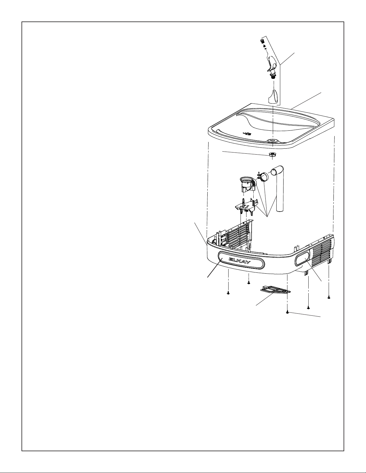
Service Instructions
12 - Bubbler
Assembly
Fig. 3
2
12
7
22
15
69
Bubbler
To remove the bubbler, rst disconnect the power supply. The underside of the bubbler can be
reached through the access panel (Item 7) on the underside of the upper shroud (Item 6). Remove
the access panel by removing the retaining screw. To remove the bubbler, loosen locknut from the
underside of the bubbler and remove the tubing from the quick connect tting per the Operation Of
Quick Connect Fittings section in the General Instructions. After servicing, replace the access panel
and retaining screw.
15
HANGER BRACKETS & TRAP
INSTALLATION
1) Remove hanger bracket fastened to back of cooler by
removing one (1) screw.
2) Mount the hanger bracket as shown in Figure 2.
NOTE: Hanger Bracket MUST be supported securely.
Add xture support carrier if wall will not provide
adequate support. Anchor hanger securely to wall
using all six (6) 1/4 in. dia. mounting holes.
IMPORTANT:
5-7/8 in. (150mm) dimension from wall to centerline
of trap must be maintained for proper t.
INSTALLATION OF COOLER
3) Hang the cooler on the hanger bracket. Be certain
the hanger bracket is engaged properly in the slots
on the cooler back as shown in Figure 2.
4) Remove the four (4) screws holding the lower front
panel at the bottom of cooler. Remove the front panel
by pulling straight down and set aside.
5) Connect water inlet line--See Note 4 of General
Instructions.
6) Install trap. Remove the slip nut and gasket from the
trap and install them on the cooler waste line making
sure that the end of the waste line ts into the trap.
Assemble the slip nut and gasket to the trap and
tighten securely.
IMPORTANT: If it is necessary to cut the drain, loosen
the screw at the black rubber boot and remove tube,
check for leaks after re-assembly.
7) Plug in electrical power. Unit must have
electrical power to have water ow.
START UP
Also See General Instructions
8) Stream height is factory set at 35 PSI. If supply pres-
sure varies greatly from this, adjust screw located on
the left side below push bar ass’y. on crossbar. CW
adjustment will raise stream and CCW adjustment will
lower stream. For best adjustment, stream should hit
basin approximately 6-1/2” (165mm) from bubbler on
the downward slope of the basin.
NOTE: If continuous ow occurs at the end of the com-
pressor cycle, turn cold control screw counterclock-
wise 1/4 turn.
9) Replace the front panel ensuring that the metal wrap-
per is secured inside of the upper shroud. Replace
all four screws previously removed.
Warm, soapy water or mild household cleaning products
can be used to clean the exterior panels of the EZ cool-
ers. Extra caution should be used to clean the mirror
nished stainless steel panels. They can be easily
scratched and should only be cleaned with mild soap and
water or Windex glass cleaner and a clean, soft cloth.
Use of harsh
chemicals or petroleum based or abrasive cleaners will
void the warranty.
CLEANING
Page 4
EZFS8*2FQ, LZFS8*2FQ
1000002234 (Rev. A - 11/14)
NOTE:
When installing replacement bubbler and pedestal, tighten
locknut only to hold parts snug in position. Do Not
Overtighten.
13
10
Cleaning the strainer
To clean the strainer, unscrew the cap of the
solenoid valve. Remove screen and rinse
thoroughly with water. Insert screen back
into solenoid valve and screw cap on. Make
sure the o-ring is placed properly.
11
Fig. 6
BUBBLER DETAIL VANDAL RESISTANT BUBBLER DETAIL
Basin
Fig. 5
12
Fig. 4
14
Locknut
Page 5 1000002234 (Rev. A - 11/14)
EZFS8*2FQ, LZFS8*2FQ
2
3
1
2
Fig. 7
WATERSENTRY®Filter Detail
DESCRIPTION
1
2
3
ITEM NO. PART NO.
51299C
98926C
51469C
Filter Assy-1500 Gal.
Kit-Filter Head Fitting includes
John Guest Fitting & 3/8”
Elbow Fitting
Assy -Filter & Bracket
includes Fltr Head/Mtg Bkt/
John Guest Ftgs/Screws
WATERSENTRY® FILTER PARTS LIST
(See Fig. 7)
Page 6
EZFS8*2FQ, LZFS8*2FQ
1000002234 (Rev. A - 11/14)
PRINTED IN U.S.A. FOR PARTS, CONTACT YOUR LOCAL DISTRIBUTOR OR CALL 1.800.834.4816
ELKAY MANUFACTURING COMPANY • 2222 CAMDEN COURT • OAK BROOK, IL 60523 • 630.574.8484
REPAIR SERVICE INFORMATION TOLL FREE NUMBER 1.800.260.6640
ITEM
NO.
28401C
55001109
36216C
1000002194
56092C
56229C
56213C
66703C
97970C
98169C
0000000802
92715C
40322C
98920C
98734C
98773C
36004C
0000000245
98776C
0000000256
98778C
98898C
36066C
75583C
98724C
1000002195
35826C
27413C
27416C
28030C
See Filter Table
Hanger Bracket
Basin - Stainless Steel
Wiring - Front/Side Push Bar
Compr - Service Pak
Tubing - Poly (Cut To Length)
Assy - Shroud Upper (Front Side Push)
Access Panel
Drier
Kit - Drain Replacement (EZ)(Brkt/Tube/Ftg/Clamp)
Kit - Replacement Cap/Screen/O-Ring
Kit - Solenoid Valve/Regulator Assy
Kit - Bubbler Assy
Orice Assy
Kit - Vandal Resistant Bubbler (VR)
Kit - Pushbar (Front/Side)
Kit - Cold Control/Screws
Wire - Jumper White
Kit - Fan Motor Assy/Blade/Mtr/Shroud/Screws/Nut
Kit - Condenser/Drier
Kit- Compr Mtg Hdwe/Grommets/Clips/Studs
Kit - Heatx/Drier
Kit - Hardware (EZ)
Power Cord
Elbow - 5/16” - 1/4”
Evaporator Assembly
Kit - Elect/Relay/Cover/Overload
Power Inlet
Wrapper - Light Grey
Wrapper - Stainless Steel
Brkt - Power Inlet
Water Filter Kit (When Provided)
PART NO. DESCRIPTION
1
2
3
*4
5
6
7
8
9
10
11
12
13
14
15
16
17
18
19
20
21
22
23
24
25
26
27
NS
NS
-
220V - 240V/50Hz PARTS LIST
*INCLUDES RELAY & OVERLOAD. IF UNDER
WARRANTY, REPLACE WITH SAME
COMPRESSOR USED IN ORIGINAL ASSEMBLY.
NOTE: All correspondence pertaining to any of the
above water coolers or orders for repair parts MUST
include Model No. and Serial No. of cooler, name and
part number of replacement part.
1
C
S
FAN
1
WHT
5
2
6
3
M
3
2
GND
SMOOTH
RIBBED
RELAY
OVERLOAD
COLD
CONTROL
SOLENOID
VALVE
SHORT WHITE LEAD
FROM POWER CORD
TO "L" TERMINAL ON
POWER INLET
TO "N" TERMINAL ON
POWER INLET
TO "GROUND" TERMINAL
ON POWER INLET
GREEN - GND
Fig. 10
220V-240V Wiring Diagram
GREEN LEAD
TO GROUND TERMINAL
ON POWER INLET
SMOOTH (BLACK) LEAD
TO "L" TERMINAL
ON POWER INLET
RIBBED (WHITE) LEAD
TO "N" TERMINAL
ON POWER INLET
27
Fig. 9