OBFATLFR8*1E OBFATLRFR8*1E
97786C (Rev. J - 4/05) PAGE4
Panel-Bottom Dispenser
Button - Push
Screw - Cap
Panel-RightSide
Panel-Left Side
Panel-FrontPush
Sleeve - Push Button
Cover - Cold Control
Washer
Screw-#8 x 5/8" Lg. Torx/Slot
Screw - Torx
Hex Nut
Panel - Screen
RetainingNut
Regulator
Holder-Regulator
Screw-#10 x 1/2" Lg. THSM
Cover-Dispenser Bottom
Power Cord (Pressure Unit)
Fan Blade
Hex Nut - Fan Blade
Fan Motor 115V
Screw - (Fan Motor)
Shroud - Fan
Screw - #8-18 x 3/8” Lg.
Heater Thermostat Assy
Strainer
Bubbler Assembly
Screw - Torx
Condenser
Drier
Panel - Front Lower
Panel - Right Rear (Left Unit)
Panel - Left Rear (Left Unit)
Panel - Right Rear (Right Unit)
Panel - Left Rear (Right Unit)
Stud - Compressor Mtg.
Grommet - Compressor Mtg.
Clip - Compressor Mtg.
CompressorServ. Pak EMI70 HNR
Relay
Cover - Relay
Heat Exchanger
Drain Tube (Left Unit)
Drain Tube (Right Unit)
Gasket - Drain
Ring Support - Drain
Clamp - Drain Gasket
Basin - Stainless Steel
Adaptor - Basin
Hex Nut #10-32
ColdControl
Evaporator Assembly
Screw - #10 x 1/2" Lg. HHSM
Overload
Tee - 1/4 x 1/4 x 1/4
Drain Tube Assembly
DrainTrimStrip
Tubing - Poly (Cut To Length)
Bubbler - Nipple
Power Cord (Non-pressure Unit)
Heater Strip
Rocker Switch
Gasket
Hanger Bracket (Not Shown)
22897C
45662C
75672C
22822C
22814C
27295C
45663C
27124C
56033C
70864C
75661C
40045C
27469C
15005C
61313C
50986C
75532C
55931C
35900C
30664C
70018C
31490C
70009C
22899C
38417001
35909C
55996C
98118C
75566C
62152C
66202C
22955C
26776C
22854C
22862C
26800C
101516143550
100806740570
19037000
36094C
35959C
35768C
66576C
45332C
45331C
50400C
50401C
70444C
21903C
27306C
70016C
31513C
66534C
111411443890
36158C
70682C
45449C
26847C
56092C
15009C
36012C
35906C
35907C
100322740560
400660943730
1
2
3
4
5
6
7
8
9
10
11
12
13
14
15
16
17
18
19
20
21
22
23
24
25
26
27
28
29
30
31
32
33
34
35
36
37
38
39
*40
41
42
43
44
45
46
47
48
49
50
51
52
53
54
55
56
57
58
59
60
61
62
63
64
NS
ITEMNO. PARTNO. DESCRIPTION
*REPLACE WITH SAME COMPRESSOR USED IN ORIGINALASSEMBLY.
NOTE: All correspondence pertaining to any of the above water coolers or orders
for repair parts MUST include Model No. and Serial No. of cooler, name and part
number of replacement part
WARNING!
This unit is frost resistant down to 0° F with no wind. Prevail-
ing winds can reduce the ability of the heater element to
preventlight freezing. Iftheambient air temperaturewilldrop
below 0° F, the cooler needs to be drained of all water by
blowingout all water lines, evaporator (item53),and the
drain trap.Aheater strip is used to heat the unit and will
begin to cycle at 40° +/- 5° F. A check at this temperature
will ensure the heater is working and the unit is resistant to
lightfreezing.
ALSO,MAKE SURE THERE ARE NOPLASTIC OR
FLAMMABLECOMPONENTSDIRECTLYABOVETHE
HEATER STRIP.
ELKAYMANUFACTURING COMPANY • 2222 CAMDEN COURT • OAK BROOK, IL60523 • 630.574.8484
PRINTEDINU.S.A. FOR PARTS, CONTACT YOUR LOCAL DISTRIBUTOR OR CALL 1.800.323.0620
29
29
13
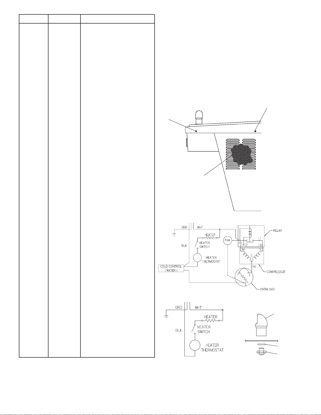
FIG. 4
FIG. 5
(with Compressor)
FIG. 6
(without Compressor)
28
60
64
FIG. 7
REPAIR SERVICE INFORMATION TOLL FREE NUMBER 1-800-260-6640